Smooth engine operation, without jerks or power surges, is the key to its durability. To control these indicators, an electric motor speed controller is used for 220V, 12V and 24V; all of these frequencies can be made with your own hands or you can buy a ready-made unit.
Why do you need a speed controller?
An engine speed controller, a frequency converter, is a device with a powerful transistor, which is necessary to invert the voltage, as well as to ensure smooth stopping and starting of an asynchronous motor using PWM. PWM – wide-pulse control of electrical devices. It is used to create a specific sinusoid of alternating and direct current.
Photo - a powerful regulator for an asynchronous motorThe simplest example of a converter is a conventional voltage stabilizer. But the device under discussion has a much wider range of operation and power.
Frequency converters are used in any device that is powered by electrical energy. Governors provide extremely precise electrical motor control so that engine speed can be adjusted up or down, maintaining revs at the desired level, and protecting instruments from sudden revving. In this case, the electric motor uses only the energy needed to operate, instead of running it at full power.
 Photo – DC motor speed controller
 Why do you need a speed controller for an asynchronous electric motor:
- To save energy. By controlling the speed of the motor, the smoothness of its start and stop, strength and speed, you can achieve significant savings in personal funds. As an example, reducing speed by 20% can result in energy savings of 50%.
- The frequency converter can be used to control process temperature, pressure or without the use of a separate controller;
- No additional controller required for soft start;
- Maintenance costs are significantly reduced.
The device is often used for a welding machine (mainly for semi-automatic machines), an electric stove, a number of household appliances (vacuum cleaner, sewing machine, radio, washing machine), home heater, various ship models, etc.
Operating principle of the speed controller
The speed controller is a device consisting of the following three main subsystems:
- AC motor;
- Main drive controller;
- Drive and additional parts.
When the AC motor is started at full power, current is transferred with the full power of the load, this is repeated 7-8 times. This current bends the motor windings and generates heat that will be generated for a long time. This can significantly reduce engine longevity. In other words, the converter is a kind of step inverter that provides double energy conversion.
 Photo - diagram of the regulator for a commutator motor
 Depending on the incoming voltage, the frequency regulator of the speed of a three-phase or single-phase electric motor rectifies the current of 220 or 380 volts. This action is carried out using a rectifying diode, which is located at the energy input. Next, the current is filtered using capacitors. Next, PWM is generated, the electrical circuit is responsible for this. Now the windings of the induction motor are ready to transmit the pulse signal and integrate them into the desired sine wave. Even with a microelectric motor, these signals are issued, literally, in batches.
 Photo - sinusoid of normal operation of an electric motor
 How to choose a regulator
There are several characteristics by which you need to choose a speed controller for a car, machine electric motor, or household needs:
- Control type. For commutator motors, there are regulators with a vector or scalar control system. The former are more often used, but the latter are considered more reliable;
- Power. This is one of the most important factors for choosing an electrical frequency converter. It is necessary to select a frequency generator with a power that corresponds to the maximum permissible on the protected device. But for a low-voltage motor it is better to choose a regulator more powerful than the permissible watt value;
- Voltage. Naturally, everything here is individual, but if possible, you need to buy a speed controller for an electric motor, the circuit diagram of which has a wide range of permissible voltages;
- Frequency range. Frequency conversion is the main task of this device, so try to choose a model that will best suit your needs. Let's say, for a manual router, 1000 Hertz will be enough;
- According to other characteristics. This is the warranty period, the number of inputs, the size (there is a special attachment for desktop machines and hand tools).
At the same time, you also need to understand that there is a so-called universal rotation regulator. This is a frequency converter for brushless motors.
 Photo – regulator diagram for brushless motors
 There are two parts in this circuit - one is logical, where the microcontroller is located on the chip, and the second is power. Basically, such an electrical circuit is used for a powerful electric motor.
Video: electric motor speed controller with SHIRO V2
How to make a homemade engine speed controller
You can make a simple triac motor speed controller, its diagram is presented below, and the price consists only of parts sold in any electrical store.
To work, we need a powerful triac of the BT138-600 type, it is recommended by a radio engineering magazine.
 Photo - do-it-yourself speed controller diagram
 In the described circuit, the speed will be adjusted using potentiometer P1. Parameter P1 determines the phase of the incoming pulse signal, which in turn opens the triac. This scheme can be used both in field farming and at home. You can use this regulator for sewing machines, fans, tabletop drilling machines.
The principle of operation is simple: at the moment when the motor slows down a little, its inductance drops, and this increases the voltage in R2-P1 and C3, which in turn leads to a longer opening of the triac.
A thyristor feedback regulator works a little differently. It allows energy to flow back into the energy system, which is very economical and beneficial. This electronic device involves the inclusion of a powerful thyristor in the electrical circuit. His diagram looks like this:

Here, to supply direct current and rectify, a control signal generator, an amplifier, a thyristor, and a speed stabilization circuit are required.
Not every modern drill or grinder is equipped with a factory speed regulator, and most often speed control is not provided at all. However, both grinders and drills are built on the basis of commutator motors, which allows each of their owners, even if they know how to handle a soldering iron, to make their own speed controller from available electronic components, either domestic or imported.
In this article we will look at the diagram and principle of operation of the simplest engine speed controller for a power tool, and the only condition is that the engine must be a commutator type - with characteristic lamellas on the rotor and brushes (which sometimes spark).
The above diagram contains a minimum of parts and is suitable for power tools up to 1.8 kW and above, for a drill or grinder. A similar circuit is used to regulate speed in automatic washing machines that have commutator high-speed motors, as well as in dimmers for incandescent lamps. Such circuits, in principle, will allow you to regulate the heating temperature of a soldering iron tip, an electric heater based on heating elements, etc.
The following electronic components will be required:
Constant resistor R1 - 6.8 kOhm, 5 W.
Variable resistor R2 - 2.2 kOhm, 2 W.
Constant resistor R3 - 51 Ohm, 0.125 W.
Film capacitor C1 - 2 µF 400 V.
Film capacitor C2 - 0.047 uF 400 volts.
Diodes VD1 and VD2 - for voltage up to 400 V, for current up to 1 A.
Thyristor VT1 - for the required current, for a reverse voltage of at least 400 volts.
The circuit is based on a thyristor. A thyristor is a semiconductor element with three terminals: anode, cathode, and control electrode. After a short pulse of positive polarity is applied to the control electrode of the thyristor, the thyristor turns into a diode and begins to conduct current until this current in its circuit is interrupted or changes direction.
After the current stops or when its direction changes, the thyristor will close and stop conducting current until the next short pulse is applied to the control electrode. Well, since the voltage in the household network is alternating sinusoidal, then each period of the network sinusoid the thyristor (as part of this circuit) will work strictly starting from the set moment (in the set phase), and the less the thyristor is open during each period, the lower the speed will be power tool, and the longer the thyristor is open, the higher the speed will be.
As you can see, the principle is simple. But when applied to a power tool with a commutator motor, the circuit works more cleverly, and we will talk about this later.
So, the network here includes in parallel: a measuring control circuit and a power circuit. The measuring circuit consists of constant and variable resistors R1 and R2, capacitor C1, and diode VD1. What is this chain for? This is a voltage divider. The voltage from the divider, and what is important, the back-EMF from the motor rotor, add up in antiphase, and form a pulse to open the thyristor. When the load is constant, then the open time of the thyristor is constant, therefore the speed is stabilized and constant.
As soon as the load on the tool, and therefore on the engine, increases, the value of the back-EMF decreases, since the speed decreases, which means the signal to the control electrode of the thyristor increases, and opening occurs with less delay, that is, the power supplied to the engine increases, increasing the dropped speed . This way the speed remains constant even under load.

As a result of the combined action of signals from the back-EMF and from the resistive divider, the load does not greatly affect the speed, but without a regulator this influence would be significant. Thus, using this circuit, stable speed control is achievable in each positive half-cycle of the network sinusoid. At medium and low rotation speeds this effect is more pronounced.
However, with increasing speed, that is, with increasing voltage removed from the variable resistor R2, the stability of maintaining a constant speed decreases.
In this case, it is better to provide a shunt button SA1 parallel to the thyristor. The function of diodes VD1 and VD2 is to ensure half-wave operation of the regulator, since the voltages from the divider and the rotor are compared only in the absence of current through the motor.
Capacitor C1 expands the control zone at low speeds, and capacitor C2 reduces sensitivity to interference from brush sparking. The thyristor needs to be highly sensitive so that a current of less than 100 μA can open it.
Another review on the topic of all sorts of things for homemade products. This time I will talk about the digital speed controller. The thing is interesting in its own way, but I wanted more.
For those interested, read on :)
Having on the farm some low-voltage devices such as a small grinder, etc. I wanted to increase their functional and aesthetic appearance a little. True, it didn’t work out, although I still hope to achieve my goal, perhaps another time, but I’ll tell you about the little thing itself today.
The manufacturer of this regulator is Maitech, or rather this name is often found on all sorts of scarves and blocks for homemade products, although for some reason I did not come across the website of this company.
Due to the fact that I didn’t end up doing what I wanted, the review will be shorter than usual, but I’ll start, as always, with how it is sold and sent.
The envelope contained a regular zip-lock bag. 
The kit includes only a regulator with a variable resistor and a button, there is no hard packaging or instructions, but everything arrived intact and without damage. 
There is a sticker on the back that replaces the instructions. In principle, nothing more is required for such a device.
The operating voltage range is 6-30 Volts and the maximum current is 8 Amps. 
The appearance is quite good, dark “glass”, dark gray plastic of the case, when turned off it seems completely black. In appearance, it's a good one, there's nothing to complain about. Shipping film was glued to the front.
Installation dimensions of the device:
Length 72mm (minimum hole in case 75mm), width 40mm, depth excluding front panel 23mm (with front panel 24mm).
Front panel dimensions:
Length 42.5, mm width 80mm 
A variable resistor is included with the handle; the handle is certainly rough, but it’s fine for use.
The resistor resistance is 100KOhm, the adjustment dependence is linear.
As it turned out later, 100KOhm resistance gives a glitch. When powered from a switching power supply, it is impossible to set stable readings, the interference on the wires to the variable resistor affects, which is why the readings jump +\- 2 digits, but it would be fine if they jumped, and at the same time the engine speed jumps.
The resistance of the resistor is high, the current is small and the wires collect all the noise around.
When powered from a linear power supply, this problem is completely absent.
The length of the wires to the resistor and button is about 180mm. 
Button, well, nothing special here. Contacts are normally open, installation diameter 16mm, length 24mm, no backlight.
The button turns off the engine.
Those. When power is applied, the indicator turns on, the engine starts, pressing the button turns it off, a second press turns it on again.
When the engine is turned off, the indicator also does not light up. 
Under the cover there is a device board.
The terminals contain power supply and motor connection contacts.
The positive contacts of the connector are connected together, the power switch switches the negative wire of the engine.
The connection of the variable resistor and the button is detachable.
Everything looks neat. The capacitor leads are a little crooked, but I think that can be forgiven :) 
I will hide further disassembly under a spoiler.
More details
The indicator is quite large, the height of the digit is 14mm.
Board dimensions 69x37mm. 
The board is assembled neatly, there are traces of flux near the indicator contacts, but overall the board is clean.
The board contains: a diode for protection against polarity reversal, a 5 Volt stabilizer, a microcontroller, a 470 uF 35 Volt capacitor, power elements under a small radiator.
Places for installing additional connectors are also visible, their purpose is unclear. 
I sketched out a small block diagram, just for a rough understanding of what is switched and how it is connected. The variable resistor is connected with one leg to 5 Volts, the other to the ground. therefore, it can be easily replaced with a lower denomination. The diagram does not show connections to an unsoldered connector. 
The device uses a microcontroller manufactured by STMicroelectronics.
As far as I know, this microcontroller is used in quite a lot of different devices, such as ampere-voltmeters. 
The power stabilizer heats up when operating at maximum input voltage, but not very much. 
Part of the heat from the power elements is transferred to the copper polygons of the board; on the left you can see a large number of transitions from one side of the board to the other, which helps remove heat.
Heat is also removed using a small radiator, which is pressed to the power elements from above. This placement of the radiator seems somewhat questionable to me, since heat is dissipated through the plastic of the case and such a radiator does not help much.
There is no paste between the power elements and the radiator, I recommend removing the radiator and coating it with paste, at least a little bit will improve. 
A transistor is used in the power section, the channel resistance is 3.3 mOhm, the maximum current is 161 Amps, but the maximum voltage is only 30 Volts, so I would recommend limiting the input at 25-27 Volts. When operating at near-maximum currents, there is slight heating.
There is also a diode nearby that dampens current surges from the motor’s self-induction.
10 Amperes, 45 Volts are used here. There are no questions about the diode. 
First start. It so happened that I carried out the tests even before removing the protective film, which is why it is still there in these photos.
The indicator is contrasty, moderately bright, and perfectly readable. 
At first I decided to try it on small loads and received the first disappointment.
No, I have no complaints against the manufacturer or the store, I just hoped that such a relatively expensive device would have stabilization of engine speed.
Alas, this is just an adjustable PWM, the indicator displays % fill from 0 to 100%.
The regulator didn’t even notice the small motor, it’s a completely ridiculous load current :) 
Attentive readers probably noticed the cross-section of the wires with which I connected the power to the regulator.
Yes, then I decided to approach the issue more globally and connected a more powerful engine.
It is, of course, noticeably more powerful than the regulator, but at idle its current is about 5 Amps, which made it possible to test the regulator in modes closer to maximum.
The regulator behaved perfectly, by the way, I forgot to point out that when turned on, the regulator smoothly increases the PWM filling from zero to the set value, ensuring smooth acceleration, while the indicator immediately shows the set value, and not like on frequency drives, where the real current one is displayed.
The regulator did not fail, it warmed up a little, but not critically. 
Since the regulator is pulse, I decided, just for fun, to poke around with an oscilloscope and see what happens at the gate of the power transistor in different modes.
The PWM operating frequency is about 15 KHz and does not change during operation. The engine starts at approximately 10% fill. 

Initially, I planned to install a regulator in my old (most likely ancient) power supply for a small power tool (more on that another time). In theory, it should have been installed instead of the front panel, and the speed controller should have been located on the back; I didn’t plan to install a button (fortunately, when turned on, the device immediately goes into on mode).
It had to turn out beautiful and neat. 
But then some disappointment awaited me.
1. Although the indicator was slightly smaller in size than the front panel insert, the worse thing was that it did not fit in depth, resting against the racks for connecting the halves of the case.
and even if the plastic of the indicator housing could have been cut off, I wouldn’t have done it anyway, since the regulator board was in the way.
2. But even if I had solved the first question, there was a second problem: I completely forgot how my power supply was made. The fact is that the regulator breaks the minus power supply, and further along the circuit I have a relay for reverse, turning on and forcing the engine to stop, and a control circuit for all this. And remaking them turned out to be much more complicated :(
If the regulator were with speed stabilization, then I would still get confused and redo the control and reverse circuit, or remake the regulator for + power switching. Otherwise, I can and will redo it, but without enthusiasm and now I don’t know when.
Maybe someone is interested, a photo of the insides of my power supply, it was assembled like this about 13-15 years ago, it worked almost all the time without problems, once I had to replace the relay. 
Summary.
pros
The device is fully operational.
Neat appearance.
High quality build
The kit includes everything you need.
Minuses.
Incorrect operation from switching power supplies.
Power transistor without voltage reserve
With such modest functionality, the price is too high (but everything is relative here).
My opinion. If you close your eyes to the price of the device, then in itself it is quite good, it looks neat and works fine. Yes, there is a problem of not very good noise immunity, I think it’s not difficult to solve, but it’s a little frustrating. In addition, I recommend not to exceed the input voltage above 25-27 Volts.
What’s more frustrating is that I’ve looked quite a lot at options for all sorts of ready-made regulators, but nowhere do they offer a solution with speed stabilization. Perhaps someone will ask why I need this. I’ll explain how I came across a grinding machine with stabilization; it’s much more pleasant to work with than a regular one.
That's all, I hope it was interesting :)
The product was provided for writing a review by the store. The review was published in accordance with clause 18 of the Site Rules.
I'm planning to buy +23 Add to favorites I liked the review +38 +64A high-quality and reliable rotation speed controller for single-phase commutator electric motors can be made using common parts in literally 1 evening. This circuit has a built-in overload detection module, provides a soft start of the controlled motor and a motor rotation speed stabilizer. This unit operates with voltages of both 220 and 110 volts.
Regulator technical parameters
- Supply voltage: 230 volts AC
- regulation range: 5…99%
- load voltage: 230 V / 12 A (2.5 kW with radiator)
- maximum power without radiator 300 W
- low noise level
- speed stabilization
- soft start
- board dimensions: 50×60 mm
Schematic diagram
 Scheme of motor regulator on a triac and U2008
 The control system module circuit is based on a PWM pulse generator and a motor control triac - a classic circuit design for such devices. Elements D1 and R1 ensure that the supply voltage is limited to a value that is safe for powering the generator microcircuit. Capacitor C1 is responsible for filtering the supply voltage. Elements R3, R5 and P1 are a voltage divider with the ability to regulate it, which is used to set the amount of power supplied to the load. Thanks to the use of resistor R2, which is directly included in the input circuit to the m/s phase, the internal units are synchronized with the VT139 triac.
 Printed circuit board
 The following figure shows the arrangement of elements on a printed circuit board. During installation and startup, attention should be paid to ensuring safe operating conditions - the regulator is powered by a 220V network and its elements are directly connected to the phase.
Increasing regulator power
In the test version, a BT138/800 triac with a maximum current of 12 A was used, which makes it possible to control a load of more than 2 kW. If you need to control even larger load currents, we recommend installing the thyristor outside the board on a large heatsink. You should also remember to select the correct FUSE fuse depending on the load.

In addition to controlling the speed of electric motors, you can use the circuit to adjust the brightness of lamps without any modifications.
When using an electric motor in tools, one of the serious problems is adjusting the speed of their rotation. If the speed is not high enough, then the tool is not effective enough.
If it is too high, then this leads not only to a significant waste of electrical energy, but also to possible burnout of the tool. If the rotation speed is too high, the operation of the tool may also become less predictable. How to fix it? For this purpose, it is customary to use a special rotation speed controller.
The motor for power tools and household appliances is usually one of 2 main types:
- Commutator motors.
- Asynchronous motors.
In the past, the second of these categories was most widespread. Nowadays, approximately 85% of motors used in electric tools, household or kitchen appliances are of the commutator type. This is explained by the fact that they are more compact, they are more powerful and the process of managing them is simpler.
The operation of any electric motor is based on a very simple principle: If you place a rectangular frame between the poles of a magnet, which can rotate around its axis, and pass a direct current through it, the frame will begin to rotate. The direction of rotation is determined according to the “right hand rule”.
This pattern can be used to operate a commutator motor.
The important point here is to connect the current to this frame. Since it rotates, special sliding contacts are used for this. After the frame rotates 180 degrees, the current through these contacts will flow in the opposite direction. Thus, the direction of rotation will remain the same. At the same time, smooth rotation will not work. To achieve this effect, it is customary to use several dozen frames.
Device

A commutator motor usually consists of a rotor (armature), stator, brushes and tachogenerator:
- Rotor- this is the rotating part, the stator is an external magnet.
- Brushes made of graphite- this is the main part of the sliding contacts, through which voltage is supplied to the rotating armature.
- Tachogenerator is a device that monitors rotation characteristics. In the event of a violation of the uniformity of movement, it adjusts the voltage supplied to the engine, thereby making it smoother.
- Stator may contain not one magnet, but, for example, 2 (2 pairs of poles). Also, instead of static magnets, electromagnet coils can be used here. Such a motor can operate on both direct and alternating current.
The ease of adjusting the speed of a commutator motor is determined by the fact that the rotation speed directly depends on the magnitude of the applied voltage.
In addition, an important feature is that the rotation axis can be directly attached to a rotating tool without the use of intermediate mechanisms.
If we talk about their classification, we can talk about:
- Brushed motors direct current.
- Brushed motors alternating current.
In this case, we are talking about what kind of current is used to power the electric motors.
Classification can also be made according to the principle of motor excitation. In a brushed motor design, electrical power is supplied to both the rotor and stator of the motor (if it uses electromagnets).
The difference lies in how these connections are organized.
Here it is customary to distinguish:
- Parallel excitation.
- Consistent excitation.
- Parallel-sequential excitation.
Adjustment

Let's list a few of these options as examples:
- Laboratory autotransformer(LATR).
- Factory adjustment boards, used in household appliances (you can use in particular those used in mixers or vacuum cleaners).
- Buttons, used in the design of power tools.
- Household regulators lighting with smooth action.
However, all of the above methods have a very important flaw. Along with the decrease in speed, the engine power also decreases. In some cases, it can be stopped even just with your hand. In some cases, this may be acceptable, but in most cases, it is a serious obstacle.
A good option is to adjust the speed using a tachogenerator. It is usually installed at the factory. If there are deviations in the motor rotation speed, an already adjusted power supply corresponding to the required rotation speed is transmitted to the motor. If you integrate motor rotation control into this circuit, then there will be no loss of power.
How does this look constructively? The most common are rheostatic rotation control, and those made using semiconductors.
In the first case, we are talking about variable resistance with mechanical adjustment. It is connected in series to the commutator motor. The disadvantage is the additional heat generation and additional waste of battery life. With this adjustment method, there is a loss of engine rotation power. Is a cheap solution. Not applicable for sufficiently powerful motors for the reasons mentioned.
In the second case, when using semiconductors, the motor is controlled by applying certain pulses. The circuit can change the duration of such pulses, which in turn changes the rotation speed without loss of power.
How to make it yourself?
There are various options for adjustment schemes. Let us present one of them in more detail.
Here is how it works:

Initially, this device was developed to adjust the commutator motor in electric vehicles. We were talking about one where the supply voltage is 24 V, but this design is also applicable to other engines.
The weak point of the circuit, which was identified during testing of its operation, is its poor suitability at very high current values. This is due to some slowdown in the operation of the transistor elements of the circuit.
It is recommended that the current be no more than 70 A. There is no current or temperature protection in this circuit, so it is recommended to build in an ammeter and monitor the current visually. The switching frequency will be 5 kHz, it is determined by capacitor C2 with a capacity of 20 nf.
As the current changes, this frequency can change between 3 kHz and 5 kHz. Variable resistor R2 is used to regulate the current. When using an electric motor at home, it is recommended to use a standard type regulator.
At the same time, it is recommended to select the value of R1 in such a way as to correctly configure the operation of the regulator. From the output of the microcircuit, the control pulse goes to a push-pull amplifier using transistors KT815 and KT816, and then goes to the transistors.
The printed circuit board has a size of 50 by 50 mm and is made of single-sided fiberglass:

This diagram additionally shows 2 45 ohm resistors. This is done for the possible connection of a regular computer fan to cool the device. When using an electric motor as a load, it is necessary to block the circuit with a blocking (damper) diode, which in its characteristics corresponds to twice the load current and twice the supply voltage.
Operating the device in the absence of such a diode may lead to failure due to possible overheating. In this case, the diode will need to be placed on the heat sink. To do this, you can use a metal plate that has an area of 30 cm2.
Regulating switches work in such a way that the power losses on them are quite small. IN In the original design, a standard computer fan was used. To connect it, a limiting resistance of 100 Ohms and a supply voltage of 24 V were used.
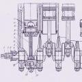
The assembled device looks like this:


When manufacturing a power unit (in the lower figure), the wires must be connected in such a way that there is a minimum of bending of those conductors through which large currents pass. We see that the manufacture of such a device requires certain professional knowledge and skills. Perhaps in some cases it makes sense to use a purchased device.
Selection criteria and cost
In order to correctly choose the most suitable type of regulator, you need to have a good idea of what types of such devices there are:
- Various types of control. Can be a vector or scalar control system. The former are used more often, while the latter are considered more reliable.
- Regulator power must correspond to the maximum possible engine power.
- By voltage It is convenient to choose a device that has the most universal properties.
- Frequency characteristics. The regulator that suits you should match the highest frequency that the motor uses.
- Other characteristics. Here we are talking about the length of the warranty period, dimensions and other characteristics.
Depending on the purpose and consumer properties, prices for regulators can vary significantly.
For the most part, they range from approximately 3.5 thousand rubles to 9 thousand:
- Speed controller KA-18 ESC, designed for 1:10 scale models. Costs 6890 rubles.
- MEGA speed controller collector (moisture-proof). Costs 3605 rubles.
- Speed controller for LaTrax 1:18 models. Its price is 5690 rubles.