Without a doubt, many novice radio amateurs will be interested in the design of a simple metal detector, the basis for which was a diagram that was repeatedly published in domestic and foreign specialized publications in the mid-70s of the last century. Using this metal detector, made with only two transistors, you can detect metal objects located several tens of centimeters away from the search coil.
Schematic diagram
This design is one of the variants of metal detectors of the FM (Frequency Meter) type, that is, it is a device based on the principle of measuring the frequency deviation of a reference oscillator under the influence of metal objects that fall within the range of the search coil. In this case, the frequency change is assessed by ear (Fig. 2.4).

Rice. 2.4. Schematic diagram of a simple metal detector using two transistors
The basis of the device circuit is a high-frequency generator and a receiver, which records changes in the frequency of the generator when approaching metal objects.
The high-frequency generator is assembled on transistor T1 according to a capacitive three-point circuit. The oscillatory circuit of the reference oscillator consists of a chain of series-connected capacitors C1, C2 and C3, to which coil L1 is connected. The operating frequency of the RF generator is determined by the inductance of this coil, which is also a search coil.
One of the features of this device is that it uses a heterodyne-type receiver as an analyzer, which is made with just one transistor. In this case, the cascade on transistor T2 combines the functions of a local oscillator and a detector. The heterodyne is assembled according to a three-point capacitive circuit. The advantage of this scheme is the possibility of using an inductor without taps, which, although slightly, simplifies the design. The local oscillatory circuit contains an inductor L2 and a capacitance made up of series-connected capacitors C4, C5 and C6. The local oscillator frequency can be changed by rotating the tuning core of coil L2.
From the collector of transistor T2, the detected signal is supplied to headphones BF1.
If there is a metal object near coil L1, its inductance will change. This will lead to a change in the frequency of the reference oscillator, which will be immediately registered by the metal detector receiver. As a result, the signal tone in BF1 phones will change.
Details and design
All parts of a simple metal detector with two transistors, with the exception of the search coil L1, local oscillator coil L2, connector X1 and switch S1, are located on a printed circuit board measuring 70x40 mm (Fig. 2.5), made of single-sided foil getinax or textolite.
There are no special requirements for the parts used in this device. It is advisable to use any small-sized capacitors and resistors that can be placed on a printed circuit board without any problems. As can be seen from the circuit diagram, this metal detector uses outdated RF transistors such as P422, P401 or P402. Instead, you can use any modern pnp RF transistors designed for operation in the input stages of radio receivers.
The L1 search coil used in the reference generator is a rectangular frame with dimensions of 175x230 mm, on which 32 turns of PEV-2 wire with a diameter of 0.35 mm or, for example, PELSHO with a diameter of 0.37 mm are wound.
Two cylindrical paper frames contain pieces of ferrite rod type 400NN or 600NN with a diameter of 7 mm. The length of the first of them, permanently fixed, is about 20-22 mm. The second rod is movable and is used to adjust the inductance of the coil. Its length is 35-40 mm. The frames of the rods are wrapped in paper tape, onto which 55 turns of PELSHO wire with a diameter of 0.2 mm are wound. You can also use wire type PEV-1 or PEV-2.
Coil L2 (Fig. 2.6) should be installed at a distance of 5-7 mm from the plane of location of the turns of coil L1.
Headphones with a resistance of 800-1200 Ohms can be used as a source of sound signals. The well-known TON-1 or TON-2 phones are also suitable, but when using them, both capsules must be connected not in series, but in parallel, that is, connect the plus of one capsule to the plus of the other, and the minus to the minus. In this case, the total resistance of the phones should be approximately 1000 Ohms.


Rice. 2.5. Printed circuit board (a) and arrangement of elements (b) of a simple metal detector on two transistors
A simple metal detector with two transistors is powered from source B1 with a voltage of 4.5 V. As such a source, you can use, for example, a so-called square battery of type 3336L or three elements of type 316, 343 connected in series.
The printed circuit board with the elements located on it and the power supply are placed in any suitable plastic or wooden case. Switch S1 and connector X1 for connecting BF1 headphones are installed on the housing cover.
Coils L1 and L2 are connected to the board with a flexible stranded insulated wire.
Setting up
The metal detector should be set up in conditions where metal objects are removed from the L1 search coil at a distance of at least 1.5 m.

Rice. 2.6. L2 coil design
After turning on the power, you should check the voltages at the emitters of the transistors. There should be a voltage of -2.1 V at the emitter of transistor T1, and about -1 V at the emitter of transistor T2.
Next, by slowly moving the tuning core of the L2 coil, it is necessary to achieve the appearance of a loud, clean low-frequency signal in the phones. If the generator is initially configured, for example, at a frequency of 465 kHz, then phones will hear a signal with a frequency of about 500 Hz.
When coil L1 approaches a metal object, which can be used during the tuning process, for example, a tin can, the tone of the low-frequency signal in the headphones will change. The beginning of the signal tone change must be at least approximately recorded. After this, moving the core of the L2 coil to more accurately adjust the local oscillator frequency, the greatest sensitivity of the device should be achieved.
This completes the process of setting up a simple metal detector with two transistors.
Operating procedure
Carrying out search work using this device does not have any special features. If there is a metal object in the range of search coil L1, the pitch in the headphones will change. When approaching some metals, the signal frequency will increase, and when approaching others, it will decrease. By changing the tone of the beat signal, having some experience, you can easily determine what metal, non-ferrous or so-called black, the detected object is made of.
In this article we will talk about one of the simple metal detectors, the assembly of which can be carried out using available Soviet radio components. These include transistors marked CT and MP, as well as resistors and capacitors from popular radio equipment. Most of the necessary parts can be found without problems in old radio devices.
The circuit consists of five nodes, the structure of which can be viewed in Figure 1:
- Master frequency oscillator, used to create a reference frequency.
- Search frequency generator. Its frequency will change when metal is found.
- Low-frequency amplifier to increase the signal difference of the generators.
- A node that produces sound.
- Power supply.
This device resembles a metal detector with two transistors, but it has an added sound amplifier, and, despite its simplicity, it has good metal detection performance. It is perfect for mass search and collection of ferrous metal. If you find radio components and a little time, you can easily assemble a metal detector using the example of this educational article.
Assembling circuit elements
The circuit can be assembled on a one-sided foil-coated PCB. Guided by Figure 2, which shows the circuit of a metal detector using transistors, we count the number of connections and create the corresponding number of contact pads with a sharp object. After tinning, the board is ready for assembly of parts (Fig. 3). For better assembly, you can think over and draw a homemade printed circuit board.


Below is a list of required parts and instructions for some of them:
- 14 resistors with a power of 0.125 W. Denominations:
- R1, R5 – 100 kOhm;
- R2, R6, R11 – 10 kOhm;
- R3, R7 – 1 kOhm;
- R4, R8 – 5.1 kOhm;
- R9 – 6.2 kOhm;
- R10, R13 – 220 kOhm;
- R12 – 3.9 kOhm;
- R14 – 3 kOhm.
- 14 capacitors, preferably heat-resistant:
- Electrolytic at 6 V: C10, C14 – 47 µF; C12, C13 – 22 µF;
- Variable capacitors C7 – up to 10 pF / from 150 pF;
- Trimmer capacitor C8 – 6/25 pF;
- C1, C11 – 47 nF;
- C2, C6 – 4.7 nF;
- C3 – 100 pF;
- C4 – 47 pF;
- C5, C9 – 2.2 nF.
- Five transistors:
- 3.1 VT1, VT2 – KT315. As analogues you can use KT3102, KT312 or KT316;
- 3.2 VT3, VT4, VT5 – MP35. Can be replaced with MP from 36 to 38;
- 3.3 VT6 – MP39. MP from 40 to 42 are also suitable;
- 2 diodes D9Zh, or others - D18, D2, GD 507.
- Power supply 4.5 V in the form of three AA batteries. You can use a 9V Krona battery, but in this case it is necessary to change the electrolytic capacitors to a voltage higher than 9V.
- Speaker with resistance from 5 to 100 Ohms. Speakers from children's toys, intercom handsets, radios or a headphone are suitable.
- Contact connector for battery (Fig. 4).
- Microswitch or toggle switch to turn off.

Metal detectors cannot operate without coils, which play a major role in the device. In the next paragraph of the article we will describe in detail their role in the work and the manufacturing process.
Creating Generator Coils
The primary coil L1 is exemplary and, together with capacitor C3, serves to create the reference frequency of the generator. The secondary coil L2 works in the same way, but it is made without a core. This allows metal objects to act on it and change the frequency of the generator, which leads to a difference in frequencies for the signal.
Below is how to make homemade coils without much difficulty.
For the frame of the L1 coil, you need a metal rod with a diameter of 8 mm and a length of 3 cm. You can use an antenna with a radio. Whatman paper must be wound around the rod. We do this to be able to adjust the frequency by moving the rod relative to the coil, so it is important that the Whatman paper fits very tightly to prevent spontaneous movement. After the final setup of the metal detector in the last step, you can fix the rod with glue. A sample coil is shown in Figure 5.

We wind the L1 coil with PEV wire with a diameter of 0.2 - 0.3 mm. We wind 110 turns on whatman paper strictly in one row, trying to avoid gaps or gaps between turns. At the 16th turn we make a tap without breaking the wire. After winding, you can varnish the wire, but you must ensure that the metal rod inside can move freely. We connect the wire according to the diagram.
The second coil L2 is made in the form of a rectangular frame measuring 12 x 22 cm. The frame can be made of plastic, plexiglass, plywood and other non-conducting material. We make a tray or assemble only a supporting rectangle into which the winding can be laid in bulk. Finished samples can be seen in Figure 6.

The wire, as in the first case, we choose PEV brand, but with a diameter of 0.4 - 0.6 mm. We wind 45 turns, making a conclusion on the 10th turn. After the metal detector is fully manufactured and configured, it will be possible to fix and insulate the winding with varnish. The connection to the circuit is made with a shielded cable with at least two cores. Such cables are used in high-quality audio equipment and in trunk communication lines, and they can also be purchased at an electronics store.
Making a metal detector design
First of all, you need to decide what material the bar will be made of. It is better to give preference to dielectric material to eliminate problems with the operation of the metal detector. There are many options: PVC pipe, telescopic fishing rod, wooden pole. When choosing, it is worth considering such indicators as weight, flexibility, disassembly ability, and convenience.
If you plan to spend a lot of time searching for metal, the light weight and comfortable armrest with handle will save you a lot of effort. But do not forget that lightweight material can bend. In the case of a PVC pipe, this can be compensated for by sand poured inside or additional supporting structures. With a collapsible rod there will be no problems with transportation. To implement this idea, you can visit a plumbing store and assemble an excellent metal detector with your own hands using various adapters (Fig. 7).

Once you have decided on the choice of rod, you need to attach the reel to it. Everything is simple here - no metal. Use plastic fasteners, pre-attached ears on the reel frame, adapters, or simply reliable glue.
We place the circuit in a plastic box. You can make small holes for the speaker for good audibility. The board, speaker, primary coil and battery box can be secured with glue. We place the box a meter from the search coil and fasten it in a convenient way - using plastic fasteners or glue.
At this point, you have assembled a simple transistor metal detector that needs fine tuning and testing.
Device setup
Setting up a metal detector involves creating the same frequency in both generators. When this result is achieved, the lowest, barely audible tone will be emitted from the speaker.
First, remove all metal objects from the range of the metal detector. We take into account concrete walls and floors, since they may contain metal reinforcement. We set all variable capacitors to the middle position. By changing the position of the rod in coil L1, we achieve the desired tone or lack thereof. During further operation of the device, we use capacitor C7 for adjustment. After setting up, we bring a metal object to different distances from the search coil and make sure that the metal detector is working.
If the metal detector does not work, we check the blocks and circuit parts. We start the test with transistors, and then check the diodes. To check the sound amplifier, just remove the resistor R9 from the generators and connect it to the sound output of any device that reproduces sound (Fig. 8).

If the parts and the amplifier are in working order, then we set up the transistor generators. To do this, we try to change the values of capacitor C4 and resistor R2 for the master oscillator, and resistor R6 for the search oscillator. You can try starting the second generator with tuning capacitor C8.
Anyone can assemble such a device, even those who are completely far from electronics, you just need to solder all the parts as in the diagram. The metal detector consists of two microcircuits. They do not require any firmware or programming.
Power supply is 12 volts, you can use AA batteries, but it’s better to use a 12V battery (small)
The coil is wound on a 190mm mandrel and contains 25 turns of PEV 0.5 wire
Characteristics:
- Current consumption 30-40 mA
- Reacts to all metals, no discrimination
- Sensitivity 25 mm coin - 20 cm
- Large metal objects - 150 cm
- All parts are inexpensive and easily accessible.
List of required parts:
1) Soldering iron
2) Textolite
3) Wires
4) Drill 1mm
Here is a list of required parts

Diagram of the metal detector itself

The circuit uses 2 microcircuits (NE555 and K157UD2). They are quite common. K157UD2 - can be picked out from old equipment, which I did with success


Be sure to take 100nF film capacitors, like these, take the voltage as low as possible

Print out the board sketch on plain paper

We cut a piece of textolite to its size.

We apply it tightly and press it with a sharp object in the places of future holes.

This is how it should turn out.

Next, take any drill or drilling machine and drill holes


After drilling, you need to draw tracks. You can do this through, or simply paint them with Nitro varnish with a simple brush. The tracks should look exactly the same as on the paper template. And we poison the board.

In the places marked in red, place jumpers:


Next, we simply solder all the components into place.
For K157UD2 it is better to install an adapter socket.


To wind the search coil you need a copper wire with a diameter of 0.5-0.7 mm

If there is none, you can use another one. I didn’t have enough varnished copper wire. I took an old network cable.

He took off the shell. There were enough wires there. Two cores were enough for me, and they were used to wind the coil.


According to the diagram, the coil has a diameter of 19 cm and contains 25 turns. I’ll immediately note that the coil needs to be made of such a diameter based on what you will be looking for. The larger the coil, the deeper the search, but a large coil does not see small details well. The small coil sees small details well, but the depth is not great. I immediately wound three coils of 23cm (25 turns), 15cm (17 turns) and 10cm (13-15 turns). If you need to dig up scrap metal, then use a large one; if you are looking for small things on the beach, then use a smaller reel, but you’ll figure it out for yourself.
We wind the coil on anything of a suitable diameter and wrap it tightly with electrical tape so that the turns are tightly next to each other.


The coil should be as level as possible. The speaker took the first one available.
Now we connect everything and test the circuit to see if it works.
After applying power, you need to wait 15-20 seconds until the circuit warms up. We place the coil away from any metal, it is best to hang it in the air. Then we begin to twist the 100K variable resistor until clicks appear. As soon as the clicks appear, turn it in the opposite direction; as soon as the clicks disappear, that’s enough. After this, we also adjust the 10K resistor.
Regarding the K157UD2 microcircuit. In addition to the one I picked out, I asked one more from a neighbor and bought two at the radio market. I inserted the purchased microcircuits, turned on the device, but it refused to work. I racked my brains for a long time until I simply installed another microcircuit (the one I removed). And everything started working right away. So this is why you need an adapter socket, so that you can select a live microcircuit and not have to worry about desoldering and soldering.
Purchased chips
The principle of operation of a metal detector comes down to the fact that when a metal object approaches the inductor coil of the generator - the main unit of the device - the frequency of the generator changes. The closer the object and the larger it is, the stronger its influence on the frequency of the generator.
Fig.1. Schematic diagram of a metal detector using transistors
Now let’s look at the design of a simple metal detector assembled using two transistors. The metal detector diagram is shown in Fig. 1. The generator is made on transistor VT1 according to the three-point capacitor circuit. Generation is formed due to positive feedback between the emitter and base circuits of the transistor. The frequency of the generator depends on the capacitance of capacitors C1-C3 and the inductance of coil L1. As the coil approaches a metal object, its inductance changes - it increases if the metal is ferromagnetic, for example iron, and decreases if the metal is non-ferrous - copper, brass.
But how can you monitor the change in frequency? For this purpose, a receiver assembled on a second transistor is used. This is also a generator, assembled, like the first one, according to a three-point capacitive circuit. Its frequency depends on the capacitance of capacitors C4-C6 and the inductance of coil L2 and is not much different from the frequency of the first generator. The required frequency difference is selected using a coil trimmer. In addition, the cascade on transistor VT2 also combines the function of a detector that identifies low-frequency oscillations of high-frequency oscillations arriving at the base of the transistor. The detector load is BF1 headphones; capacitor C1 bypasses the load for high frequency oscillations.
The oscillatory circuit of the receiver is inductively coupled to the generator circuit, therefore, currents flow at the frequency of both generators, as well as a current of the difference frequency, in other words, the beat frequency, in the collector circuit of transistor VT2. If, for example, the frequency of the main generator is 460 kHz, and the frequency of the receiver generator is 459 kHz, then the difference will be 1 kHz, i.e. 1000 Hz. This signal is heard in phones. But as soon as you bring the L1 search coil closer to the metal, the sound frequency in the phones will change; depending on the type of metal, it will either decrease or become higher.

Fig.2. Coil design
Instead of those indicated in the diagram, P401, P402 and other high-frequency transistors are suitable. Headphones are high-impedance TON-1 or TON-2, but their capsules must be connected in parallel so that the total resistance is 800...1200 Ohms. The sound volume in this case will be slightly higher. Resistors - MLT-0.25, capacitors - KLS-1 or BM-2.
Coil L1 is a rectangular frame with dimensions of 175x230 mm, consisting of 32 turns of PEV-2 0.35 wire (PELSHO 0.37 wire is suitable).
The design of coil L2 is shown in Figure 2. In two paper cylindrical frames 6 there are pieces of a rod with a diameter of 7 mm made of 400NN or 600NN ferrite: one (1) 20...22mm long, permanently fixed, the other (2) - 35...40mm (movable - for adjusting the coil). The frames are wrapped with paper tape 3, on top of which a coil L2 (5) - 55 turns of PELSHO wire (possibly PEV-1 or PEV-2) with a diameter of 0.2 mm is wound. The coil terminals are secured with rubber rings 4.
Power sources - battery 3336, switch SA1 - toggle switch, connector X1 - two-socket block.
Transistors, capacitors and resistors are mounted on a board (Fig. 3) made of insulating material. The board is connected to coils, a battery, a switch and connector, and an insulated stranded wire. The board and other parts are placed in a glued plywood case with dimensions of 40x200x350 mm. Coil L1 is attached to the bottom of the case, and coil L2 is placed inside the coil at a distance of 5...7 mm from its turns. A board is attached next to this coil. The connector and switch are attached from the outside to the side wall of the case. A wooden handle about a meter long is attached to the top of the case (preferably with glue).

Fig.3. Arrangement of elements on the board
Setting up a metal detector begins with measuring the operating modes of the transistors. Having turned on the power, measure the voltage at the emitter of the first transistor (relative to the common wire - the power plus) - it should be 2.1V. More precisely, this voltage can be selected using resistor R2. Then measure the voltage at the emitter of the second transistor - it should be 1 V (set more precisely by selecting resistor R4). After this, by slowly moving the tuning core of the L2 coil, a loud, clear, low-frequency sound appears in the headphones.
By bringing a tin can closer to the search coil, the beginning of a change in the sound tone is recorded. As a rule, this occurs at a distance of 30...40 cm. By more accurately adjusting the frequency of the second generator, the highest sensitivity of the device is achieved.

List of radioelements
| Designation | Type | Denomination | Quantity | Note | Shop | My notepad |
|---|---|---|---|---|---|---|
| VT1, VT2 | Bipolar transistor | P422 | 2 | To notepad | ||
| C1, C5 | Capacitor | 1000 pF | 2 | To notepad | ||
| C2, C6 | Capacitor | 3300 pF | 2 | To notepad | ||
| C3 | Capacitor | 300 pF | 1 | To notepad | ||
| C4 | Capacitor | 110 pF | 1 | To notepad | ||
| C7, C8 | Capacitor | 0.01 µF | 2 | To notepad | ||
| R1, R6 | Resistor | 1.1 kOhm | 2 | To notepad | ||
| R2, R3, R5 | Resistor | 4.7 kOhm | 3 | To notepad | ||
| R4 | Resistor |

MD receiver circuit - second option

Metal detector parameters
Operating frequency - about 2 kHz;
- detection depth of a coin with a diameter of 25 mm - 9 cm;
- iron sealing lid from a jar - 25 cm;
- aluminum sheet measuring 200x300 mm - 45 cm;
- sewer hatch - 60 cm.
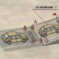
The search coils connected to it must be exactly the same in size and winding data. They must be positioned so that in the absence of foreign metal objects there is practically no connection between them; examples of coils are shown in the figure.

If the transmitter and receiver coils are positioned this way, the transmitter signal will not be heard in the receiver. When a metal object appears in the vicinity of this balanced system, under the influence of the alternating magnetic field of the transmitting coil, so-called eddy currents arise in it and, as a result, its own magnetic field, which induces an alternating EMF in the receiving coil.

The signal received by the receiver is converted by phones into sound. The metal detector circuit is really very simple, but despite this, it works quite well, and the sensitivity is not bad. The multivibrator of the transmitting unit can be assembled using other transistors of a similar structure.
The metal detector coils have a size of 200x100 mm and contain about 80 turns of 0.6-0.8 mm wire. To check the operation of the transmitter, connect headphones instead of the L1 coil and make sure that sound is heard in them when the power is turned on. Then, by connecting the coil in place, they control the current consumed by the transmitter - 5...8 mA.

The receiver is configured with the input closed. By selecting resistor R1 in the first stage and R3 in the second, a voltage equal to approximately half the supply voltage is set on the collectors of the transistors, respectively. Then, by selecting resistor R5, they ensure that the collector current of transistor VT3 becomes equal to 5...8 mA. After this, opening the input, connect the receiver coil L1 to it and, receiving the transmitter signal at a distance of about 1 m, make sure that the device is working.