To ensure ignition of a combustible mixture in the cylinders of a gasoline power plant, an external source is used - an electric spark that skipping the incandescent candles between the electrodes. But between these electrodes there is a certain gap, which the electrical voltage must break through. Therefore, a large value of tens of thousand volts should be supplied on the candle.
Classic ignition coil
Naturally, the onboard network of the car is not something that is not calculated, it is not even able to issue such a voltage, because there is no portable power source with such output parameters.
This problem was solved by inclusion in the ignition system of a special coil generating high voltage. In essence, the ignition coil is a device converting low value (6-12 V) in large values \u200b\u200b(up to 35,000 V).
This is the main function of this element - the generation of high voltage pulse, which is supplied.
It is achieved by the generation of voltage of significant testimony by the design. The ignition coil simply is simple, it consists of two types of windings.
The design of the ignition coil

Device of the ignition coil
Primary winding, it is low-voltage, takes the voltage that is separated from the battery or. It consists of a cooler coat, made of copper. Because of this, the number of turns of this winding is insignificant - up to 150 turns. To prevent possible voltage jumps and the occurrence of short circuit, this wire is covered with an insulating layer. Ends of this winding are removed on the cover of the coil, and the wiring with a voltage in 12 V. is connected to them.
The secondary winding is placed inside the primary. It consists of a fine cross section, which provides a large number of turns - up to 300,000. One of the ends of this winding is connected to the minus output of the first winding. The second output, which is positive, is connected to the central output of the coil. From this output, high voltage is fed.
Principle of operation of the ignition coil
The ignition coil works for this principle: the voltage that is separated from the power supply runs through the turns of the primary winding, which is why the magnetic field is formed, which affects the secondary winding. Due to this field, a high-value voltage pulse is formed in it. A large number of turns of this winding affect this value, since the induction of the magnetic field of the first winding is multiplied by the number of turns of the secondary winding. Hence the high output voltage.
To increase the magnetic field inside the coil, thereby providing a higher output voltage, an iron core is placed inside the coil.
Video: Individual Ignition Coil VAZ
Something useful for you:
Since during the coil operation, a current heating of the windings is possible, the transformer oil is used for cooling, which is filled with the cavity of the case. The cover is adjacent to the body hermetically, so the coil is inseparable. In the event of a malfunction, it is also not subject to repair.
The inlet and output voltage of the coil are not the main characteristics, with which you can check the serviceability of it. Checking the coil performance is carried out by resistance to its turns. At the same time, each of the coils resistance can be different. For example, the coil may have the resistance of the first winding at the level of 3.0 ohms, and the secondary - 7000-9000 ohms. Deviation when measured from these values \u200b\u200bwill indicate the coil malfunction. And since it is unrestracted, it simply is replaced.
Above the design of the general type coil was described. It is installed on all cars having a battery, contactless and electronic ignition system, and equipped with a distributor, which pulse from the coil sends to the desired cylinder.
Two-union coil
There are two more types of coils - two-unit and individual. Two-unit coils are used in the electron ignition system with direct spark in the candle.

Two-water coil. Very often used on motorcycles with electronic ignition system. A feature is the presence of two high-voltage conclusions. They can synchronously receive a spark from two cylinders.
Internal design it is almost no different from the general type coil. But the conclusions for supplying the pulse at such a coil - two. That is, when the coil is working, the impulse is served immediately into two candles. Since, when operating a power plant at the same time, the end of the compression tact in two cylinders cannot be, but only in one cylinder, then in the second spark discharge, which is slipped between the candles' electrodes will not carry any useful function - the ISROR idle. But with the further operation of the motor, the situation will change - in the second cylinder there will be an end to the tact of compression and the spark is necessary, and in the first cylinder it will be idle.
The two-unit coil can have different ways to connect to incandescent candles. One of the ways is the flow of pulses by means of two high-voltage wires. The second is the use of one tip and one high-voltage wire.
Such a coil allows you to do without a distributor, but it can only file a spark by two cylinders. And usually the car is used 4 cylinders. For such cars, a four-way coil is used, which in itself represents two two-unit coils combined into one block.
Individual ignition coil

Depending on the core device, individual ignition coils are divided into two types - compact, and rod
Compact (left) and rod (right) Individual ignition coils installed directly above the ignition candles.
The last type of coils used on cars are individual. Such coils work only with one, but when used from the transmitting spool of the chain, one of the elements is excluded - the high-voltage wire, since the coil is placed.
It has a slightly different design, but at the same time the principle of work remained unchanged.

Device of an individual ignition coil
It has two cores. Two windings are located on top of the internal. But in this coil, the secondary winding is located on top of the primary one. The outer core is located over the windings.
The outputs of the secondary winding are connected to the tip that dresses on the candle. This tip consists of a rod designed to work with high voltage, springs and an insulator.
In order to protect the windings from significant loads, a diode is connected, designed to work with a significant voltage.
This coil design is very compact, which makes it possible to use one element for each cylinder. And the absence of a number of other elements used in systems that are equipped with the first two types of coils can significantly reduce the loss of voltage in the chain.
This is all the ignition coils that are currently equipped with cars.
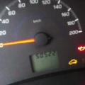
Watching the diagnosis of electrical equipment to a hundred, many want to know that it shows this or that picture on the Motoresther screen.
Fig. 1. Normal voltage values \u200b\u200bon a four-cylinder candlelight. |
|
Fig. 2. Oscillogram of voltage in the cord wires. |
|
|
|
Fig. 3. Plots "abnormal" oscillograms: A - breakdown voltage and spark duration too large; b - the breakdown voltage is too large and there is no burning area; V - voltage breakdown and spark below, and the spark duration above is normal. |


We continue to acquaint with the methods of diagnosing a car by amateur and professional measuring instruments (see SM, 1998, No. 10). As the magnitude of the high voltage, the developers of famous Minsk motors will tell the development of the ignition. More than 1000 devices created by this company are successfully operated at the enterprises of the car service of Russia, Belarus, Ukraine, the Baltic countries.
The work of all gasoline engines is based on the same physical processes, so many external parameters are very similar.
In order not to disrupt the operation of the ignition system, cutting into it when measuring high voltage, in the MotorTesters use a special capacitive type sensor. It can be represented as a second capacitor cover, the first planlaging of which is the central livel of the high-voltage wire, and the dielectric between the plates is insulation of the same wire. The tank formed in this way is sufficient to fix the voltage value, which is proportionally high. This picture is presented in Fig. 1, where the columns depict the voltage value in the high-voltage chain of each of the four cylinders. Here it is equally on all candles.
Recall the essence of the processes in the ignition system. Iighing the mixture in the engine is a spark that occurs between the electrodes of the candle. With the optimal gap between them (0.6-0.8 mm) and the normal composition of the fuel and air mixture in the schro-digit cylinder begins when the potential difference between the electrodes reaches about ten kilovolts (Fig. 2, yellow zone). Iskra breaks the space between the electrodes, the environment is ionized between them, and then the mixture is flammable.
The electrical resistance of the medium and the voltage between the electrodes at the last moment drops sharply to 1-2 kV (Fig. 2, red zone). After some time (0.7-1.5 milliseconds), at the end of the combustion process, the mixture becomes increasingly ionized particles near the electrodes, so the resistance of the medium increases and the voltage between the electrodes increases to 3-5 kV (Fig. 2, blue zone). This for breakdown is not enough, and high voltage, fluid in accordance with the fading transition processes in the ignition coil, falls to zero - until the next pulse (Fig. 2, green zone).
When the gap between the electrodes of the candle is less, then the breakdown occurs at less voltage. This is not the best option. The energy of sparks is less, worse conditions for the ignition of the mixture, and ultimately the power and economic characteristics of the engine are reduced.
If in the candle the gap is more norm, then the breakdown occurs, on the contrary, with a higher voltage. In energy, it seems to be not bad, but the probability of the breakdown of dielectric parts is growing (the distributor cover, "runner", candle insulator, etc.) and current leaks. This may at the most inappropriate moment lead to interruptions in the engine, the impossibility of it is impossible, especially in wet weather, etc.
If with a normal gap in the candlelight, the voltage is below the norm (only 4-6 kV), then it may be re-entered the mixture entering the cylinders. After all, than it is richer, the better spends the current - and, therefore, with a smaller voltage there will be a breakdown between the electrodes. So, you need to do a carburetor or injection system.
If, on the contrary, high voltage above the norm (for example, 13-15 kV) - the mixture is too poor. The engine can stop at idle, not to develop complete power, etc. Other reasons except the mixture: a break or absence of full contact in the central high voltage wire, the crack in the distributor cover, the runner break.
If high voltage is greater than the norm in one of the cylinders, then the air seats in this cylinder can be included in the number of possible reasons.
For complete diagnostics of the ignition system, two more parameters are important - voltage and spark duration. In the ideal case, the voltage is about 10 kV, and the duration is 0.7-1.5 milliseconds. These two parameters are closely related to each other, as they determine the energy of the spark. Since the energy accumulated by the coil is a permanent value, the more the voltage of the spark, the less its duration becomes, and vice versa. To analyze these parameters in detail, increase the scale on the MotorTesther screen.
If the breakdown and spark voltages are significantly higher, and the duration is more than 1.5 ms (the oscillogram looks like in Fig. 3, a), the reason can be found, checking the candles, "Runner", the distributor cover and the ignition coil.
If we see on the screen that the combustion area is generally absent (Fig. 3, b), the amplitude of the breakdown voltage above the norm and the high-voltage oscillating process goes (as a mirror repeating oscillations in the primary winding of the ignition coil) - it means that the wire going to the candle cylinder.
If the combustion process is observed, but the voltage of the breakdown and spark is two higher than the norms, and the oscillogram shows the oscillating process on the entire portion of the burning, it means that you need to look for a crack in the candle housing.
If, on the contrary, these voltages are significantly lower than the norm, the duration of the spark is greater than 2.5-3 ms, most likely breaks through the "mass" (short-range) high-voltage wire (Fig. 3, B).
Of course, we have deciphered only the most basic, most common options for indications and oscillograms of high voltages. Other, more complex are described in the manuals for the operation of motorsters.
The main function of the ignition system in the gasoline engine is the feeding of sparks on the spark plug during a certain tact of its operation. The ignition system of the diesel engine is arranged differently, it takes place when the fuel is injected into compression tact.
Views
Depending on how the process of forming a spark is, several systems are distinguished: non-contact (with the participation of the transistor), electronic (using a microprocessor) and contact.
Important! In the contactless scheme, to interact with the pulse sensor, a transistor switch that performs the function of the interrupter is used. High voltage adjusts the mechanical distributor.
The electronic engine ignition system accumulates and distributes electrical energy using an electronic control unit. Previously, the constructive feature of this option allowed the electronic unit to respond simultaneously for the ignition system and for the fuel injection system. Now the ignition system is an element of the engine control system.
In the contact system, electrical energy is distributed using a mechanical device - a distributor interrupter. The contact transistor system is engaged in further distribution.

Production of the ignition system
All types of car ignition system are different, but they still have common elements from which the system is formed:

Principle of operation
Consider a Read more ignition distributor to determine the technology of the direction of the electrical pulse to each cylinder separately. After removing the lid of the traver, you can see the shaft with the plate in the center and the copper contacts located in a circle. This plate is a slider, it is usually plastic or textolite and there is a fuse. The copper tip from one edge of the runner takes turns in turn concerns copper contacts, distributing electrical discharges on the wires to the cylinders at the required time of the engine work tact. While the slider performs its movement from one contact to another, a new portion of a combustible mixture for ignition is prepared in the cylinders.
Important! Exclude a constant flow of current, a trigger is installed in the rubber - the contact group. The cams are located on the shaft eccentric, and during rotation closure and unlock the electrical network.
A prerequisite for the proper operation and effective combustion of the mixture is the self-burning strictly at a certain point. The fire process is very complicated from a technical point of view, since a large number of arc discharges are formed in the cylinders, which depend on the engine speed. The discharges should also be equal to certain values: from 0.2 MJ and higher (depending on the fuel mixture). In case of insufficient energy, the mixture will not light up, and interruptions will appear in the engine operation, it may not start or stagged. The operation of the catalyst also depends on the health of the engine ignition system. If the system works with interruptions, the fuel residues will fall into the catalyst and get it there, which will lead to overheating and the extension of the catalyst metal both outside and the failure of the internal partitions. Furious inside the catalyst will not be able to perform its functions and will need to be replaced.

Possible malfunctions
Installation of various systems: contact, non-contact, electronic, on modern cars, still obeys the general rules, so you can select the following main ignition system malfunctions:
- non-working candles;
- coil does not work;
- a circuit compound (wire exhaust, contact oxidation, poor connection) is broken.
For the contactless engine ignition system, the switch is also characteristic of the switch, the distributor sensor cap, the vacuum of the traver, the Hall sensor.
Attention! The electronic control unit itself may fail. Also, malfunctioning input sensors will also be launched.

Signs
The most frequent causes of the breakage in the ignition system are:
- installation of low-quality spare parts (candles, coils, candle wiring, cam cam, distributor covers, sensors);
- mechanical damage to the components of parts;
- incorrect operation (low-quality fuel, non-professional maintenance).
Diagnose the malfunction of the ignition system is possible and by external features. Although symptoms may be similar to problems in the fuel system and injection system.
Tip! It will correctly diagnose these two systems in parallel.

Determine yourself that the breakdown concerns exactly the ignition, it is possible in the following external features:
- the engine starts not from the first starter twists;
- at idle (sometimes under load), the engine is unstable, as the masters say - the motor "Troit";
- engine pickup decreases;
- increases fuel consumption.
If there is no possibility to immediately contact the service, you can try to independently determine the cause of the failure and repair the ignition system, as some parts relative to consumables and are sold at any auto parts store. First of all, you can unscrew and check the candles. If the electrodes burned and the patches were formed between them, then it is necessary to replace the candles. To work, you will need one candle wrench and a new set of candles that are selected according to the necessary gap parameters and thread sizes.
Also in the dark or in a closed garage, you can open the hood and when piercing high-voltage wires to see the weak glow and sparking in one or more wires. Then they will need to replace them, which is easy to spend independently. The main thing is to choose the seller-consultant without difficulty, if you call it the machine brand.
The remaining types of diagnostics of the ignition system (verification of sensors, coils and other electronic devices) better entrust professionals.

Conclusion
With self-diagnostics, remember that it is impossible to touch the elements of the engine when it is running. Do not check in painting on the motor included. If the ignition is turned on, do not remove the switch plug connector, as it may fail the condenser.
To accurately detect a malfunction, you can use the oscilloscope with which to display the oscillogram of the entire ignition system. About how to use the device to know in the following video:
Without which the gasoline engine will never cost, it is without a spark, at the moment when you need to set fire to the fuel mixture in the cylinder. For this, a car ignition system has been created. It also calls the spark spark system.
The evolution of this system came from a simple contact system of ignition, then contactless, transistor, transistor appeared with the development of technical progress. And the crown of our time is the electronic ignition system.
All these ways to manage I spark we consider in articles.
In the meantime, we briefly run on the basic principles of each system.
The main node in this system is a dispenser. In this system, everything is mechanically occurring.
Contact group (interrupter), running through the protrusions of the cam shaft, interrupts the contacts. Depending on how the frequency of the shaft rotation, low voltage pulses are fed to the converter coil, the voltage is converted to high and fed to spark plugs.
This current is distributed to each cylinder, too, a mechanical node - distributor. Concomposed this node in one mechanism barrier-distributor (rubber)
Contact transistor ignition system
The next stage of the development of spar formation was the transistor high voltage control circuit.
The transistor, passing the low voltage, coming from the contact group, manages the operation of the current converter (coil) and converts them to the current up to 30 thousand volts, to obtain a powerful spark.
Such a system made it possible to reduce tension on contacts, increasing their service life. Allowed to increase the power of the spark and its stability, which, accordingly, affected the reliability and stability of the engine.
Contactless car ignition system
 In this ignition system, the role of the breaker performs a special switch that interacts with the sensor generates pulses of a low voltage control.
These pulses are then fed, as in the contact and contact and transistor systems, on the voltage converter (coil) and then through the mechanical distributor to the candles.
Such a system essentially excluded all mechanical contact when the current is interrupted. The contacts of the interrupter who delivered not little harm to motorists were not needed and therefore disappeared the need for their maintenance.
And the reliability and stability of the engine work increased at times. The power and environmental friendliness of gasoline engines increased.
But progress does not stand still, and with the development of electronics, the system of the highest level appeared - electronic.
Electronic ignition system
Such a system is already working together with other engine control systems.
 Numerous sensors monitor all modes of engine operation, down to the state of the exhaust gases, fix and give information the engine control unit.
The electronic control unit processes the signals and sends the control adjustment to the control transistor, which in turn exercises at the desired cut-off time in the primary winding of the coil. In the secondary winding, high voltage is presented and the spark is formed.
Sensors that follow the frequency of rotation of the crankshaft and the camshaft position sensors transmit information to the ECU, which is processed and the command is issued to the appropriate ignition advance angle.
Also, if the load increases the engine, the air flow sensor sends the command to the ECU, which calculates the optimal ignition advance angle to the appropriate load.
Such a system is perfect in all respects. It allows you to:
- use it on any carburetor engines;
- increase in one and a half times the spark voltage, the power of which will be up to 30 kilowatts, on any modes of engine operation;
- eliminate depreciation of interrupters;
- increase the gap on the contacts of the candles to 1.2 mm.;
- facilitate the plant in the cold season;
- excludes adjustment and preventive work.
The only drawback of such a system is the rise in price. Although it is worth it!
That's all, I hope it is clear what is a car ignition system.
Be healthy and watch out for publications!
The main conditions of smelting of the mixture are the excess of the high (secondary) voltage over the breakdown voltage and the sufficiency of the spark discharge energy, highlighted in the spark gap of the incendiary candle. Spark discharge has capacitive and inductive phases. The duration of the capacitive phase is small and amounts to 1-3 μs. Therefore, the energy allocated in this spark discharge phase ensures ignition of only a homogeneous and fully gasified working mixture. When starting a cold engine, when the steam verge of fuel in the mixture is not enough, and its temperature is low, it is required to inflate the working mixture in addition to the capacitive phase of the discharge. The duration of the inductive phase of the spark discharge is significantly larger than the capacitive, which helps to improve the heating of the mixture and its evaporation. This provides better ignition of the mixture in its composition at the boundaries of flammability.
The ignition systems intended for engines with E\u003e 9, the spark discharge energy reaches 0.05 J, and the duration of 2.5 ms. At the same time, the increase in secondary stress over the voltage of the breakdown characterized by the reserve coefficient is 1.4-1.5.
The magnitude of the breakdown voltage when starting the engine (especially cold) is always greater than on its operating modes. This is associated with the low temperature of the electrode of the candle and the working mixture in the cylinder. The breakdown voltage depends on the pressure of the compression at the time of the breakdown of the spark gap and the distance between the electrodes of the candle. The magnitude of the breakdown voltage is influenced by the form of the candle electrodes (the result of electric erosion), with a change in which it increases by 3-4 square meters for the first 25 thousand km of the car.
The value of the secondary voltage developed by the ignition system depends on the constructive and operational factors.
With starting frequencies of the engine crankshaft, the time of the closed state of the interrupter's contacts is sufficiently large enough, and the current strength in the primary electrocrepe reaches the maximum value. With a low frequency of opening the contacts and the high strength of the gap, induced in the primary winding of the coil, it is possible to break the spark air gap between the contacts, which causes the deterioration of the spark discharge parameters.
The secondary voltage decreases with a decrease in the voltage on the clips of the battery, which is determined by the low temperature of the battery and the degree of its discharge. To compensate for the voltage reduction in the primary electrical power supply systems, the domestic car introduces an additional resistor, closed by spice at the time of the starter.
It is necessary to note the effect of non-uniformity of electrostrometer scrolling of the crankshaft to reduce the secondary voltage of the ignition systems. The secondary voltage drops with an uneven scrolling of the crankshaft by 0.2-1.5 kV compared to uniform scrolling. Reducing the secondary voltage is possible with an increase in the shunt resistance and the gap between the electrodes. The shunting of the candles during the start of the engine occurs as a result of re-enrolling the mixture and entering moisture electrodes and the residues of combustion products. The largest shunting of candles is observed in rotary-piston engines (due to the design features of the candle location) and in two-stroke engines due to the poor organization of the process of mixing and poor cleaning of cylinders from residual gases. Increase the spark discharge energy and the value of the secondary voltage in the ignition systems can only be increased by an increase in the current of the inclusion current of the ignition coil. In classical electromechanical systems, such an opportunity is limited to the service life of the interrupter's contacts. The greatest operational reliability of contacts takes place at a current of 1 A.
The problem of the growth of secondary voltage and the energy of the spark discharge due to an increase in the current flow rate of the primary chain is solved using the contact-transistor and contactless ignition systems.
Provide easier conditions for the operation of the interrupter's contacts while simultaneously increasing the strength of the operating current of the primary chain.
The secondary voltage developed by the contact-transistor ignition system of the engine ZIL-508.1000400 is 25 kV, which provides the reserve coefficient of 1.7-1.8 (1.35 for the classical system). The current of the current in the primary chain of the ignition coil is about 7 A and the interrupter-tangible contacts - 0.7-0.9 A. The positive quality of the contact transistor system is an increase compared with the classical duration and energy of the spark discharge (energy up to 0.024-0.025 J and duration up to 2.0-2.3 ms). The disadvantages of these systems include an effect on their voltage characteristics in the primary chain and l, although it is somewhat less than that of the classical system.
The best systems from the point of view of the start are electronic contactless systems with electronic or electromechanical fibergiation automata machines that have contactless control of the ignition torque with a normalized energy accumulation time in a magnetic field. In such systems, the energy accumulation time is almost independent of n, which improves engine starting conditions. The energy of the inductive phase on the engine launchers for domestic electronic systems (contactless and microprocessor) is from 0.03 to 0.05 J, and the discharge duration of 2.0 to 1.7 ms.
Electronic systems with the accumulation of energy in the electrostatic field of the capacitor and the switched element (thyristor) are widely used. A sharp increase in secondary voltage provides low sensitivity to spark plug shunt. This nature of the increase in the voltage of the thyristor system, despite the low duration of the inductive component, allows to increase the reliability of ignition of fuel-oil mixtures of two-stroke and rotary-piston engines, as well as gas-air mixtures of gas engines.
Two-stroke engines are equipped with ignition systems from magneto, the feature of which are the lower secondary voltage and the energy of the spark discharge compared with the battery system of ignition, especially in the interval of the rotational speed of the crankshaft 200-300 min-1. To enhance the reserve coefficient on the secondary voltage, it is necessary to raise the starting frequency of rotation of the crankshaft, which worsens the economic indicators of the starting system.
The non-uniformity of the rotation of the crankshaft shaft of the starting engines during the electrostarity start (5 reaches 1.85-1.90) leads to a decrease in the secondary voltage by 0.3-4.5 square meters. This must be considered when choosing the parameters of ignition systems from magneto.
Improve starting engines can be improved due to the use of electronic ignition systems, the minimum frequency of sustainable sparking of which should be not more than 100-150 minutes