To ensure the ignition of the combustible mixture in the cylinders of a gasoline power plant, an external source is used - an electric spark that skips between the electrodes of the glow plug. But there is a certain gap between these electrodes, which the electric voltage must break through. Therefore, a high voltage must be supplied to the candle, amounting to tens of thousands of volts.
Classic ignition coil
Naturally, the on-board network of a car is not something that is not calculated, it is not even capable of producing such a voltage, since there is no portable power source with such output parameters.
This problem was solved by including a special coil in the ignition system that generates high voltage. In fact, an ignition coil is a device that converts low voltage (6-12 V) into high values \u200b\u200b(up to 35,000 V).
This is the main function of this element - the generation of a high voltage pulse supplied by the filament.
Achieved by the generation of voltage significant indications of the design. The ignition coil is arranged simply, it consists of two types of windings.
Ignition coil design

Ignition coil device
The primary winding, it is also low-voltage, accepts the voltage supplied from the battery or. It consists of coarse wire coils made of copper. Because of this, the number of turns of this winding is insignificant - up to 150 turns. To prevent possible power surges and short circuits, this wire is covered with an insulating layer on top. The ends of this winding are brought out to the coil cover, and wiring with a voltage of 12V is connected to them.
The secondary winding is placed inside the primary. It consists of fine wire, which provides a large number of turns - up to 30,000. One of the ends of this winding is connected to the negative terminal of the first winding. The second lead, which is positive, is connected to the center lead of the coil. From this pin, the high voltage is fed further.
The principle of operation of the ignition coil
The ignition coil works according to this principle: the voltage supplied from the power source passes through the turns of the primary winding, due to which a magnetic field is formed, which acts on the secondary winding. Thanks to this field, a high voltage pulse is formed in it. This value is affected by the large number of turns of this winding, since the magnetic induction of the first winding is multiplied by the number of turns of the secondary winding. Hence the high output voltage.
To increase the magnetic field inside the coil, thereby providing a higher output voltage, an iron core is placed inside the coil.
Video: Individual ignition coil VAZ
Something else useful for you:
Since during the operation of the coil, current heating of the windings is possible, transformer oil is used for cooling, which fills the cavity of the housing. Its cover adjoins the body hermetically, so the coil is non-separable. In the event of a malfunction, it is also not repairable.
The input and output voltage of the coil are not the main characteristics, with which you can check its serviceability. The performance of the coil is checked by the resistance of its coil. In this case, the resistance of each of the coils may be different. For example, a coil can have a first winding resistance of 3.0 ohms, and a secondary winding resistance of 7000-9000 ohms. Measurement deviation from these values \u200b\u200bwill indicate a coil malfunction. And since it is not repairable, it is simply replaced.
Above, a general type coil design has been described. It is installed on all cars that have a battery, contactless and electronic ignition system, and are equipped with a distributor that directs an impulse from the coil to the desired cylinder.
Dual lead coil
There are two more types of coils - dual-lead and individual. Dual lead coils are used in an electronic ignition system with a direct spark to the spark plug.

Dual lead coil. It is very often used on motorcycles with an electronic ignition system. A special feature is the presence of two high-voltage terminals. They can simultaneously receive a spark from two cylinders.
Its internal design practically does not differ from the general type coil. But such a coil has two conclusions for supplying an impulse. That is, when the coil is operating, an impulse is applied to two candles at once. Since when the power plant is operating simultaneously, the end of the compression stroke in two cylinders cannot be, but only in one cylinder, then in the second a spark discharge that will slip between the electrodes of the spark plug will not carry any useful function - an idle spark. But with further operation of the engine, the situation will change - in the second cylinder there will be the end of the compression stroke and a spark is needed, and in the first cylinder it will be idle.
The dual lead coil can be connected in different ways to the glow plugs. One way is to send pulses through two high voltage wires. The second is to use one tip and one high voltage wire.
Such a coil makes it possible to do without a distributor, but it can only supply a spark to two cylinders. And usually a car uses 4 cylinders. For such cars, a four-lead coil is used, which itself is two dual-lead coils combined into one unit.
Individual ignition coil

Depending on the core device, individual ignition coils are divided into two types - compact, and rod
Compact (left) and rod (right) individual ignition coils installed directly above the spark plugs.
The last type of reels used on auto is individual. Such coils work with only one, but when they are used, one of the elements is excluded from the spark-transmitting circuit - the high-voltage wire, since the coil is placed.
It has a slightly different design, but the principle of operation has remained unchanged.

Individual ignition coil device
It has two cores. On top of the inner one there are two windings. But in this coil, the secondary winding is located on top of the primary. The outer core is positioned over the windings.
The outputs of the secondary winding are connected to the tip, which is put on the candle. This ferrule consists of a high voltage bar, a spring and an insulator.
To protect the windings from significant loads, a diode is connected to the secondary, designed to work with significant voltage.
This coil design is very compact, which makes it possible to use one element per cylinder. And the absence of a number of other elements used in systems that are equipped with the first two types of coils can significantly reduce voltage losses in the circuit.
This and all currently produced ignition coils that are equipped with cars.
Ignition systems are compared according to the following characteristics:
Dependences of the secondary voltage U 2 m on the discharge frequency f ;
Power consumption;
The duration of the spark discharge (inductive component);
The rate of rise of high voltage, which determines the sensitivity of the ignition system to shunting the spark plug gap;
Reliability of the ignition system;
Service needs;
The presence of toxic substances in the exhaust gases.
The greatest value of the above characteristics is the dependence of the secondary voltage U 2 m on frequency f.
Discharge frequency is proportional to rotation frequency n and the number of cylinders of engines
where τ equals 2 for 4-stroke engines and 1 for 2-stroke engines.
In fig. 4.8 shows the dependence of the secondary voltage developed by various ignition systems on the frequency of discharges (sparking). The largest decrease in the secondary voltage (Fig. 4.8, curve 1) with an increase in the sparking frequency occurs in the contact battery (classical) ignition system due to a decrease in the rupture current in the primary winding of the ignition coil. The maximum discharge frequency of the contact battery ignition system is 300 sparks per second. This ignition system also lowers the secondary voltage when the engine is started.
Figure: 4.8. Dependence of the secondary voltage of various ignition systems on the discharge frequency: 1 - contact battery (classical); 2 - contact-transistor; 3 - thyristor (capacitor).
Contact-transistor ignition systems, due to a clear rupture of the increased current (up to 10 A) of the primary circuit, develop a higher secondary voltage and an increased uninterrupted frequency of discharges - 350 sparks per second.
In thyristor ignition systems, the secondary voltage does not depend on the discharge frequency, since the storage capacitor has time to charge up to the maximum (calculated) voltage (the discharge frequency is about 600 sparks per second).
Shunting the spark plug gap due to dirt and carbon deposits on the insulator leads to a decrease in the secondary voltage. The most resistant to shunting the spark gap is the thyristor ignition system (Fig. 4.9, curve 1) due to the rapid rise in the secondary voltage. The contact battery (classic) ignition system loses most of all voltage when shunting the spark gap (Fig. 4.9, curve 3).
Figure: 4.9. Percentage change in the secondary voltage depending on the shunt resistance of the spark gap of the spark plug in various ignition systems: 1 - thyristor; 2 - contact-transistor; 3 - contact battery (classic)
The power consumed by different ignition systems is not the same, and with a change in the engine speed, it does not remain constant.
The greatest power is consumed by the contact-transistor ignition system (about 60 W) at the starting speed, and at the maximum speed it decreases to 40 W. The contact battery ignition system has a reduced power consumption (18 - 20 W at starting and 7 - 9 W at maximum speed).
The decrease in power consumption by the above-mentioned ignition systems occurs due to a decrease in the burst current with an increase in the engine speed.
The most laborious in maintenance is the contact battery (classical) ignition system. Malfunctions in it appear after about 10,000 km of run.
The duration of the spark discharge between the spark plug electrodes characterizes its energy and has a significant effect on the completeness of combustion of the working mixture, and, consequently, on the composition of the exhaust gases. The allowable discharge time is considered from 0.2 to 0.6 ms. When the discharge time is less than 0.2 ms, the engine start-up deteriorates, and when the discharge duration is more than 0.6 ms, the electrical erosion of the spark plug electrodes increases. The larger the spark gap between the spark plug electrodes, the shorter the discharge duration.
The voltage supplied to the primary winding of the ignition coil of capacitor ignition systems must be in the range of 290 - 400 V, since the secondary high voltage is associated with the voltage in the primary winding through the transformation ratio of the ignition coil and if the primary voltage deviates below 290 V, the ignition will not be reliable, and if the deviation is higher than 400 V, the insulation of the winding of the ignition coil or the distributor cover may be broken.
The desire to improve their vehicle, probably, never left their owners, so there is nothing strange in the fact that along with the modernization of other units and systems of the car, the turn came to its ignition. Domestic cars and many old foreign cars have a contact type of ignition system, however, recently, more and more often you can hear about another type of it - contactless ignition.
Of course, on this score, everyone has different opinions, however, most motorists are inclined towards this option. In this article, we will try to find out what the contactless system owes to such popularity, what it consists of and how it functions, and also consider the main types of possible malfunctions, their causes and first signs.
Advantages of contactless ignition

Most of the cars produced today with gasoline engines (no matter whether they are domestic or foreign) are equipped with no contacts in the design of the distributor breaker. Accordingly, these systems are called so - contactless.
The advantages of contactless ignition have already been tested in practice by more than one car owner, as evidenced by discussions of this topic on various Internet forums. For example, one cannot fail to note the simplicity of its installation and adjustment, its operational reliability, or the improvement in engine starting qualities in cold weather. Agree, the result is already a good list of "pluses". Perhaps this will not seem enough to car owners of more conservative views, but if you are thoroughly bothered by the frequent malfunctions of the "contact pair" and you began to think about replacing it with a more modern design of contactless ignition, then it is quite possible that this article will help you take this last and most crucial step. ...
According to some visitors, the same Internet forums, the biggest problem of replacing contact ignition with contactless is the process of buying a kit itself. Considering that it costs a lot, and depending on the brand and model, the price can differ significantly, not every car owner can force himself to spend this money. Here, as the saying goes: “who is counting on what” ... But I think you, dear readers, will be interested in what advantages specialists have found in this system. From their point of view, a contactless ignition system (in comparison with a contact one) has three main advantages:
At first, the supply of current to the primary winding is carried out through a semiconductor switch, and this allows you to get much more spark energy, by possibly obtaining a higher voltage on the secondary winding of the same coil (up to 10 kV);
 Secondly, an electromagnetic impulse creator (most often implemented on the basis of the Hall effect), which from a functional point of view replaces the contact group (CG) and, in comparison with it, provides much better impulse characteristics and their stability over the entire range of motor revolutions. As a result, a motor equipped with a contactless system has a higher level of power and significant fuel economy (up to 1 liter per 100 kilometers).
Thirdly, the need for maintenance of contactless ignition occurs much less often than a similar requirement for a contact system. In this case, all the necessary actions are reduced only to lubricating the distributor shaft, after every 10,000 kilometers.
However, not everything is so rosy and this system has its drawbacks. The main drawback lies in lower reliability, especially when it comes to switches of the original configuration of the described system. Quite often, they fail after several thousand kilometers of the car's run. A little later, a more advanced, modified switch was developed. Although its reliability is considered somewhat superior, globally, it can also be called low. Therefore, in any case, in a contactless ignition system, it is worth avoiding the use of domestic switches, it is better to give preference to imported ones, because in case of a breakdown, diagnostic procedures, and even the system repair itself, will not be particularly simple.
If desired, the car owner can upgrade the installed contactless ignition, which is expressed in replacing the system elements with better and more reliable ones. So, if necessary, the distributor cover, slider, Hall sensor, coil or switch must be replaced. In addition, the system can be improved by using an ignition unit for contactless systems (for example, "Octane" or "Pulsar").
 In general, in comparison with the contact ignition system, the contactless version works much clearer and more evenly, and this is due to the fact that in most cases, the Hall sensor acts as a pulse exciter, which is triggered as soon as air gaps pass by it (the slots in the rotating floor cylinder on the machine distributor axis). In addition, for the operation of electronic ignition (it is often referred to as its non-contact form), much less battery energy is required, that is, with a push, the car can be started even with a highly discharged battery. With the ignition on, the electronic unit practically does not use energy, but begins to consume it only when the motor shaft rotates.
A positive aspect of the use of contactless ignition is that it is unnecessary to clean or adjust it, in contrast to the same mechanical one, which not only requires more maintenance, but also draws direct current when the breaker contacts are closed, thereby contributing to the heating of the ignition coil when the engine is off ...
Structure and function of contactless ignition
The non-contact ignition system, also called the logical continuation of the contact-transistor system, only in this version, the place of the contact breaker was taken by the contactless sensor. In its standard form, the contactless ignition system is installed on a number of cars of the domestic auto industry, and can also be installed individually, independently - as a replacement for the contact ignition system.
From a constructive point of view, such an ignition has combined a number of elements, the main of which are presented in the form of a power source, an ignition switch, a pulse sensor, a transistor switch, an ignition coil, a distributor and spark plugs, and using high-voltage wires, distribute is connected to candles and ignition coil.
 In general, the device of a contactless ignition system corresponds to a similar contact one, and the only difference is the absence of a pulse sensor and a transistor switch in the latter. Pulse sensor(or pulse generator) is a device designed to create low voltage electrical impulses. There are the following types of sensors: Hall, inductive and optical. Structurally, the pulse generator is combined with the distributor and forms a single device with it - distributor sensor. Outwardly, it is similar to the distributor chopper and is equipped with the same drive (from the engine crankshaft).
The transistor switch is designed to interrupt the current in the primary winding circuit of the coil, in accordance with the signals from the pulse sensor. The interruption process is carried out by opening and closing the output transistor.
Signal conditioning by Hall sensor
In most cases, for a contactless ignition system, it is characteristic to use a magnetoelectric impulse sensor, the operation of which is based on the Hall effect. The device got its name in honor of the American physicist Edwin Herbert Hall, who in 1879 discovered an important galvanomagnetic phenomenon, which is of great importance for the subsequent development of science. The essence of the discovery was as follows: if a semiconductor with a current flowing along is influenced by a magnetic field, then a transverse difference in potentials (Hall EMF) will appear in it. In other words, applying a magnetic field to a plate of a conductor with a current, we get a transverse voltage. The emerging transverse EMF can have a voltage only 3V lower than the supply voltage.
The device provides for the presence of a permanent magnet, a semiconductor plate with an existing microcircuit and a steel screen with slots (another name is "shutter").
 This mechanism has a slotted design: on one side of the slot there is a semiconductor (when the ignition is on, current flows through it), and on the other, there is a permanent magnet. A cylindrical steel screen is installed in the sensor slot, the design of which is distinguished by the presence of slots. When the cut of the steel screen passes the magnetic field, a voltage appears in the semiconductor wafer, but if the magnetic field does not pass through the screen, accordingly, no voltage occurs. The periodic alternation of the cuts of the steel screen creates pulses that have a low voltage.
During the rotation of the screen, when its slots fall into the slot of the sensor, the magnetic flux begins to act on the semiconductor with a flowing current, after which the control pulses of the Hall sensor are transmitted to the switch. There they are converted into pulses of current in the primary winding of the ignition coil.
Malfunctions in the contactless ignition system
In addition to the ignition system described above, the contact and electronic systems are also installed on modern cars. Of course, during the operation of each of them, various malfunctions arise. Of course, some of the breakdowns are individual for each system, however, there are general breakdowns that are specific to each type. These include:
- problems with spark plugs, coil malfunctions;
Loose and low voltage connections (including broken wires, oxidized contacts, or loose connections).
If we talk about the electronic system, then this list will also include malfunctions of the ECU (electronic control unit) and breakdowns of the input sensors.
In addition to general malfunctions, problems in the contactless ignition system often include malfunctions in the device of the transistor switch, centrifugal and vacuum ignition timing regulator or distributor sensor. The main reasons for the appearance of certain malfunctions in any of the indicated types of ignition include:
- the unwillingness of car owners to comply with the operating rules (use of low-quality fuel, violation of the regularity of maintenance or unqualified maintenance);
Application in operation of low-quality elements of the ignition system (spark plugs, ignition coils, high-voltage wires, etc.);
The negative impact of external environmental factors (atmospheric phenomena, mechanical damage).
 Of course, any malfunction in the car will affect its operation. So in the case of a contactless ignition system, any breakdown is accompanied by certain external manifestations: the engine start does not start at all or the engine starts to work with difficulty. If you notice this sign in your car, then it is quite possible that the reason should be sought in a break (breakdown) of high-voltage wires, a breakdown of the ignition coil, or in a malfunction of the spark plugs.
Engine idling is unstable. Possible malfunctions characteristic of this indicator include a breakdown in the cover of the distributor sensor; problems in the operation of the transistor switch and a malfunction in the sensor-distributor.
An increase in gasoline consumption and a decrease in the power of the power unit may indicate a failure of the spark plugs; breakdown of the centrifugal ignition timing controller or malfunctions of the vacuum ignition timing controller.
The working mixture in the engine cylinder ignites from an electric spark that skips at the right moment. To ensure timely ignition of the working mixture, an ignition system is designed, which is of three types:
contact;
contactless (transistor);
electronic.
We can say that the time of contact and non-contact systems is practically gone. In modern cars, as a rule, an electronic ignition system is used. However, given the fact that many of our compatriots drive Soviet and old Russian cars, we will briefly consider the principles of operation of contact and transistor ignition systems. The latter, in particular, is used on the VAZ-2108. As for the electronic ignition system, in practice there is no need to study it, since the electronic ignition can only be adjusted at a specialized service station.
An electrical spark in a contact ignition system is generated between the spark plug electrodes at the end of the compression stroke. Since the gap of the compressed working mixture between the spark plug electrodes has a high electrical resistance, a high voltage must be created between them - up to 24,000 V: only in this case a spark discharge will be caused. By the way, spark discharges should appear at a certain position of the pistons in the cylinders and alternate in accordance with the established order of operation of the cylinders. In other words, the spark should not skip during the intake, compression or exhaust stroke.
The battery ignition contact system consists of the following elements:
sources of electric current (battery and generator);
ignition coils;
ignition lock (the driver inserts the key into it to start the car);
low voltage current breaker;
high voltage current distributor;
capacitor;
spark plugs (based on one cylinder - one spark plug);
electrical wires of low and high voltage.
Sources of electric current provide it to the ignition system. When starting the engine, the battery is the source. The running engine is constantly recharged from the generator.
The main purpose of the ignition coil (located in the engine compartment) is to convert low voltage current into high voltage current. When an electric current passes through the primary low voltage winding, a powerful magnetic field is created around it. After the current supply is stopped (this task is performed by the interrupter), the magnetic field disappears and crosses a large number of turns of the high voltage secondary winding, as a result of which a high voltage current arises in it. A significant increase in voltage (from 12 to the required 24,000 V) is achieved due to the difference in the number of turns in the coil windings.
The resulting voltage makes it possible to overcome the space between the electrodes of the spark plug and obtain an electrical discharge, as a result of which the required spark is formed.
Note: The average gap between spark plug electrodes is 0.5-1 mm. If necessary, it can be adjusted by unscrewing the candle.
If the gap between the spark plug electrodes is not adjusted, the engine runs unstable: not all cylinders may function. For example, out of 4 cylinders, 3 work, another 1 is spinning "idle" (in such cases, they say that the motor is troit). At the same time, the engine loses power noticeably, and fuel consumption increases.
By adjusting the gap between the spark plug electrodes, only the side electrode is bent. Do not bend the center electrode, as this can cause cracks in the ceramic insulator of the plug and it will become unusable.
The functions of the ignition switch are familiar even to beginners: it is necessary to close the electrical circuit and start the car.
The task of the low voltage breaker is to interrupt the supply of low voltage current to the primary winding of the ignition coil in time, so that at this moment a high voltage current is generated in the secondary winding. The generated current flows to the central contact of the high voltage current distributor.
The breaker contacts are located under the ignition distributor cover. The movable contact is constantly pressed against the fixed contact by means of a special leaf spring. These contacts open for a very short period of time at the moment when the oncoming cam of the distributor drive roller presses on the movable contact hammer.
So that the contacts do not fail prematurely, a capacitor is used, which protects the contacts from burning. The fact is that at the moment of opening the movable and fixed contacts, a powerful spark could slip between them, but the capacitor absorbs almost the entire electrical discharge.
Another task of the capacitor is to help increase the voltage in the secondary winding of the ignition coil. When the movable and fixed contacts of the breaker are opened, the capacitor is discharged and creates a reverse current in the low voltage coil, which accelerates the disappearance of the magnetic field. In accordance with the laws of physics, the faster the magnetic field disappears in the primary winding, the more powerful current occurs in the secondary winding.
This function of the capacitor is extremely important. After all, if it is faulty, the car engine may not work at all, since the voltage arising in the secondary winding will not be enough to breakdown the gap between the spark plug electrodes and, therefore, to produce a spark.
The low voltage current breaker and the high voltage current distributor are combined in one housing and represent a device called a distributor. Its main elements:
cover with contacts;
traction;
vacuum regulator body;
diaphragm of the vacuum regulator;
distributor rotor (slider);
base plate;
resistor;
contact coal;
centrifugal regulator with plate;
breaker cam;
movable breaker plate;
weight;
contact Group;
drive roller.
With the help of a rotor and a cover, the high voltage current generated in the ignition coil is distributed over the engine cylinders (more precisely, over the spark plugs in each cylinder). Further, the current flows through the high-voltage wire to the central contact of the distributor cover, and then through the spring-loaded contact angle to the rotor plate (slider). The rotor rotates, and the current passes through a small air space to the side contacts of the distributor cover. High-voltage wires are connected to these contacts, which conduct current to the spark plugs. Moreover, the wires with the contacts are connected in a strictly defined sequence, with the help of which the order of operation of the cylinders of the internal combustion engine is established.
In most cases, the sequence of operation of 4-cylinder engines is as follows: first, the working mixture ignites in the first cylinder, then in the third, then in the fourth, and finally in the second. With this order, the load on the crankshaft is evenly distributed.
The high voltage current must flow to the spark plug not at the moment when the piston has reached top dead center, but a little earlier. The pistons in the cylinders move at a very high speed, and if a spark appears at the moment the piston is in the upper state, the burnt working mixture will not have time to put the necessary pressure on it, which will lead to a noticeable loss of engine power. If the mixture ignites a little earlier, then the piston will experience the greatest pressure, therefore, the engine will show maximum power.
When exactly should the spark appear? This parameter is called the ignition timing: the piston does not reach approximately 40-60 ° to the top dead center, if measured by the angle of rotation of the crankshaft.
To adjust the initial ignition timing, the distributor housing is turned until the optimal option is found. At the same time, the moment of opening of the movable and stationary contacts of the breaker is selected when they either approach or move away from the oncoming cam of the drive roller of the distributor. By the way, the distributor is driven by the engine crankshaft.
In different operating modes of the engine, the combustion conditions of the working mixture change, so the ignition timing needs to be constantly adjusted. Two devices help to solve this problem: centrifugal and vacuum ignition timing controllers.
The centrifugal ignition timing controller consists of two weights on the axles, mounted on the drive shaft plate. The weights are pulled together by two springs. In addition, they have pins that are inserted into the slots in the breaker cam plate. The main purpose of the centrifugal ignition timing controller is to change the moment a spark appears between the spark plug electrodes, depending on the speed at which the engine crankshaft rotates.
As the crankshaft rotational speed increases, the weights under the action of centrifugal force diverge to the sides and rotate the plate with the breaker cam in the direction of its rotation by a certain angle, which ensures earlier opening of the breaker contacts. Therefore, the ignition timing is increased.
When the crankshaft rotational speed decreases, the centrifugal force also decreases. Under the action of clamping springs, the weights converge, turning the plate with the breaker cam in the opposite direction. The result is a reduction in the ignition timing.
A vacuum regulator is designed to automatically change the ignition timing depending on the current load on the engine. As you know, depending on the state of the throttle valve, a mixture of different composition enters the engine cylinders, respectively, it takes different time for its combustion.
The vacuum regulator is mounted in the distributor, and the regulator body is divided by a diaphragm into two cavities, one of which communicates with the atmosphere, the other through a tube with a carburetor (more precisely, with a throttle space). When the throttle valve is closed, the vacuum in the vacuum regulator increases, the diaphragm, overcoming the resistance of the return spring, bends outward and, through a special rod, turns the movable disk towards the rotation of the breaker cam in the direction of increasing the ignition timing. When the throttle valve opens, the vacuum in the cavity decreases, the diaphragm, under the influence of the spring, bends in the opposite direction, turning the chopper disk in the direction of rotation of the cam in the direction of decreasing the ignition timing.
On old Soviet and Russian cars, you can manually adjust the ignition using an octane corrector.
The key element of a car's ignition system is the spark plug. No matter what car you drive - Mercedes, Zhiguli, Lexus or Zaporozhets - you cannot do without candles. Recall that the number of spark plugs corresponds to the number of engine cylinders.
When a high voltage current enters the spark plug from the distributor, an electric discharge jumps between its electrodes, igniting the working mixture in the cylinder. During combustion, the working mixture presses on the piston, which, under the force of pressure, moves down and scrolls the crankshaft, from which torque is transmitted to the drive wheels of the car.
As for the contactless (transistor) ignition system, its main advantage is the ability to increase the power of the voltage supplied to the spark plug electrodes. This greatly simplifies the cold start of the engine, as well as its operation in the cold season. In addition, a vehicle with a contactless ignition system is more economical.
The main elements of a contactless ignition system are:
sources of electric current (battery and generator);
ignition coil;
spark plug;
distributor sensor;
switch;
ignition switch;
high-voltage and low-voltage wires.
A characteristic feature of the transistor system is that there are no breaker contacts, instead of which a special sensor is used. It sends pulses to the switch, which controls the ignition coil. The ignition coil converts the low voltage current into high voltage current as usual.
Among the most common malfunctions of the car ignition system, first of all, it should be noted late or early ignition, interruptions in one or more cylinders, as well as a complete lack of ignition.
If you notice that the engine is losing power and overheating at the same time, late ignition may be to blame. When the loss of power is accompanied by a characteristic thud in the engine, it is most likely an early ignition. In any case, to solve the problem, it is necessary to adjust the ignition timing (as motorists say, set the ignition). In modern cars, it is almost impossible to do this on your own, so immediately contact a service station.
If a cylinder is intermittent (the motor is troit) - first of all, check the condition of the spark plug: it is possible that carbon deposits have formed on its electrodes, which must be removed or the gap between the electrodes must be adjusted. In addition, the cause of the spark plug malfunction is the presence of cracks and other mechanical damage on the ceramic insulator.
Note: The candle is one of those parts that rarely need to be replaced. On average, a spark plug can "travel" several tens of thousands of kilometers, so the cause of such problems is not necessarily a plug malfunction.
Even an inexperienced motorist can replace spark plugs. To do this, disconnect the high-voltage wires from them, then unscrew the old candles with a special spark plug wrench and screw in the new ones. The operation is simple, it is performed literally in 10-20 minutes.
Sometimes it is difficult to determine by eye which spark plug is faulty (that is, which cylinder is working intermittently). To find damage, one by one disconnect the high-voltage wires from the corresponding spark plugs by removing their tips: if the engine interruptions become more noticeable, this spark plug is in good order, and if the engine operation has not changed, it means that it has failed. An additional confirmation of the malfunction of the spark plug may be that it will be colder than the rest after unscrewing it from a hot engine.
Damage to the high-voltage wire occurs, as a result of which electricity is supplied intermittently or not at all. It is recommended to check the state of the contact by which the wire connects to the candle: it happens that to eliminate the malfunction, it is enough to press it tightly. In older cars with a contact ignition system, the problem may lie in the corresponding socket of the breaker-distributor cover.
If there are interruptions in the operation of different cylinders, check the condition of the central high-voltage wire: there is a possibility of damage to the insulation. Perhaps this is due to a failed capacitor, poor contact of the high-voltage wire with the terminal of the ignition coil or the socket of the breaker-distributor cover (in cars with a contact ignition system). In old cars, the reasons may be burning of the breaker contacts, intermittent short to ground of the breaker movable contact due to damaged insulation, cracks on the distributor cover, unregulated gap between breaker contacts.
Spark problems are solved by spraying the ignition distributor and high-voltage wires with a water-displacing spray. An assortment of such aerosols is sold in car markets and in specialized stores. In particular, the VD-40 aerosol is popular among domestic motorists.
A rather unpleasant symptom is the complete absence of ignition. As a rule, the reason lies in malfunctions of high-voltage or low-voltage circuits. To eliminate them, you will have to contact a service station.
Attention: If you perform maintenance and repair work on the ignition system yourself with the engine running, do not touch the ignition system elements with your hands, and also do not check their performance "for a spark". When the ignition is on, the plug connector must not be disconnected from the switch, as this may damage the capacitor. Do not lay high-voltage and low-voltage wires in the same bundle.
© A. Pakhomov (aka IS_18, Izhevsk)
The main task of the ignition system of a modern gasoline engine is to generate high voltage pulses required to ignite the fuel-air mixture. The initial ignition of the mixture occurs from the energy released in the breakdown cord. In the bulk of the cord, an electric spark causes an almost instantaneous thermal heating of the molecules of the mixture, their ionization and a chemical reaction between them. If the energy released during this is enough to start the combustion reaction of the mixture in the remaining volume of the combustion chamber, then the mixture will ignite and the cylinder will work normally. Otherwise, misfire may occur. Therefore, the ignition system plays one of the key roles in ensuring reliable ignition of the fuel-air mixture.
Checking the elements of the ignition system is a mandatory operation when carrying out diagnostic work. It includes a fairly extensive list of actions using a variety of techniques. The latter include the analysis of the oscillogram of high-voltage breakdown and spark combustion, obtained with the help of a motor tester.
Let us briefly recall the characteristic moments of this oscillogram:
The accumulation time is the time during which energy is accumulated in the magnetic field of the coil. It is determined by the control unit in accordance with the program embedded in it or by the ignition switch. Once upon a time, the accumulation time depended on the angle of the closed state of contacts, but such systems are already hopelessly outdated, and will not be considered by us. Burning time is the time the current exists between the electrodes of the candle. Depends on many factors and is 1 ... 2 ms.

At the moment of opening the primary circuit of the ignition system, a high-voltage pulse is generated in the secondary coil. The voltage value at which the spark gap breaks down is called the breakdown voltage. When analyzing the waveform, this value must be measured and evaluated. Let's talk about how this can be done, what it will depend on.
The most important thesis that must be voiced before continuing the conversation is the following: the ignition system of a modern engine is part of the engine management system, the actuator of this system.
What is the fundamental difference between a modern system and a system with centrifugal and vacuum regulators, known from classic VAZ cars? The difference lies in the most important thing. If earlier the list of tasks of the ignition system included the formation of the energy storage time in the coil and the adjustment of the ignition timing depending on the crankshaft speed and engine load, then the function of the modern ignition system is only to generate high-voltage pulses and distribute them to the engine cylinders. The task of calculating the optimal UOZ and accumulation time is assigned to the electronic engine control unit. For a competent analysis of the oscillograms, it is necessary to clearly understand how the engine management system functions in terms of controlling the ignition system.
For a correct understanding of diagnostic techniques, you need to know the principle of operation of one or another element, see the cause-and-effect relationships, and first of all, it is absolutely necessary to have an idea of \u200b\u200bhow the spark gap breaks down.
Let us consider in a simplified form the mechanism of the breakdown cord formation. In general, gases and their mixtures are ideal insulators. But as a result of the action of ionizing cosmic radiation, free electrons are always present in the air and, accordingly, positively charged ions - the remains of molecules. Therefore, if the gas is placed between two electrodes and a voltage is applied to them, an electric current will arise between the electrodes. However, the magnitude of this current is very small due to the small number of electrons and ions.
The option under consideration is ideal. A uniform electric field is formed between flat electrodes located at a small distance from each other. A field is called homogeneous, the intensity of which at any point remains unchanged. Inside the spark gap, electrons move towards a positively charged electrode, gaining acceleration due to the action of an electric field on them. At a certain value of the voltage on the electrodes, the kinetic energy acquired by the electron becomes sufficient for the impact ionization of molecules.
This is explained by the figures:
 | |
|
| Fig. 3 | Fig. 4 | |
| Free electron 1 (Fig. 3), upon collision with a neutral molecule, splits it into electron 2 and a positive ion. Electrons 1 and 2 upon further collision with neutral molecules split them again into electrons 3 and 4 and positive ions, etc. A similar phenomenon occurs when positively charged ions move (Fig. 4).An avalanche-like multiplication of positive ions and electrons occurs when positive ions collide with neutral molecules. |
||
Thus, the process is increasing, and ionization in the gas quickly reaches a very high value. This phenomenon is quite similar to an avalanche in the mountains, for the origin of which an insignificant lump of snow is enough. Therefore, the described process was called an ion avalanche. As a result, a significant electric current arises between the electrodes, which creates a highly heated and ionized channel. The temperature in the channel reaches 10,000 K. The voltage at which the ion avalanche occurs is the previously considered breakdown voltage. It is designated Upr. After the breakdown, the channel resistance tends to zero, the current reaches tens of amperes, and the voltage drops. Initially, the process takes place in a very narrow zone, but due to the rapid increase in temperature, the breakdown channel expands at a supersonic speed. In this case, a shock wave is formed, which is perceived by ear as a characteristic crackle.
From a practical point of view, the most important is the value of the breakdown voltage, which can be measured and evaluated after obtaining the oscillogram. Let's analyze the factors on which it depends.
one . It is quite obvious that the value of the breakdown voltage will be influenced by the distance between the electrodes. The greater the distance, the lower the electric field strength in the space between the electrodes, the less kinetic energy charged particles will acquire when moving. And accordingly, other things being equal, a greater value of the applied voltage will be required for the breakdown of the spark gap.
2. The lower the concentration of gas molecules in the spark gap, the smaller the number of molecules per unit volume, and the longer the way charged particles fly freely between two successive collisions. Accordingly, the greater the amount of kinetic energy they store in the process of motion, and the higher the probability of subsequent impact ionization. Therefore, the breakdown voltage increases with increasing concentration of gas molecules. In practice, this means that the breakdown voltage increases with increasing pressure in the combustion chamber.
3. To solve diagnostic problems, it is important to know the dependence of the breakdown voltage on the presence of hydrocarbon molecules in the air, that is, fuel. In general, fuel molecules are dielectric. But they are long hydrocarbon chains, the destruction of which in an electric field occurs earlier than the relatively stable diatomic molecules of atmospheric gases. As a consequence, an increase in the number of fuel molecules (mixture enrichment) leads to a decrease in the breakdown voltage.
4 . The breakdown voltage will be significantly influenced by the shape of the spark plug electrodes. In the ideal case considered above, it was assumed that the electrodes are flat and the electric field arising between them is uniform. In reality, the shape of the spark plug electrodes is different from the plane, which causes an inhomogeneous structure of the electric field. It can be argued that the value of the breakdown voltage will largely depend on the shape of the electrodes and the electric field generated by them.
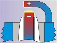 5 . The breakdown voltage of a real spark plug will depend on the polarity of the applied voltage. The reason for this phenomenon is as follows. When the metal is heated to a sufficiently high temperature, free electrons begin to leave the crystal lattice of the metal. This phenomenon is called thermionic emission. An electron cloud is formed, indicated in the figure in yellow. Due to the fact that the central electrode of the spark plug has a higher temperature than the lateral one, thermionic emission from its surface is more pronounced. Therefore, applying a positive potential to the side electrode will lead to breakdown of the spark gap at a lower voltage than in the opposite case.
6. Since the considered breakdown process occurs in the combustion chamber of a real engine, the nature of the movement of gases in the combustion chamber, their temperature and pressure at the moment of sparking, the material and temperature of the spark plug electrodes, as well as the design features of the ignition system used will have an effect on the breakdown voltage.
7. The following fact is also interesting in the applied sense. Positively charged ions are the nuclei of molecules and have significant mass. It is known from the physics course that practically the entire mass of a molecule is contained in the nucleus, and the mass of an electron is negligible in comparison with the nucleus. Ions, reaching the negative electrode, receive an electron and turn into a neutral molecule, but at the same time they bombard the electrode, destroying its crystal lattice. In practice, this translates into electrode erosion. The positive electrode is subject to less destruction because it is bombarded by low-mass electrons.
And finally, let's consider another important point that you should always keep in mind when analyzing a high voltage oscillogram. Let's refer to the figure.

It shows a graph of the pressure in the cylinder versus the crankshaft angle in the absence of ignition. Suppose that the sparking moment corresponds to the ignition timing of the UOZ 1. The pressure in the cylinder will be P1. Accordingly, at the moment of UOZ 2, the pressure will be equal to P2. It is quite obvious that the pressure at the moment of sparking, and, accordingly, the breakdown voltage, depends on the ignition timing.
A consequence of this dependence is the fact that with an increase in the speed of rotation by smoothly opening the throttle valve, a decrease in the value of the breakdown voltage will be observed. And in general, the breakdown voltage depends on the UOZ at all engine operating modes.
And now you need to remember that the electronic control unit monitors the idle speed by changing the UOZ. The adjustment process can be observed with the scanner in the "data stream" mode when the engine is running with the throttle valve fully closed. At the same time, the UOZ varies within a fairly wide range, especially on worn out or faulty engines. If, however, open the throttle valve and thereby bring the unit out of the speed control mode, you can see that the SPL value becomes quite stable.
It is due to the operation of the software speed controller on the high voltage oscillogram that different values \u200b\u200bof the breakdown voltage are observed even within the same frame:

Based on the above considerations, it seems easy to come to the conclusion:
one . It is impossible to draw any unambiguous conclusions from the absolute value of the breakdown voltage. Even on the same engine, it will depend on what brand of plugs are installed, on the shape of the electrodes, on the interelectrode gap. It also depends on the type of ignition system installed and even on the design of the combustion chamber. For example, at idle speed of different engines, you can see breakdown voltages from 5 to 15 kV, and any of these values \u200b\u200bwill be normal.
2. The spread in idle breakdown voltage values \u200b\u200bfor an engine equipped with an electronic control system is not a defect. This is a consequence of the idle speed control algorithm.
3. If the DIS system takes place, the breakdown voltage in the paired cylinders will always be different. This is a consequence of the fact that in the DIS system the polarity of the voltage applied to the candles is opposite, and accordingly the breakdown voltage values \u200b\u200bwill also differ.
4 . It makes sense to compare the breakdown voltage in different cylinders. Motor testers most often display statistical data: average, maximum and minimum value of the breakdown voltage. If there is a significant deviation in one or more cylinders, further search is necessary.