One of the problems in our homeland is the very bad roads. And therefore, some enthusiasts are trying to solve this problem on their own.
It's just that a huge number of highways connecting various villages and villages are so bad in their condition that it is sometimes problematic to drive along them in an ordinary car.
And when the autumn-winter period comes, then moving along them is almost impossible. You can of course get out of the situation and order an all-terrain vehicle from abroad, but it is very expensive and therefore you have to do with what is available.
Homemade tracked all-terrain vehicle
This cross-country vehicle is not an obstacle for off-road terrain, as well as any water obstacles. The body is made in the form of a box-shaped structure. Caterpillars are the driving force.
Traction capacity - pulls a trailer weighing about 900kg.The hood is shaped to move through algae, driftwood and moss. The exhaust gases are directed upwards. The self-made tracked all-terrain vehicle is equipped with a winch located in the front. The body bottom is sufficiently sealed, plus pneumatic rollers are located on the sides, which positively affect the buoyancy of the all-terrain vehicle.
Track ATV control
 The control of the all-terrain vehicle is the same as on the tractor; The side differentials were made from VAZ disc brakes.
In the cab, in the middle of the floor, there is a pneumatic lever - a track tensioner. The ideal option would be to use a mechanical tensioner, since it is more unpretentious to repair, but the author of this all-terrain vehicle decided otherwise and installed a pneumatic tensioner.
Chassis
 The designer has created an excellent chassis. You should pay attention to the tracks: they are cast, made by ourselves. The tracks have grousers on the outside made of metal pipes welded to the metal sheet. This played a positive role in terms of flotation and traction.
This technology is not used in foreign all-terrain vehicles due to the complexity of execution and increased financial costs. The rollers are made of stroller wheels, protected by a rubber deflector. Also above the caterpillar drive, there is a "damper" made in the form of a rubberized half-pipe.
Tracked Off-Road Vehicle Engine
 A VAZ engine with a gearbox was used as a power unit. The rear axle reduction gear is connected by means of a rubber coupling. The gearbox is connected to the side differentials by shafts.
As mentioned above, the differentials are made from VAZ disc brakes with conventional calipers.
The resource of the reducer is not reduced at all due to the low speed of the all-terrain vehicle. The main advantage of this all-terrain vehicle model is its low weight. When the all-terrain vehicle moves on a swampy area or along a lake, the body sinks 30-40 cm.
Video of a homemade tracked all-terrain vehicle in action.
Tools
When implementing this project of a homemade all-terrain vehicle, the following tools were used: a welding machine, a grinder, various keys. Clamps, a machine for giving one or another shape to sheet metal, this is especially important in the manufacture of the cab and the bottom of an all-terrain vehicle. Various bolted connections. Glass cutter for the manufacture of windshield and side windows. Drill for drilling holes.
Both the participants and guests of the All-Union review-competition of homemade all-terrain vehicles in Arkhangelsk were surprised to find that there is a whole amateur "industry" in the city for the manufacture of such machines on low-pressure pneumatics. And its scale is so significant that it can only be explained by a rare combination of factors such as the presence of an industrial base, the proximity of nature with its roadless spaces and a large number of enthusiasts. It is typical that both townspeople and rural residents acquire pneumatic hoses: for fishing trips, hunting, for mushrooms and berries. It should also be taken into account that for others it is the only vehicle suitable for local conditions.
In recent years, most of the Arkhangelsk amateur designers are inclined to believe that the most rational layout is six-wheeled, with four or all leading pneumatics. Such an all-terrain vehicle has the best passability both in winter and in summer, it can overcome water obstacles, does not leave deep traces after passing, and is safe when driving on thin ice.
Well, more specific characteristics of an all-terrain vehicle are selected depending on the requirements that its designer makes to it: whether he will ride alone or with passengers; what cargo will be transported (this will determine the dimensions of the body); on what terrain it is supposed to operate the machine; the nature of possible obstacles (the number of driving wheels and even the size of the track depends on this: it is desirable that it coincide with the track of trucks); whether it is planned to make the all-terrain vehicle floating (this is related to the location of the center of gravity of the machine); and, of course, the level of comfort: if the all-terrain vehicle is supposed to be equipped with a warm cabin, a heating system will have to be incorporated into the design. It is also necessary to consider the system of starting the engine - by a starter or manually; whether a battery is necessary or whether a magneto etc. can be dispensed with.
In the manufacture of all-terrain vehicles, home-builders widely use components, assemblies and individual parts of cars, motor-carriages, motor scooters. Excellent results are obtained by the use of decommissioned aviation equipment - various gearboxes, bearing assemblies, even chambers for wheels, which significantly reduces the weight of the machines and increases their resource. The materials that are used by amateurs for the manufacture of frames and bodies are also varied: scrap steel, aluminum profiles, pipes, sheets, plywood. There are no particularly preferred assembly methods: welding, riveting, and bolted joints are used with equal success.
In Arkhangelsk, several very peculiar "schools" have developed, focused on the creation of certain types of all-terrain vehicles.
The closest to the industrial design, according to the reviews of the Arkhangelsk home-builders, are pneumatic tubes of the senior researcher of SevNIIP V. Ilyin, V. Bazhukov, as well as the "six-wheeler" G. Vidyakin.
I would like to acquaint the readers with the pneumatic drive of G. Vidyakin, which won a prize in the competition. Gennady Aleksandrovich Vidyakin is a mechanical engineer by profession. By the nature of his work, he was associated with automotive technology for a long time, he has been manufacturing various transport equipment for more than ten years. The all-terrain vehicle presented by him for the competition is the third in his account, and, perhaps, the most perfect. Thus, the Arkhangelsk Regional Council of the VOIR recommended the all-terrain vehicle of G.A. Vidyakin for demonstration at the VDNKh of the USSR in Moscow. The layout of the pneumatic drive is sufficiently developed and designed to maximize the use of standard assemblies. G. Vidyakin also turned out to be a good designer: his "six-wheeled vehicle" has an attractive appearance, its equipment maximally takes into account the requirements of the traffic police for vehicles. True, such all-terrain vehicles are not subject to the traffic police requirements for home-made vehicles, therefore they are not registered. However, they are allowed to be operated by setting certain routes and times for such vehicles to leave the city.
The basis of G. Vidyakin's all-terrain vehicle is a box-shaped body open on top. Its vertical sides are made of plywood 7 mm thick, wings are attached to the upper edge of the sides, forming a single plane, a small bevel is made in front. In plan, the body is rectangular with a slightly narrowed front part. The body is divided by vertical transverse partitions; in front of the trunk, further in the expanding part of the cab with a steering wheel and a driver's seat, behind it on the sides are two boxes that serve as seats for passengers. The next compartment is the transmission compartment. By the way, the transmission is covered with a horizontal cover that is flush with the passenger seats. And the last compartment is a power compartment, covered with a horizontal cover, slightly raised above the seats, in which the engine is mounted. On the cover there is an additional box-type engine cover. Hinged covers for boxes, transmissions and engine hoods provide easy access to the units.

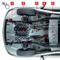
Figure: 1. Three-axle all-terrain vehicle on low pressure pneumatics designed by G. Vidyakin:
1 - front axle support, 2 - bumper, 3 - steering gear, 4 - rear wheel balancer, 5 - chain drive to the rear wheel, 6 - fuel tank, 7 - footboard, 8 - wheel disc, 9 - wheel hub, 10 - front axle, 11 - chamber, 12 - valve, 13 - detachable rim, 14 - rear axle wheel shaft.

Figure: 2. Steering gear and front axle support:
1 - front axle support, 2 - steering rod hinge, 3 - rack and pinion steering device, 4 - body floor, 5 - hinge, 6 - steering column, 7 - steering rod.
Wings, partitions, covers - plywood, connected to the body with duralumin corners, the floor - made of duralumin sheet, from below for rigidity duralumin corners are riveted. In the front part of the body, under the trunk partition, a small transverse niche is made for the front axle. In the rear part of the body under the seat boxes and further to the engine compartment, on both sides, there are longitudinal niches for the rear wheel balancers. By the way, the rear wheels are as close as possible to each other, the front wheels are somewhat forward - the turning radius of the all-terrain vehicle depends on this distance.
Above the wings in the front of the body, a windshield and two side windows are obliquely installed. Under the fenders, between the rear wheels, gas tanks are mounted on both sides, the section of which has the shape of a trapezoid tapering downward. Above all the wheels in the horizontal parts of the wings, rectangular cutouts are made, covered with a rubberized fabric: when hitting an obstacle, this allows the wheels to rise above the level of the wings and not brake against them.
The engine and transmission units are mounted on a frame that is integral with the body. It consists of four side members made of 40X40 mm steel angles and cross members made of square steel tubes. Outside, along the sides, there are small brackets from a 40X40 mm corner for attaching the rear wheel balancers. Wherever possible, the flanges of the longitudinal side member corners are trimmed to reduce weight and holes are drilled into them.

Figure: 3. Transmission device:
1 - chain drive, 2 - balancer frame, 3 - trunnion, 4 - balancer support, 5 - bracket, 6 - board, 7 - main gear, 8 - elastic coupling, 9 - brake drum, 10 - ring gear of the differential lock chain , 11 - brake lever, 12 - intermediate shaft, 13 - wheel shaft.

Figure: 4. The body of the all-terrain vehicle:
1 - trunk, 2 - windshield, 3 - driver's seat, 4 - box, 5 - space for passengers and luggage, 6 - window covered with rubberized fabric, 7 - engine cover, 8 - mud flaps, 9 - side, 10 - side spars of the engine and transmission power frame, 11 - rear wheel balancer recess, 12 - front axle recess.

Figure: 5. Frame for engine and transmission:
1 - middle spars (angle 40X40 mm), 2 - cross members (square tube 40X40 mm), 3 - side spars (angle 40X40 mm), 4 - cross member (angle 30X30 mm), 5 - balance beam support bracket (angle 40X40 mm).


The engine from the SZD motorized carriage is mounted in the rear part of the body on intermediate supports, which, in turn, are attached to the side members through four damping rubber pads from the Moskvich engine. On the intermediate supports, a cross member is also installed with an intermediate sprocket connected by a vertical chain drive to the output sprocket of the engine. The shaft of the intermediate sprocket is connected to an angular bevel gear mounted on the cross member through an intermediate roller with elastic couplings (the elastic element is a disc made of a flat drive belt 10 mm thick). An asterisk is installed on the output shaft of the gearbox, connected by a chain drive to the input shaft of the main gear (from the stroller), fixed on two crossbars. The output shafts of the main gear are connected through elastic couplings (from the same drive belt) to intermediate shafts with sprockets, which transmit rotation to the wheels through a chain drive. The output shafts of the main gear, intermediate shafts and trunnions of the balancers are located coaxially, as shown in Figure 3. It also shows that the trunnions are fixed in bearings on bearings, while the bearings of the intermediate shafts are pressed into the trunks. The inner trunnion is hollow, through which an intermediate shaft passes. At the inner ends of the intermediate shafts, brake drums from the wheels of the Tulitsa scooter are mounted, on which gear rims are installed; through chain drives, they are connected to the rollers of the differential lock. The latter is a sliding splined sleeve connecting the rollers. The axles of all transmission mechanisms are located practically in the same plane. Tensioning of chain drives: transmissions - with spacers, gears to wheels - with pressure screws. All bearing assemblies are protected from dirt by seals from the Volga car or have protective washers.

Figure: 6. Location of engine and transmission:
1 - elastic coupling, 2 - middle spar, 3 - cross member, 4 - side spar, 5 - bulkhead, 6 - differential lock thrust, 7 - reverse gear engaging thrust, 8 - reverse gear, 9 - angular gear, 10 - partition, 11 - intermediate shaft, 12 - cross member for fastening the support of the intermediate shaft sprocket, 13 - gear selector rod, 14 - air filter, 15 - tailgate, 16 - generator, 17 - engine, 18 - left side, 19 - muffler, 20 - starter, 21 - battery, 22 - chain drive to the rear wheels, 23 - support of the rear wheel balancer, 24 - rear wheel balancer trunnions, 25 - brake drum, 26 - chain transmission, 27 - differential lock unit.


The front axle of the all-terrain vehicle is made of a steel pipe Ø 60X3 mm, reinforced in the middle by a welded plate made of the same pipe. Along the axis of symmetry of the bridge, a horizontal axis is welded in perpendicular to it, the ends of which are fixed in bearing supports installed in the niche of the front of the body. Racks with pivots and pivots from the Volga car are welded to the flattened ends of the pipes. Rubber bumpers installed along the edges of the niche limit axle swinging in the vertical plane.

Figure: 7. Kinematic diagram of the all-terrain vehicle. Latin letters indicate:
Z is the number of teeth of the sprockets, t is the pitch of the roller-sleeve chains, b is the width of the roller-sleeve chains.

Steering, as required by the rules of the traffic police, factory-made, from a motorized carriage. The crankcase with the rack is mounted under the floor of the body on a bracket, the steering wheel shaft is connected to the pinion shaft through a cardan joint, the second (upper) steering shaft support is a ball bearing fixed to the bracket. Since the steering wheel is located in the plane of symmetry of the body, the steering rod joints on the rack are displaced to one side and the rods differ significantly in length, this leads to the fact that the swinging of the cross member is accompanied by a noticeable leash of the near wheel.
The rear wheel balancers are symmetrical frames welded from two rectangular pipes 40X20 mm, connected by cross members from the same pipes. The central support of the balance bar rotates in trunnions - bushings welded to the plates fixed to the frame. Wheel shafts at the ends of the balancers are of a similar design. The balancer frame is slightly curved, the balancer trunnions are located on top, and the wheel shaft supports are located below, so the wheel axles are 180 mm below the balancer joints. The rigidity of the balancers is low, under load they are somewhat deformed, just like the engine and transmission frame, however, the presence of elastic couplings and the possibility of misalignment of chain drives compensate for this disadvantage.
The wheels of the all-terrain vehicle are made of a wide-profile tire tube 1120X450X380. The tubular rims, center disc and camera support cradles are made of aluminum alloy. The lodges are connected to the rims by welding, to the disc - by means of riveted corners. The lodges are split, so that the outer rim is detachable; it is bolted to the disc. The disc in the central part is reinforced with a riveted pad, bolted to the hub. The valves have been moved to the side surface, which allows the chambers to rotate on the rims. Driving and steer wheels are interchangeable.
In the design of the all-terrain vehicle, several nodes are used, which can be attributed to those that accidentally turned up under the arm. One of them is a bevel gear. It can be dispensed with by placing the motor in the longitudinal direction. When assembling the transmission and installing the engine, all fasteners were fabricated and fitted in place. At the same time, all possible measures were taken to reduce the dimensions and weight of standard units; for example, the protrusions of the main gear of the motorized carriage were cut off, a small-sized muffler for the engine was made.
Control systems. All-terrain vehicle control and alarm system completely copy the car ones. Control drives: throttle - cable, clutch and brakes - hydraulic, gear shifting, reverse gear - by rods and handles located on board the all-terrain vehicle to the right of the driver; the differential lock control handle is also mounted there (via rods). All hydraulic cylinders are from the front wheel brakes of the stroller.
The power supply system is somewhat different from that adopted on a motorized carriage: along the axis of the crankshaft and engine fan, an automobile alternator is installed on four legs, connected to the crankshaft by an elastic coupling.
To heat the windshield, warm air is supplied from the engine cylinder through the air intake and corrugated sleeve by two automobile fans - at the inlet and outlet.
O. ILYIN, engineer
Many residents of northern latitudes and places with poor traffic are engaged in the development and assembly of various equipment with increased traffic. Tracked all-terrain vehicles are no exception. There are many different options for creating such a technique. But the most problematic issue for ATV designers is the manufacture of tracks.
You can, of course, use their factory production, but having completely assembled an all-terrain vehicle with your own hands, you also want to have tracks of your own production. Today, there are several options for creating such propellers, which practically do not differ in their technical characteristics from the factory ones.
Simple track variant
The simplest version and snowmobiles, is made from a conventional roller-sleeve chain and a conveyor belt. Moreover, its production does not require any special equipment and tools. In this case, the work can be done almost in the middle of the living room.
In order for the conveyor belt to serve for a long time, it is necessary to sheathe its edges with fishing line with a distance between the stitches of about one centimeter. This activity is very similar to sewing a fabric with a seamstress. In any case, this stitching will prevent the ribbon from unraveling while driving. You can fasten the ends together in any suitable way. A piano hinge-like hinge may work for this, or simply sewn, but it is unlikely to last long.
The thickness of the conveyor belt depends on the power of the power unit. If an engine from a Soviet-made motorcycle is installed in an all-terrain vehicle, then a 0.8-1 cm thick tape used on conveyors in agriculture has proven itself excellent. To stiffen the track, it is necessary to attach a sleeve-roller chain to its inner part. This can be done using bolts or stiff steel wire. The main thing is that the chain fits snugly in the surface of the conveyor belt.
Tracks made in this way are distinguished by their long-term operation, although they are easy to manufacture. In addition, repairs can be easily carried out if necessary, even in the field.
Tire propellers
 Many owners and snowmobiles use ordinary tires from a car as tracks for their equipment. For these purposes, tires from trucks are needed, while it is worth choosing them with the required pattern so as not to complicate your work in the future.
To make a caterpillar drive from a tire, it is necessary to cut the sides from it, leaving only the part with the tread. This event takes a lot of effort and requires patience, since only a well-sharpened boot knife is needed for work.
In order to slightly simplify the manufacture, it is necessary to periodically wet the knife with soapy water, which will facilitate the process of cutting the rubber. Some people use specially designed devices for these purposes. You can also use an electric jigsaw with a fine-toothed file attached to it. It also needs to be watered with soapy water.
The first step is to cut the beads from the tire. Further, if necessary, it is required to remove several inner layers in the resulting caterpillar. This is done to make it soft. If the tread pattern does not suit you, then you should start cutting a new one, which is quite a painstaking task.
This type of tracked lug has one distinct advantage over the previous version. Since it is solid, without connections, its reliability is much higher. Of the negative points, a small track width can be noted, but to increase it, two or three tires can be spliced.
Belt tracks
 The simplicity of the manufacture of such tracked propellers is increasingly attracting the owners of all-terrain vehicles to use them on their equipment. Belts with a wedge-shaped profile are assembled into a single structure using lugs, which are riveted to the belts or screws.
As a result, it turns out that the track blade already has holes for the sprocket. To do this, the belts must be stacked at close intervals.
Making a caterpillar for an all-terrain vehicle
An all-terrain vehicle is understood as a vehicle with an all-terrain vehicle. These include tractors, snowmobiles, SUVs and tanks. Since it is often from improvised vehicles. Conceptionally, motorcycles or motor scooters are used for this, but the end result is a vehicle that is not afraid of either off-road or dirt. The increased cross-country ability of an all-terrain vehicle mainly depends on its tracked propellers, which are put on the wheels.
In this version, the caterpillar will have four stripes 5 centimeters wide. They need to be cut from a conventional conveyor belt. Then make the connection with the lateral sides using a profile in the shape of the letter P. Next, you need to make the balancers. Using a stamp, you need to make parts into the floor of the wheel from sheet steel. After that, it is necessary to make the hubs from bronze. The half wheels should be connected with six bolts. The balancers are made.
 The next step will be the production of shafts for the track support drums. Holes for bearings should be made in them. The drums can be made from duralumin blanks. Connecting them together, you must insert a rubber sprocket. It turns out that the caterpillar is driven by a drive sprocket with a chain drive. It is installed on the rear fork.
After that, you should collect the entire caterpillar into a single whole.
The vertical bow must be fitted with a steel bushing through which the wheel axle passes. A mechanism is attached to the lug on this bushing that secures the rear fork structure. Tracked balancers are attached to the remaining ears of the all-terrain vehicle. The propulsion unit is ready for use.
As you can see, you can make a caterpillar in different ways, the main thing is to have patience and desire.