A selection of amateur radio designs of various types of circuit breakers and lighting control schemes for lighting both indoors and outdoors.
When lighting long corridors, stairwells, porches, hangars and similar places where it is required to turn on or off the light from two or more places, usually use corridor switches. Install them in opposite parts of the corridor. The circuit is standard and is probably known to any electrician, and to change the state of such a switch, the switch must be flipped to the opposite of the previous position. Therefore, a typical circuit requires three wires to be routed to the switches instead of two, and this is only if the lighting needs to be controlled from two places. Within the framework of this article, we will show illustrative examples of how you can get around such disadvantages.
Such schemes are ideal for use in places where the presence of a person is not long-term. The light burns just as long as you need it. After leaving the place, the lighting is turned off with a short time delay, which allows you to save a lot of electricity. In addition, such radio amateur designs are an excellent way to scare off petty thieves who are frightened by the suddenly turned on light.

The most common design is a light control based on a motion sensor and an AVR microcontroller, but if a person is just standing, then the lighting will turn off. The circuit based on the pyrodetector is rather complicated and needs adjustment and adjustment. But the circuit on the ultrasonic sensor is devoid of these drawbacks.
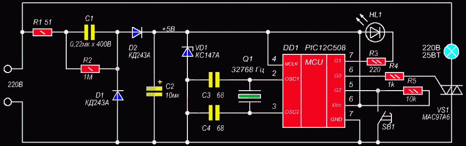
The automatic light switch is able to turn on or off the light or other load at a programmed time every day. It is assembled using a PIC12C508 microcontroller. (The firmware is attached to the MK).
Getting into the dark, it is not always possible to immediately find the light switch, especially if it is far from the door. A similar situation can be, in the case of leaving the room, when we turned off the lighting and then have to go to the exit by touch. An acoustic switch of the circuit and design of which are discussed in this article can save you from problems.
The clap switch device is triggered by a clap sound. If the volume is sufficient, then the circuit turns on the lighting in the entrance (or other room) for one minute. The first design has one interesting feature to prevent looping of work, namely, the microphone turns off automatically after turning on the lighting, and turns back on only a couple of seconds after turning off the light.
There is a circuit breaker at its core; the domestic microcircuit KR512PS10 is put, which is a multifunctional multivibrator - counter. The microcircuit includes logic inverters for an RC circuit or a quartz multivibrator and a counter with a maximum division ratio of 235929600. That is, when using a standard 32768 Hz clock resonator and selecting the maximum division ratio mode, the counter will output pulses with a period of 120 minutes. And the unit appears at the exit after 60 minutes. Thus, if you set the moment when the unit appears at the output after zeroing, then a time interval of one hour is obtained. The outputs of the microcircuit 10 and 9 are made with open drains, so pull-up resistors are needed there. Well, now I'll tell you a little about the other pins of the microcircuit and their purpose (it can be useful when upgrading or modifying the circuit for another purpose). And so, pin 3, this is the STOP pin, when a logical unit is applied to it, the counter freezes. Conclusion 2 - zeroing, feed one to it and the counter is reset. Pin 11 adjusts the level at pin 10. If pin 11 is zero, the level at pin 10 will be the opposite of the level at pin 9.
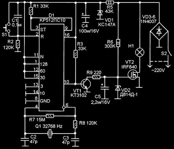
Circuit breaker circuit for KR512PS10
If there is one, then pins 10 and 9 work the same way. To set the division ratio, use pins 1, 12, 15, 13, 14. If all of them have zeros, then the division ratio will be the minimum basic, equal to 1024. When a unit is applied to any of these setting pins, the base factor is multiplied by the factor of this output. For example, if you feed one to pin 1 (128), then the division factor will be 128x1024 = 131072. A unit can be applied only to one of the pins 13, 14 or 15, while the other two of this three pins must be zeros. But on conclusions 1 and 12, units can be supplied at the same time. All division factors, on the conclusions of which the units are supplied, are multiplied, and then the obtained result is multiplied by the base factor of 1024. Turning on the night light can be done in two ways. Initially, the night light is turned on as usual with the S2 mains switch. In this case, the lamp immediately lights up and the timing begins. If it has already been turned on and off before, then you can turn it on again either by pressing the S1 button, or by turning it off and then turning it on with the S2 switch. After any of the above options for switching on, the D1 counter turns out to be zero (capacitor C1 or button S1). In this state, the outputs of the counter (pins 9 and 10) are zeros. Transistor VT1 is closed and does not bypass the gate circuit of the field-effect transistor VT2. An opening voltage is supplied to the gate VT2 through the resistor R6, which is limited to an acceptable level by the Zener diode VD2.
Therefore, the transistor VT2 opens and turns on the H1 lamp (which is powered by a pulsating voltage through the VD3-VD6 rectifier bridge. full opening, according to the reference data, must be at least 8V, therefore, the gate VT2 and the microcircuit are powered from different sources, and the transistor VT1 performs the functions not only of an inverter, but also of a level matcher. Pin 9 stops the counter by feeding a logical unit to pin 11. And pin 10 opens the transistor VT1. That, opening, shunts the gate circuit of the field-effect transistor VT2 and the voltage at its gate drops to 0. Transistor VT2 closes and the lamp H1 goes out. The microcircuit is powered by voltage 5V (or rather 4.7V) from parametric stabilization an isolator on a zener diode VD1 and a resistor R5. The S1 button must be momentary. You can do without this button at all.
In this case, in order to turn on the night light after it has been automatically turned off, you will need to turn it off with the S2 power switch and turn it on again. By the way, you can also abandon the power switch in favor of the S1 button. But then it will be possible to turn off the night light ahead of time only by disconnecting the plug from the mains socket. And there is also a third option - installation instead of a switch button. Then the switch, being in the on state, will block the timer, and there will be no automatic switching off of the light. And to switch to automatic mode, you will need to turn off the switch installed instead of S1. Quartz resonator Q1 is a standard clock resonator. It can be replaced with an imported 16384 Hz clock resonator (from Chinese quartz alarms), but then the time that the night light is on will double, respectively.
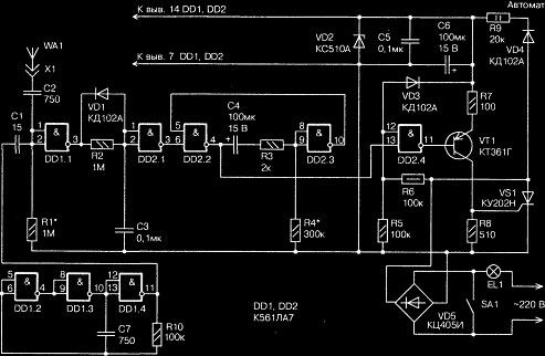
In the absence of the necessary quartz resonator, as well as, if you want to make a continuously adjustable time interval, you can perform the multivibrator part of the circuit on RC elements with a variable resistor, as shown in the second figure. The IRF840 transistor can be replaced with a domestic analogue of the KP707B, KP707V type. The KT3102 transistor is practically any ordinary low-power transistor of the p-p-p structure, for example, KT315. The KS147A zener diode can be replaced with any 4.7 - 5.1V zener diode. There is a large selection of imported zener diodes for this voltage. The same can be said about the D814D-1 zener diode, but only it should be for any voltage in the range from 9 to 13V. The rectifier bridge is made on 1N4007 diodes, which is now, perhaps, the most common medium-power rectifiers operating on the mains voltage. Of course, it can be replaced with any other rectifier diodes with parameters for forward current and reverse voltage no less than this. Capacitor C4 must be at least 6V, and capacitor C5 at least 12V. Low-power lamps are usually installed in nightlights. If this is an incandescent lamp, then its power does not exceed 25-40 W. However, this circuit allows operation with lamps with a power of up to 200W inclusive (without a radiator for VT2). Although, this may already matter only if this scheme will not be used to control a night light.
The circuits discussed in this article are designed to automatically turn on street lighting at nightfall and automatically turn off at dawn. Some of them have original circuit solutions.
The proposed amateur radio design smoothly turns on and off the staircase lighting when a person appears in the area of the pyroelectric motion sensor (DD), and thanks to the K145AP2 microassembly, it is precisely the smooth increase in brightness when the light is turned on and its decrease when turned off.
The circuit breaker consists of a light sensor, a converted Chinese quartz alarm clock, and a trigger combining them with a high-voltage key at the output. The phototransistor FT1 is used as a light sensor. By selecting the resistance of the resistor R1, its sensitivity is adjusted so that during the day the voltage on R1 is above the switching threshold of the logic element to one, and at night below this threshold. If the sensor is configured correctly, then the voltage at pin 1 of D1.1 is still light enough - a logical unit. With darkening, the phototransistor closes and the voltage at pin 1 of D1.1 decreases. At some point, it reaches the upper threshold of a logical zero. This causes the start of the one-shot D1.1-D1.2, which generates a pulse that sets the flip-flop D1.3-D1.4 to one.
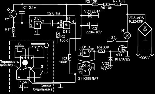
Circuit breaker circuit from the alarm clock
The voltage from the output of the element D1.3 is fed to the gate of the high-voltage field-effect transistor VT1. Its channel opens and turns on the lamp of the lamp. The gate VT1 is connected to the output D1.3 through the resistor R4, which reduces the load on the output of the logic element from the charge of the relatively large capacity of the gate of the transistor. The presence of the R4-VD2 circuit greatly facilitates the operation of the logic microcircuit and eliminates the tendency to fail. The lamp is on. The trigger is in a steady state, so it stays on even if the light from the lamp hits the phototransistor. A Chinese quartz alarm mechanism is used to turn off the lamp. The alarm clock must be set for real time, and the bell at the time when the lamp must be turned off, for example, for two hours. The alarm clock is being redesigned. The diagram shows the alarm clock circuit, it shows the electronic alarm clock device board with all connections. The board is shown as it looks. B is the alarm clock buzzer, L is its stepping electric drive, S is the switch associated with the clockwork. The battery is also indicated. To give a command to turn off the lamp, a mechanical switch S, associated with the alarm mechanism, is used. To disconnect it from the alarm microcircuit, you need to cut the printed track on the board. And then solder the wire to the printed circuit board connected to the switch S. All these operations can be done without removing the board from the alarm clock. Carefully remove the back cover of the clockwork, after removing all the handles.
You need to act carefully so that the mechanism does not crumble. Then, with a thin awl, we tear the printed track on the board and solder the mounting wire with a thin soldering iron. After that, we bring the wire into the battery compartment and very carefully close the lid so that all the gears are in their holes. As soon as the alarm clock hands are set at the specified time, for example, at 2-00, the S contacts close and close pin 13 D1.4 to a common minus.
This is equivalent to applying a logical zero to this pin. The flip-flop switches to zero, the voltage at the D1.3 output drops, and VT1 closes, turning off the H1 lamp. The alarm clock has a standard 12-hour scale, so the contacts will close twice a day, but this is not significant, since, for example, closing them at 2:00 p.m. will not lead to anything, because the light is off during the day. Although, an incorrect installation option is also possible, for example, at 7-00, that is, if you want the light to burn all night and turn off at dawn, at 7-00 in the morning. But, if it gets dark at 18-00 (6-00 in the evening), then the light will turn off at 19-00 (7-00 in the morning). Therefore, such a setting should be avoided - it is necessary that the setting of the alarm clock corresponds to the day and night time of the day, and not morning and evening. The circuit and the lamp are powered by a constant pulsating current through a rectifier on diodes VD3-VD6. The voltage is supplied to the microcircuit from a parametric stabilizer on resistors R5-R7 and a Zener diode VD1.
Switch S2 is used to manually turn on the lamp. As a photosensor, you can use a phototransistor, photoresistor, photodiode connected by a photoresistor (reverse polarity). The brand of the used phototransistor is not known to me. I took a phototransistor from disassembling the tape drive mechanism of an old faulty VCR. I experimentally checked where the output is and what the resistance R1 needs is about 70 kOhm (set 68 kOhm). If you use another phototransistor, photoresistor or photodiode, you will need to carry out the same experiments in order to select the required resistance R1. Previously, you can replace R1 with two variable resistors of 1 megohm and 10 kOhm, connecting them in series.
Experimenting with light, find the required resistance, then measure and replace with a constant resistor close to the nominal value. Without a radiator and with the diodes shown in the diagram, the KP707V2 transistor can switch a lamp with a power of up to 150 W inclusive. Diodes KD243ZH can be replaced with KD243G-E, 1 N4004-1 N4007 or others similar. Chip K561LA7 can be replaced with K176LA7 or CD4011. Zener diode VD2 - any voltage 12V, for example, KS512. Transistor KP707V2 can be replaced with KP707A1, KP707B2 or IRF840. The quartz alarm clock is "KANSAI QUARZ", or so it is written on its dial.
Many people forget to turn off the light in the toilet, bathroom or hallway when leaving the room. And if they do not forget, then the switch in these places can quickly break down from frequent mechanical stress. All this indirectly suggests the need to install an automatic lighting control unit, for example, such radio amateur developments, which are described in this article. The proposed block diagrams automatically control the lighting, and the control in them is the door in the reed sensor system.
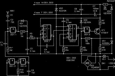
The circuit breaker is assembled on only two digital microcircuits DD1 and DD2, one transistor; and one SCR. It contains a pulse generator built on logic gates DD1.2-DD1.4, capacitor C7 and resistor R10, and produces rectangular pulses with a frequency of 10,000 Hz (or 10 kHz is the audio frequency). Moreover, the stability of the frequency does not really matter. Therefore, the repetition period of these pulses is 0.1 ms (100 μs). These pulses are practically symmetrical, so the duration of each pulse (or the pause between them) is approximately 50 μs.
On the logical elements DD1.1, DD2.1, capacitors C1-C3, resistors R1, R2, diode VD1 and antenna WA1 with connector X1, a capacitive relay is made, which responds to the capacitance between the antenna and the network wires. When this capacitance is insignificant (less than 15 pF), rectangular pulses of the same frequency of 10 kHz are formed at the output of the DD1.1 element, but the pause between which is reduced (due to the C1R1 differentiating chain) to 0.01 ms (10 μs). It is clear that the pulse duration is 100 - 10 = 90 μs. However, in such a short time, the capacitor C3 still manages to discharge almost completely (through the VD1 diode), since its charging time (through the resistor R2) is long and is approximately equal to 70 ms (70,000 μs).
Circuit breaker luminaire circuit
Since the capacitor is charged only at a time when there is a high voltage level at the output of element DD1.1 (be it a pulse or just a constant level), during a pulse of 90 μs duration, the capacitor C3 does not have time to charge any noticeably, but; therefore, at the output of the element DD2.1, a high voltage level remains all the time. When the capacitance between the antenna WА1 and the network wires increases (for example, due to the human body) to 15 pF or more, the amplitude of the pulse signal at the inputs of the DD1.1 element will decrease so much that the pulses at the output of this element will disappear and turn into a constant high level. Now the capacitor C3 can be charged through the resistor R2, and a low level is set at the output of the element DD2.1.
It is he who launches a one-shot (waiting multivibrator), assembled on logic elements DD2.2, DD2.3, capacitor C4 and resistors R3, R4. While the capacitance of the antenna circuit is small, due to which a high voltage level is present at the output of the DD2.1 element, the one-shot is in a state in which the output of the DD2.2 element will be low, and at the output of DD2.3 - high. The timing capacitor C4 is discharged (through the resistor R3 and the input circuit of the element DD2.3). However, as soon as the capacitance increases significantly and a low level appears at the output of the DD2.1 element, the one-shot will immediately form a time delay, at the indicated ratings of the C4R3R4 circuit, equal to approximately 20 s.
Just at this time, a low level will appear at the output of the DD2.3 element, and a high level at the output of DD2.2. The latter is able to open an electronic key made on a logical element DD2.4, a transistor VT1, a diode VD3 and resistors R5-R8. But this key does not remain open all the time, which would be clearly inappropriate both in terms of energy consumption and, most importantly, because of the completely useless heating of the control junction of the VS1 trinistor. Therefore, the electronic key works only at the beginning of each half-cycle of the network, when the voltage across the resistor R5 increases once again to about 5 V.
At this point in time, instead of a high voltage level, a low voltage appears at the output of the DD2.4 element, due to which first the transistor VT1 opens, and then the trinistor VS1. But, as soon as the latter opens, the voltage on it will significantly decrease, which will decrease the voltage at the upper (according to the diagram) input of the DD2.4 element, and therefore the low level at the output of this element will again abruptly change to high, which will cause automatic closing of the transistor VT1 ... But the trinistor VS1 during this half-period will remain open (on).
During the next half-period, everything will repeat in the same sequence. Thus, the electronic key opens only for a few microseconds required to turn on the VS1 SCR, and then closes again. Due to this, not only energy consumption and heating of the SCR are reduced, but also the level of radiated radio interference is sharply reduced. When the 20-second exposure ends, and the person has already left the "magic" rug, a high level reappears at the output of the DD2.3 element, and a low level at the output of DD2.2. The latter locks the electronic key at the bottom input of the DD2.4 element. In this case, the transistor VT1, and therefore the trinistor VS1, can no longer be opened (according to the upper input of the DD2.4 element in the diagram) by synchronizing network pulses. If the exposure has expired, but the person still remains on the mat (on the WA1 antenna), the electronic key will not be locked until the person leaves the mat.
As can be seen from Fig. 1, the VS1 SCR is able to close the horizontal (according to the circuit) diagonal of the VD5 diode bridge. But this is tantamount to closing the vertical diagonal of the same bridge. Therefore, when the VS1 trinistor is open, the EL1 lamp is on; when it is not open, the lamp is extinguished. The EL1 lamp and the SA1 switch are standard electrical appliances available in the hallway. So, with the SA1 switch, you can still turn on the EL1 lamp at any time, and regardless of the machine. You can turn it off only when the VS1 trinistor is closed. However, it is also important that after the contacts of the SA1 switch are closed, the circuit breaker will be de-energized. Therefore, the formation of the time delay can always be interrupted at will by closing and then opening the SA1 switch. The machine is powered by a parametric stabilizer containing a ballast resistor R9, a rectifier diode VD4 and a Zener diode VD2. This stabilizer produces a constant voltage of about 10 V, which is filtered by capacitors C6 and C5, and capacitor C6 smooths out the low-frequency ripples of this voltage, and C5 - high-frequency ones.
Let us briefly consider the operation of the machine (assuming that the SA1 switch is open). Until the antenna WA1 is blocked by the capacitance of the human body, a constant high level is present at the output of element DD2.1. Therefore, the one-shot is in standby mode, when at the output of the DD2.2 element there is a low level, which locks (at the lower input of DD2.4 element) the electronic key. As a result, the VS1 SCR does not open with the sync pulses arriving at the upper input of the DD2.4 element from the VD5 bridge through the R6 resistor. When a person blocks the antenna circuit, a low level appears at the output of the DD2.1 element, which triggers the one-shot, and a high level appears at the output of the DD2.2 element, which opens the electronic key and the VS1 SCR for 20 seconds (the EL1 lamp is on during this time). If by that time the blocking of the antenna circuit is terminated (the person has left the mat), the EL1 lamp goes out, if not, it continues to burn until the person leaves the mat.
In any case, the one-shot (and the machine as a whole) switches back to standby mode. To turn off the light ahead of schedule (without waiting for 20 s), if it is suddenly necessary, it is enough to close and open the SA1 switch. Then the machine also goes into standby mode. The required sensitivity of the machine depends on the size of the WA1 antenna, the thickness of the mat and other factors that are difficult to account for. Therefore, the desired sensitivity is selected by changing the resistance of the resistor R1. So, an increase in its resistance leads to an increase in sensitivity, and vice versa. However, one should not get carried away with excessive sensitivity for two reasons. First, an increase in the resistance of the resistor R1 over 1 MΩ, as a rule, requires filling it with varnish in order to exclude the influence of air humidity on the operating mode.
Secondly, with excessive sensitivity of the machine, its false alarms are not excluded. They are also possible after the floor in the hallway has been washed, but not yet dry. Then, to turn off the light, you should temporarily disconnect the WA1 antenna using a single-pole connector X1. Antenna WA1 is a sheet of one-sided foil glass-textolite, covered from the side of the foil with a second sheet of thin textolite, getinax or polystyrene. Along the perimeter of the first sheet, the foil is removed in one way or another to a width of about 1 cm.Then both sheets are glued together, carefully filling with glue (for example, with epoxy putty) those peripheral places of the antenna where the foil is removed.
Particular attention should be paid to the reliability of the termination of the wire going from the foil to the outside of the antenna. The dimensions of the antenna depend on the mat available. Approximately its area (by foil) is 500 ... 1000 cm2 (assume 20x30 cm). If the length of the wire going from the machine to the antenna is significant, it may need to be shielded (the screen stocking is connected then, on the one hand, the sensitivity of the machine will inevitably decrease, on the other hand, the capacitance of the C1 capacitor may have to be slightly increased. network, on top it must be covered with good and thick insulation. The machine itself is assembled on a plastic board by printed or hinged mounting. The board is placed in a plastic box of a suitable size that prevents unintentional touching any electrical point, since they are all in one or another degrees are dangerous, since they are connected with the network. For this reason, all the soldering during the establishment should be carried out after disconnecting the machine from the network (from the switch SА1). The setting consists in choosing the sensitivity (resistor R1), as already mentioned, and the exposure time of the one-shot (resistor R4), if necessary.By the way, the shutter speed can be increased to 1 min (at R4 = 820 kO m) and more.
The highest power of the EL1 lamp (or several lamps connected in parallel) can reach 130 W, which is quite enough for a hallway. Instead of a trinistor KU202N (VS1), it is permissible to install KU202M or, in extreme cases, KU202K, KU202L, KU201K or KU201L. Diode bridge (VD5) of the KTs402 or KTs405 series with the letter index Zh or I. If we use the bridge of the same series, but with the index A, B or C, the permissible power will be 220 W. This bridge is easy to assemble from four separate diodes or two assemblies of the KD205 series. So, when using diodes KD105B, KD105V, KD105G, D226B, KD205E, the lamp power will have to be limited to 65 W, KD209V, KD205A, KD205B - 110 W, KD209A, KD209B - 155 W, KD225V, KD225D202 - 375 W , KD202M, KD202N, KD202R, KD202S - 440 W. Neither the SCR nor the diodes of the bridge need a heat sink (radiator). Diode VD1 - any pulse or high-frequency (germanium or silicon), and diodes VD3, VD4 - any rectifier, for example, series KD102-KD105. Zener diode VD2 - for a stabilization voltage of 9 ... 1O V, for example, series KS191, KS196, KS210, KS211, D818 or type D814V, D814G. Transistor VT1 - any of the series KT361, KT345, KT208, KT209, KT3107, GT321. Chips K561LA7 (DD1 and DD2) can be easily replaced with KM1561LA7, 564LA7 or K176LA7.
To improve heat dissipation, a two-watt ballast resistor (R9) should be composed of four half-watt ones: 82 kΩ resistance in parallel connection or 5.1 kΩ resistance in series connection. The rest of the resistors are of MLT-0.125, OMLT-0.125 or VS-0.125 type. For electrical safety, the rated voltage of the capacitor C2 (best of all mica) should be at least 500 V. Capacitors C1-C3, C5 and C7 are ceramic, mica or metal-paper with any rated voltage (except for C2). Oxide (electrolytic) capacitors C4 and C6 of any type with a rated voltage of at least 15 V.
Circuit breaker circuit diagram
Automatic switch; is an electronic analogue of a conventional push-button switch with latching, which is triggered every time: one press - the lamp is on, the other - the lamp is off. This machine is also built on only two digital microcircuits, but instead of the second K561LA7 microcircuit (four 2I-NOT logic gates), it uses the K561TM2 microcircuit (two D-flip-flops). It is easy to see that the triggers of the last microcircuit are installed instead of the one-shot of the previous machine. Let's briefly consider their work in the machine. The purpose of the DD2.1 trigger is auxiliary: it provides a strictly rectangular shape of the pulses supplied to the counting input C of the DD2.2 trigger.
If there were no such a pulse shaper, the DD2.2 trigger would not be able to switch clearly at input C into a single (when its direct output is high, and at its inverse - low) or zero (when the output signals are opposite to those indicated) state. Since the setting input S (setting "one") of the flip-flop DD2.1 is constantly applied to a high level relative to its setting input R (setting "zero"), its inverse output is a conventional repeater.
That is why the integrating circuit R3C4 sharply sharpens the fronts of the pulses taken from the capacitor C3. When the voltage across it is low (the antenna WA1 is not influenced by the hand), the inverse output of the DD2.1 trigger is also at a low voltage level. But as soon as the voltage on the capacitor C3 rises (bring your hand close enough to the WA1 antenna) to about 5 V, the low level at the inverse output of the DD2.1 trigger will suddenly change to a high one. On the contrary, after reducing the voltage across the capacitor C3 (the hand was removed) below 5 V, the high level at the same inverted output will also abruptly change to a low one.
However, only the first (positive) of these two surges is important for us, since the DD2.2 trigger does not react to a negative voltage surge (at input C). Therefore, the DD2.2 trigger will switch to a new state (single or zero) whenever the hand is brought to the WA1 antenna at a sufficiently close distance. The direct output of the DD2.2 trigger is connected to the upper (according to the scheme) input of the DD1.2 element, which is part of the electronic key. Acting on this input, the trigger is able to both open and close the electronic key, and with it the VS1 trinistor, thus turning on or off the EL1 lamp.
Note that the direct connection of the inverse output of the DD2.2 trigger with its own information input D ensures its operation in the desired counting mode - "every other time", but the integrating circuit C5R4 is needed so that after the shutdown of "traffic jams") trigger DD2.2 would be necessarily set to zero, corresponding to the extinguished lamp EL1. As in the previous machine, the EL1 lamp can also be turned on with a conventional SA1 switch. But it will be turned off if, on the one hand, the SA1 switch is open, on the other, the DD2.2 trigger is set to zero.
Another feature of this machine is that the pulse generator (10 kHz) is assembled according to a simplified scheme - only on two elements (DD1.З and DD1.4) instead of three. Instead of the K561TM2 (DD2) microcircuit, it is permissible to use KM1561TM2, 564TM2 or K176TM2. Other details in it are the same as in the previous one. It makes sense to reduce the size of the antenna to 50 ... 100 cm2 in the area of the foil
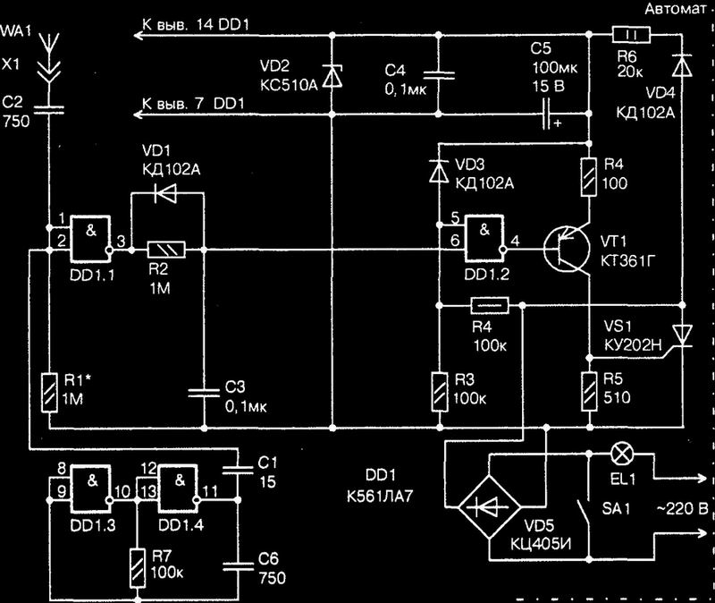
Circuit breaker simple circuit
This device is, as it were, an electronic analogue of a conventional self-resetting button: pressed - the lamp is on, released - it goes out. It is very convenient to equip such a non-contact "button", for example, a soft chair, the light above which automatically lights up whenever you sit in it for reading, knitting or other active recreation. The difference between this simplified automaton from the previous ones is that it does not have either a one-shot or triggers. Therefore, the capacitor C3 is directly connected to the lower (according to the diagram) input of the element DD1.2 of the electronic key. If there is no “rider”, the WA1 antenna hidden under the seat trim does not prevent the appearance of a pulse signal at the output of the DD1.1 element, the capacitor C3 is discharged, and therefore the electronic key and the VS1 trinistor are closed, the EL1 lamp does not light up. When the resting person sits down in the chair, the indicated pulses disappear, the capacitor C3 is charged and the electronic key allows the opening of the VS1 trinistor, the light is on. Of course, these examples do not exhaust all the possibilities of using light automata.