The instrument panel was stock Vladimirskaya, slightly improved ... namely 1. uniform diode illumination, 2. PWM brightness control, 3. Smooth switching on and off the backlight when the engine starts 4. All possible indicator lamps are connected.
I absolutely did not like the tidy of 31105, I found it in Moscow tidy from 3111, manufactured by RAR (Riga).
The price was even cheaper than the new one from 31105
Studied the material:
www.drive2.ru/cars/gaz/31… rnal / 4035225266124025366 /
www.drive2.ru/cars/gaz/31 ... / 288230376152422866 / # post
www.drive2.ru/cars/gaz/31 ... / 288230376152404924 / # post
www.drive2.ru/cars/gaz/24 ... / 288230376152246368 / # post
Stage 1
In addition to tidy for installation you need to buy 2 connectors. They fit from: Skoda Octavia, Golf 4, Passat B5, Audi A6 ...

specifically mine - from Skoda Octavia.
Then, having disassembled the pads, you need to add the missing wires to the terminals (the terminals are all in the block, but without wires).
After the wires are inserted, we try the tidy for performance

Stage 2
All tables and diagrams that are on the Internet, following the links above, fit me ... but everywhere there are errors ... both in polarity and in purpose. Therefore, I made my own table purely "for internal use" and I advise you to do it in a MANDATORY manner.
By specifying just a few graphs:
1. What block
2. Purpose of the wire
3. The color of the wire in the block (they are the same ones)
4. Signal polarity
5. Color in car wiring

table in progress
When everything is connected, we get something like this


Stage 3
Installing a tidy on a torpedo.
I chose the method indicated by the first link at the beginning of the article, it took a lot of time.

left mount

right mount


Installed

Installed

backlight

from afar
At first I wanted to install additional. illumination as in its old tidy… but as it turned out, the backlight of the PP 3111 is quite enough in the evening and at night… it is uniform!
From the problems identified after installation:
1. Almost all signaling devices on PCB are designed for mass supply! therefore, for such indicators as - open doors, heated mirrors and rear stele, and I don't remember what else ... I need to purchase a relay converter from + to - ... I only found this just to open the doors.
2. The temperature indicator does not show correctly!
On 3111 there is no temperature sensor for the tidy on the thermostat ... apparently they are paired with MIKAS there ... the treatment of this bug is at the stage of thinking ... how I decide that I will unsubscribe here.
3. Tidy is able to show the outboard temperature ... but I never found which sensor to connect to it.
The Gazelle is a very popular truck in Russia. On the basis of GAZ-3302, a lot of other vehicles are also produced. These are both public transport and passenger minibuses. What do all these models have in common? They are united not only by a common frame structure, but also by a single instrument panel. "Gazelles" of different years of production were equipped with different dashboards. Well, let's look at exactly what and what are the features of each shield.
Appointment
The function of any "tidy" is informational. This also applies to the Gazelle Business instrument panel. In a small area in the torpedo there are all the necessary indicators, bulbs and scales. Usually the shield is located behind the wheel, in front of the driver's eyes. But there are also exceptions. For example, in UAZ "Hunter" the panel is located in the center. But we will not consider the assembly of this car yet. Let's go back to our Gazelles. Externally, their panels are three to five round dials with several signaling sensors. In any dashboard, the main dials are:
- Speedometer.
- Tachometer.
They are the largest and centered. In addition, there are a lot of auxiliary elements on the instrument panel ("Gazelle" of the old model and the new one). These scales inform the driver about:
- The current temperature of the engine (namely, the coolant in the engine jacket).
- Oil pressure in the system.
- Fuel level in the tank.
- The voltage in the on-board network.
If we consider more modern devices, information about the current time will also be displayed here.
Where is it installed?
Note that the Gazelle instrument panel can be found on other cars. These are Sobol and Volga. The device has the same wiring diagram. Outwardly, these shields look identical.
Types
There are several types of these panels:
- The old model "Euro-1". Installed on cars from 1994 to 2002 inclusive.
- The old model "Euro-2". These shields can be found on Gazelles with a new "muzzle" (with drop-shaped headlights).
- New sample. They are installed to this day on "Next", starting with "Gazelle Business".
Below we will consider the features of each Gazelle instrument panel.
Panel "Euro-1"
This tidy was installed on both "Sable" and "Gazelle" of all modifications. What design it has, the reader can see in the photo below.
This dashboard remotely resembles the "Zhiguli" -seven panel. But still, this is an original development. There are no electronic pointers here. Only available:
- Speedometer.
- Tachometer.
- Oil pressure (not level) sensor.
- Indicator of voltage in the network.
- fuel and antifreeze temperature.
In this form, the shield was produced for about eight years. No changes were made during this period.
Panel "Euro-2"
This device is also called "Riga". It was also installed on the Volga, in particular the 31105 series. This shield has a slightly different design and appearance. It was developed specifically for the new torpedo, with a rounded visor. No new sensors have appeared here, but the location of some of the dials has changed.

The speedometer scale has now become larger in diameter, and the antifreeze temperature and oil pressure sensors are combined into one "well". The odometer was also changed. If earlier the main odometer was designed for a mileage of up to one hundred thousand (after which it was reset to zero), now its boundary line is one million kilometers. Of course, few people have met a Gazelle with a similar mileage, but nevertheless, the addition of one number greatly facilitated some work and maintenance (no need to guess and think about when to replace the chain, and even overhaul the engine). As the owners say, the new Riga Gazelle instrument panel is much more convenient to operate. Also, the needle of the tachometer and speedometer does not "walk" here. Since 2003, these scales have been powered by an electrician, not a cable. The readings have become more accurate.
"Euro-3"
For the first time such a device appeared on the Gazelle Business cars. The old-style Gazelle instrument panel went out of fashion, and all Gazelle owners began to install the updated panel in their car. The owners of the Volga were engaged in the same alterations. Indeed, the new dashboard has become much more informative, convenient and practical. But what can I say, his design is much more modern. As the reviews say, with it, the interior looks fresher and not so dull. The reader can see how the updated gadget looks like in the photo below.

But it should be noted that this shield has slight design differences. So, on some models, the instrument scales had a darker shade. But this did not affect the information content in any way - the reviews say. Another feature of the new dashboard is the presence of sound indication. The driver can now hear a distinctive signal if:
- The fuel level has dropped to the minimum mark.
- The engine temperature has increased to 105 degrees Celsius or more.
- The handbrake has not been released. Remarkably, the signal is triggered only when the car starts moving at a speed of 2 or more kilometers per hour.
The new tidy has received large modern dials. Now the scales of the speedometer and tachometer are in opposite places (in comparison with the "Rizhskaya"), and their diameter has become the same. On the left is the fuel gauge and on the right is the coolant temperature gauge. But where did the mains voltage and oil pressure indication go? The answer is simple - this data is in the on-board computer. It is located in the "well" of the tachometer. By default, only the time is shown here. But if you click on the button on the right, you can switch the mode. So, the driver can find out the data from the voltmeter and the oil pressure in real time.
What is noteworthy, when the oil falls below 0.2 bar, a flashing window with a sensor will light up.
A digital odometer is provided on the left side. The top shows the total, and the bottom shows the daily mileage. It is reset to zero by pressing the key on the left. Also on the panel of the new sample there are 20 indicators (including ABS and EBD) that light up in the event of a malfunction of a particular system.
Principle of operation
The algorithm of action for all panels is the same. Each light bulb and arrow interact with a specific element. So, the readings of both the speed and the mileage come from the sensor that is screwed onto the box. The engine information comes from the crankshaft sensor. And the voltage data comes from the generator terminals. What is noteworthy: if you do not connect the voltage contact, the machine will not take charge even with a working generator. This problem is accompanied by a red battery light on the panel. If it is on, then there is an open circuit and the wire does not fit on the tidy connector contact. As for the oil pressure and, this information comes through the terminals from the corresponding sensors.
Problems
Are there any problems with the above shields? Unfortunately, the owners are faced with the problem of a device malfunction. This happens less often with the very first panel, the old model. It works like a clock. The Riga panel may give inaccurate information about the oil pressure level. Also, the speedometer often jams here. Along with this, the odometer refuses to work. But most of the complaints, surprisingly, are caused by the new instrument panel "Gazelle Next" and "Business".

So, the most common malfunction is zeroing the mileage (and total) on a run of 60 thousand kilometers. Because of this, it is impossible to accurately control the passage of maintenance and a number of other repair operations. But that's not all. The daily mileage is also reset - the reviews say. This happens if the voltage in the network is less than 11.5 volts. Also, the data is erased if the terminals are removed from the battery.
What else?
The instrument panel of the new Gazelle does not work even when installed in an old Gazelle. You need to mount it correctly - just throwing the pads with contacts will not work. For successful installation, you need a pinout of the Gazelle Business instrument panel.

Among other malfunctions, it is worth noting the freezing of the speedometer and tachometer arrows in the same position. Most owners start to panic and completely disassemble the shield. But you don't need to do this. The problem lies in the insufficient contact of the connectors.
Mounting
To install the panel, you must remove the old shield. To do this, you need to dismantle the steering wheel using a special puller and unscrew a couple of screws on the decorative cover plate. You should also unscrew the mounting bolts of the device itself.

To do this, you need a "8" head. After that, you can remove the old panel and put a new one in its place. But as we said earlier, you can't just swap the connectors. We need a pinout of the Gazelle Business instrument panel. There are four pads in total - XP1, 2, 3 and 4. Let's consider how to connect each:
- XP1. The first, fifth, sixth, seventh contacts are shorted to ground. As for the rest, they connect to the sensor signals. The first contact is the air damper closing relay, the third is DTOZH, the ninth and eleventh are the oil pressure and fuel level sensor in the tank, respectively. The rest of the contacts are "Reserve". We do not touch them and do not connect anything to them.
- XP2. Contacts number two, four, nine are closed to ground. On the "plus" are all terminals from the fifth to the thirteenth.
- HRZ. The positive + 12V contact connects terminals two and thirteen. The first, eighth and twelfth terminals are shorted to ground. The sixth connector is the speedometer speed sensor, the ninth is the ignition coil, the eleventh goes to the engine control unit.
- XP4. Here, almost all contacts need to be connected to ground. This applies to connectors from the first to the seventh inclusive. Only the sensor for the presence of water in the fuel filter (if any) and the glow plug switch go to "plus". These are connectors number eight and nine, respectively.

By the way, if the car does not have an ABS and EBD system, the outputs to these sensors must be muted. How? It is enough to connect them to the "mass".
So, we found out what the Gazelle dashboard is, what types it is and how it is connected.
On the dashboard of the GAZ-31105 car there are signaling lamps and devices that allow you to monitor the condition of the car and control some systems without leaving the cab. The plastic from which the panel is made is soft, new sample. This gives a guarantee that after 10-20 thousand kilometers it will not start to rattle.
External view of the car Volga 31105
Instruments and gauges located on the instrument cluster:
- Voltmeter. Indicates the voltage of the electric current in the on-board system of a Chrysler made in Gorky.
- Odometer. A device showing the total mileage.
- Speedometer. Shows the speed of movement.
- Fuel level indicator in the tank. Several marks are drawn on the screen: 0 - empty, 1/2 - half, 1 - full.
- Oil pressure gauge in the engine lubrication system. Designed to assess the technical condition of the engine.
- Antifreeze (antifreeze) temperature indicator. Designed to assess the temperature of the engine.
- Daily mileage counter. To reset the counter, just click on the button next to it.
- Tachometer. Shows the crankshaft speed.
Additional bulbs located on the instrument cluster:

The appearance of the dashboard in the Volga 31105

Read also
Replacement and adjustment of the rear axle for GAZ-31105
There are six switches on the car's dashboard that are used for different purposes:
- alarm button;
- rear windshield heating button;
- side window heating button;
- button for turning on the air conditioner;
- button for turning on fog lights;
- button for turning on daytime running lights.
I would like to remind you that the connection and functionality of each button depends on the vehicle configuration. In cheap versions, there are plugs instead of buttons.
You can install these keys and the corresponding devices yourself or contact the service station, but it should be borne in mind that at different stations the price of work can differ several times. 
It should be said that under a number of key switches there is a heater control unit, and on top of them there are deflectors.
Important! The complete set of the panel with control devices and indicator lights depends on the vehicle equipment.
Removal and re-installation of the instrument panel on the Volga-31105 "Chrysler" is recommended to be carried out together. To do this, you will need a 10 socket wrench, 8 and 12 heads, a Phillips screwdriver and pliers. Scheme of actions:

Read also
Some of the most common options for changing the design without large financial costs are the following:
Advice! Do not use nail polish for this purpose. The varnish layer will not lie evenly and will be visible.
Perhaps we will not argue about why I chose this option ... in any case, it is much more successful than inventing something with standard devices. My choice fell on devices Gas with gray scales (the so-called Instrument cluster Volga, Gazelle (tuning gray) (385.3801-10) injector)
What do we need:
- The instrument cluster itself. (Photo 1)
- Old combination 2107, some of it (Photo 2)
- 4 pads for wires (so called XP1, XP2, XP3, XP4) (Photo 3)
- The wires are in these pads. (you can see them in photo 3)
- Superglue 2 pcs. they are 3 grams each.
- Hot glue (convenient to work with, dries quickly, you can also use the usual "Moment")
- Document folder, preferably as firm as possible. (we will close the holes)
- Spray can of Antigravia (we will use it to hide the jambs, in the process they cannot be avoided)

 Let's start ...
As I did not want to do this, but having considered a bunch of options I realized that this cannot be avoided ... We take the Gas devices and disassemble them. From this heap of plastics we take this one (photo 4) and the mode, or rather we saw it. There are many options for how this can be done, I did this, fixed a small grinder, with a thin disk in a vice and carefully cut off what we no longer need ...

This is what we should get (Photo 5), all the burrs were removed using a conventional burner. This plastic must be circled on folders for documents, in general, we make "corners" that will help us a lot. First, we make templates on paper, adjust everything in place, after which we make sure that everything is flush, the jambs are more or less closed. Finally, we put these templates on the pack and circle them. We get (Photo 6), having thrown over the glass, in order to understand what will be seen, what will not be and how things are with the disgrace from the glue.

 Moving on to the 2107 devices ... we disassemble them, we only need this frame (in the photo Photo 7), after carefully removing the glass from it. Having marked on the back of the offices, we take a burner and burn it out (you can also use an ordinary small file from a hacksaw). In this "hole" we will mount the resulting consistency from GAZ. As a result, we get a hybrid of Vaz and GAZ ... In some places we glue it on superglue, so to speak, to hold it, and then thoroughly go through it with the same superglue. Spill the place on the back side behind the corners with hot melt glue.

 As a result, it was decided to paint with black paint, but after painting, I realized what could be done better, since the paint did not hide all the jambs (it is extremely difficult to do without them). to see the jambs one had to look very carefully ... and there was also glass ...
I bought a marbled spray can in "Merlin", it costs a lot, but in fact it is a usual anti-gravel with additives of color, so the usual anti-gravel will do. I glued the non-stained area and applied it with a uniform thin layer, the main thing is not to overdo it, otherwise the anti-gravel tends to crack from the fat layer.

 We get a frame for devices as from a store.
The result of the work done


It remains to glue the glass and drill holes in it for the protruding switches ...
Connecting to the wiring is the next step, which will be discussed.
Wiring commutation Device combination from GAZ to VAZ
| Contact number | Appointment | Control signal | Wire in wiring 047 (torpedo) |
| XP1 connector | |||
| 1 | To the carburetor air damper cover relay (Suction) | "Minus" | Gray-Red |
| 2 | Reserve | ||
| 3 | To the coolant temperature gauge sensor | Sensor signal | Green-White |
| 4 | Reserve | ||
| 5 | To engine overheating sensor | "Minus" | |
| 6 | Closing interior doors, hood, trunk * | "Minus" | White black Minus from the limit switch of the left driver's door. |
| 7 | To the emergency oil pressure sensor | "Minus" | Gray-Blue |
| 8 | Reserve | ||
| 9 | To the oil pressure gauge sensor | Sensor signal | |
| 10 | Reserve | ||
| 11 | To the fuel level indicator sensor | Sensor signal | Rose Red |
| 12 | Reserve | ||
| 13 | Reserve | ||
| XP2 connector | |||
| 1 | Reserve | ||
| 2 | To downshift switch * | "Minus" | |
| 3 | Terminal 30 (positive signal from the battery) permanent non-disconnectable positive | Pink wire from ignition switch terminal 30. |
|
| 4 | To center differential lock switch * | "Minus" | |
| 5 | To turn signal switch (starboard side) | "A plus" | Blue |
| 6 | Reserve | ||
| 7 | To turn signal switch (port side) | "A plus" | Blue-Black From the chip, the one on the emergency gang. |
| 8 | To rear fog lamp switch * | "A plus" | Orange Black I stretched it from the power button to the red one. |
| 9 | To the parking brake switch | "Minus" | Brown |
| 10 | To side light switch | "A plus" | Yellow |
| 11 | To the headlight high beam switch | "A plus" | Green |
| 12 | To the gearbox lighting switch | "A plus" | White |
| 13 | To the front fog lamp switch * | "A plus" | |
| XP3 connector | |||
| 1 | To ABS cut-off sensor | "Minus" | Minus, otherwise this yellow light will be very annoying when driving. |
| 2 | Heated rear window | "A plus" | Green-Red He stretched it from the power button to the White-black KP. |
| 3 | Housing | ||
| 4 | Speedometer output to the on-board computer | ||
| 5 | Blue I pulled another gray wire from the ignition switch pin 15. |
||
| 6 | To the speedometer speed sensor (stretched the green wire) | Sensor signal | |
| 7 | Housing | ||
| 8 | To low brake fluid level sensor | "Minus" | Pink-Blue Extended with a green wire. See note. For XP3-8. |
| 9 | To ignition coil (tachometer high voltage input) | Signal from the ignition coil | Brown-Blue |
| 10 | Terminal 15 ignition switch with ignition switch | Blue I pulled another gray wire from the ignition switch pin 15 |
|
| 11 | To engine control unit (tachometer low voltage input) | Signal from the engine control unit | |
| 12 | To battery discharge relay | "Minus" | Brown-White |
| 13 | Dipped headlights* | "A plus" | Gray-red or gray |
| XP4 connector | |||
| 4 | To the low level sensor of washer fluid * | "Minus" | |
| 5 | To the KMPSUD sensor or to the glow plug switch | "Minus" | |
| 6 | To the low oil level sensor in the power steering * | "Minus" | |
| 7 | Brake pad wear * | "Minus" | |
| 8 | To the water presence sensor in the fuel filter * | "A plus" | |
| 9 | To glow plug switch | "A plus" | |
| 10 | Reserve | ||
| 11 | Reserve | ||
| 12 | Reserve | ||
| 13 | Reserve | ||
Note for XP3-8
In the VAZ wiring, the signal from the float goes plus, and in the Volgovskaya one needs a minus. Because the float serves as a switch in the plus - light circuit, then the positive wire was cut off and insulated, and a circuit was created in its place: minus - float - light bulb.
Contacts 3 and 7 of the XP3 connector for "minus", "plus" are better to take directly from the battery, I additionally hung it on the car radio filter and insured myself with a 0.25A fuse.
I have not seen more accurate and more stable devices on the Volga: the gasoline light does not flash on bumps, the tacho and the speedometer do not jump when they please, all the readings are almost 1 in 1 with a digital bortovik.
The main problems were as follows: annoying tidy alarm about critically low oil pressure (although it is normal), but I found a way out by replacing the sensor with MM358, thereby raising the display to ~ 2.4 kgf / cm at XX;
Increased volume of the tweeter tidy - turned it down, sealing the holes with adhesive tape.
There were also unused wires (we no longer need them), namely, the wire going to the fuel reserve indicator lamp (blue-red), the turn signal indicator (blue-white, we do not need it either, because we took a left / right turn from the emergency gang, it is possible from under the steering switches.)
From the remaining wires, connect the 2 orange wires together with the blue-red one.
To control the systems, the GAZ car is equipped with a combination of instruments, in which control devices are installed: voltage indicator, tachometer, speedometer, engine temperature gauge, oil pressure gauge, fuel gauge and warning lights. The connection of the contacts of the instrument cluster is shown in the electrical diagrams below, and the location of the electrical connectors can be seen in the photos. The information is provided as a guide to self-troubleshooting and do-it-yourself instrument panel replacement.
Diagram and contacts of the instrument cluster Gazelle

Connector XP1
1 Coolant temperature sensor
2 Selection of emergency coolant temperature
3 Emergency low engine oil pressure
4 Oil pressure switch
5 Fuel level sensor
6 ———-
7 ———-
8 Open bus doors
9 ———-
10 Open doors of interior, bonnet or trunk
11 ———
12 ———
13 Electronic brake force regulator (EBD) malfunction
XP2 connector
1 Battery
2 Turn on the starboard turn signal lamps
3 Turn on the left side turn signal lamps
4 Engaging the parking brake
5 High beam switch
6 Activation of front fog lamps
7 Gearbox lighting
8 Turning on the side lights
9 Switching on rear fog lamps
10 ———
11 Inclusion of blocking of the center differential
12 Switching down gear
13 Oil pressure sensor type
Connector XP3
1 Housing for analog signals
2 Ignition
3 Housing
4 High voltage tachometer input
5 Low voltage tachometer input
6 Inclusion of low beam headlights
7 Battery discharge
8 Ignition
9 Low brake fluid level
10 Speed \u200b\u200bsensor
11 Speedometer output to on-board computer
12 Switching on the heating of the star glass
13 Malfunction of the anti-lock braking system (ABS)
Connector XP4
1 Diagnostic warning lamp (-)
2 Diagnostic indicator (+) and engine preheating (+)
3 Brake pad wear
4 Turn on preheating of the engine (-)
5 ————-
6 ————-
7 ————-
8 ————-
9 —————
10 ————-
11 Low washer fluid level
12 Low coolant level
13 Low engine oil level


The pinout of combinations of devices of the 38.3801 family in various versions is shown in the table:
| Pin assignment | 38.3801 | 382.3801 | 385.3801010 |
| Carburetor choke warning lamp | X1.1 | X1.1 | X1.1 |
| Coolant temperature gauge | X1.2 | X1.2 | X1.2 |
| Coolant overheating warning lamp (-) | X1.3 | X1.3 | X1.3 |
| Low oil pressure warning lamp | X1.4 | X1.4 | X1.4 |
| Oil pressure gauge | X1.5 | X1.5 | X1.5 |
| Fuel gauge | X1.6 | X1.6 | X1.6 |
| Fuel reserve indicator lamp (-) | X1.7 | X1.7 | ― |
| Seat belt not fastened warning lamp | X1.8 | ― | |
| Test (-) | X1.9 | ― | |
| Control lamp for unclosed doors (-) | X1.12 | X1.10 * | |
| Oil overheating warning lamp | X1.11 | X1.11 * | |
| Circuit 30 (Continuous Power) | ― | X2.2 | |
| Combined STOP warning lamp output | X2.2 | ― | |
| Control lamp, right turn signal | X2.3 | X2.3 | X2.3 |
| Control lamp of the left turn signal | X2.4 | X2.4 | X2.4 |
| Parking brake control lamp | X2.5 | X2.5 | X2.5 |
| Control lamp for turning on the high beam headlights (+) | X2.6 | X2.6 | X2.6 |
| Control lamp for turning on fog lights (+) | X2.7 * | ||
| Control lamp trailer direction indicators (+) | ― | ||
| Low gear indicator (-) | X2.8 * | ||
| Center differential lock indication (-) | X2.9 | X2.9 * | X2.9 * |
| Seat heating warning lamp (+) | X2.10 | ― | |
| Control lamp for switching on rear fog lights (+) |
X2.11 * |
||
| Control lamp for side lighting (+) | X2.7 | X2.12 | X2.12 |
| Instrument lighting circuit | X2.13 | X2.13 | X2.13 |
| Catalytic converter overheating warning lamp | X2.8 | ― | ― |
| Airbag warning lamp (+) | X2.11 | ― | ― |
| Control lamp STOP | X3.6 | ― | ― |
| ABS warning lamp (-) | X3.1 | X3.1 |
X3.1, inverse |
| Weight (-) | X3.2 | X3.2 | X3.2 |
| Power (+) speedometer | X3.3 | X3.3 | X3.3 |
| Weight (-) speedometer | X3.4 | X3.4 | X3.4 |
| Tachometer (high voltage input) | ― | X3.5 | X3.5 * |
| Tachometer (low voltage input) (-) | ― | X3.6 | X3.6 |
| Tachometer (in the course of the generator) | X3.7 | ― | ― |
| Low headlight warning lamp (+) | X3.7 * | ||
| Rear window heating control lamp (+) | X3.8 | X2.1 * | X3.8 |
| Speedometer output to onboard computer | X3.9 | X3.9 | X3.9 |
| Speedometer input | X3.10 | X3.10 | X3.10 |
| Brake fluid level warning lamp (-) | X3.11 | X3.11 | X3.11 |
| Power (+) control lamps and devices | X3.12 | X3.12 | X3.12 |
| Battery discharge warning lamp | X3.13 | X3.13 | X3.13 |
| Oil level indicator lamp | X4.1 | X4.1 * | X4.1 * |
| Control lamp CHECK ENGINE (+) | X4.2 | X4.2 | X4.2 |
| Common terminal of control lamps CHECK ENGINE and heating of glow plugs (-) | X4.3 | X4.3 | X4.3 |
| Brake pad wear warning lamp (-) | ― | ― | X4.4 * |
| Glow plug warning lamp (+) | ― | ― | X4.5 |
| Coolant level warning lamp (-) | X4.8 | X4.8 * | X4.8 * |
| Washer fluid level indicator lamp (-) | X4.9 | X4.9 * | X4.9 * |
| Power steering fluid level indicator lamp (-) | X4.10 | X4.10 * | X4.10 * |
| Control lamp for water in the fuel filter (+) | ― | ― | X4.11 * |
| Blown-out lamp warning lamp (-) | X4.11 | X4.11 * |
Instrument cluster of the old type 384.3801-10

Instrument cluster of a new type 385.3801-10

GAZ Gazelle business 4x4 Titan pinout

1 - does not connect
2 - 382.3801 has an open door signaling device (may not have). You can run a wire to the limit switch on the driver's door.
3 - 382.3801 has an oil overheating indicator (may not have). You can run a wire on the TM-108 overheating sensor, put the sensor itself into the crankcase.
4 - 385.3801 has an open door signaling device (may not have). You can run a wire to the limit switch on the driver's door.
5 - 382.3801 have tests. If ground is supplied to this contact, then the warning lights for the brake fluid level, oil overheating, unclosed doors and overheating coolant light up. Can be connected to a button or relay. In the second case, the relay coil is connected to ground and the wire from the lock to the starter (i.e., when the starter is turned on, the lamps will be tested).
6 - 382.3801 has a seat belt not fastened indicator (may not have).
7 - at 382.3801 fuel reserve indicator. Connect blue wire with red stripe.
8 - fuel level indicator. Connect to pink wire with red stripe.
9 - oil pressure indicator. At 382.3801, lead a wire to the sensor (you need a VAZ-2106 tee) from GAZ under the ZMZ-406 engine. At 385.3801, if you put a sensor, it will beep about low pressure at XX, so the sensor is not needed, you need to connect the wire from the device to ground through a resistor, select it experimentally.
10 - signaling device for emergency oil pressure. Connect to gray wire with blue stripe.
11 - engine overheating indicator. Can be connected to the TM-111-02 overheating sensor. The sensor itself must come into contact with the standby.
12 - coolant temperature indicator. Connect to green wire with white stripe. The pointer will exaggerate the readings, you can connect a resistor to the wire break, select it experimentally.
13 - signaling device for covering the carburetor air damper. Connect to gray wire with orange stripe if the car is carb.
14 - for 382.3801, the signaling device can stand, it will light up when the mass is supplied.
15 - low gear indicator (may not be available), will light up when weight is supplied.
16 - differential lock indicator (may not be present), will light up when ground is supplied.
17 - for 382.3801, the seat heating indicator will light up when a plus is applied.
18 - rear PTF signaling device (may not exist), will light up when a plus is supplied.
19 - side light signaling device. Connect to yellow wire.
20 - instrument lighting lamps. Connect to white wire.
21 - at 385.3801 the meter is powered. Connect to constant power supply (red and white wire of the stop switch).
22 and 23 - signaling devices of the indicator of the right and left turns, respectively. You can connect together and connect to a blue wire with a white stripe (the arrows will light up with the left or right turn signal), or to the emergency light switch: blue - right, blue-black - left, insulate the blue wire with a white stripe (each arrow will correspond to turning on its own turn signal).
24 - parking brake indicator. Connect to brown wire.
25 - high beam warning device. Connect to green wire with black stripe.
26 - front PTF warning lamp (may not exist), will light up when a plus is applied.
27 - ABS warning lamp. Lights up when mass is being fed.
28 - at 385.3801, rear window heating signaling device. Lights up when plus feed.
29 - speed signal output to the on-board computer. If it is, then take the speed signal from this contact.
30 - to the vehicle speed sensor.
31 - low brake fluid level indicator. Connect to the pink wire with blue stripe that goes to the lamp above the cigarette lighter.
32 - power supply of lamps and devices. Connect to orange wire with blue stripe.
33 - battery charge indicator. Connect to brown wire with white stripe.
34 - mass. Connect to black wire.
Wow, how many I wrote ...
35 - power supply of the speedometer. Connect to orange wire.
36 - mass of the speedometer. Connect to white wire with black stripe.
37 - tachometer. Connect to brown wire with blue stripe, but if reading drops, connect to pin 38.
39 - for 385.3801 the dipped beam indicator (may not be present) will light up when a plus is applied.
40 - low oil level indicator (may not be present), will light up when weight is supplied.
41 - if the car is injector, connect to the orange wire too.
42 - if the car is injector, connect it to the remaining wire (I don’t know the color), it went to the 8th terminal block on the old tidy.
43 - brake pad wear indicator (may not be present), will light up when weight is supplied.
44 - glow plug signaling device.
45 and 46 - not connected.
47 - low standby level indicator (may not be present), will light up when weight is supplied.
48 - low level indicator of washer fluid (may not be present), will light up when weight is supplied.
49 - low power steering oil level indicator (may not be present), will light up when weight is supplied.
50 - indicator of burned out lamps at 382.3801 or the presence of water in the fuel filter at 385.3801 (may not be present), will light up when mass is supplied.
51 and 52 - for 382.3801, signaling devices (may not be present) will light up when the mass is supplied.
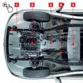
Assignment of elements on the GAZ instrument panel

1 - the voltmeter indicates the voltage in the on-board network of the GAZ car;
2 - control lamp of the engine control system;
3 - reserve (or a control lamp of an abs malfunction on a Volga GAZ car equipped with an anti-lock braking system);
4 - light board "STOP". Lights up simultaneously with one of the warning lamps of malfunctions, if further movement with this malfunction is prohibited;
5 - control lamp for turning on the left direction indicator. The lamp lights up simultaneously with the left turn indicators. If one of the indicator lamps malfunctions, the control lamp blinks at a doubled frequency;
6 - control lamp for emergency drop in brake fluid level. The lamp lights up when the liquid level falls (below the minimum allowable) in the reservoir of the master brake cylinder. As the brake pads wear out, it is necessary to top up the brake
liquid;
7 - odometer (total mileage counter);
8 - the speedometer indicates the speed of the car;
9 - control lamp for activating the parking brake. The lamp is on when the parking brake lever is raised and the ignition is on. 10 - control lamp for turning on the right direction indicator. The lamp lights up simultaneously with the right direction indicators. If one of the indicator lamps malfunctions, the control lamp blinks at a doubled frequency;
11 - reserve;
12 - warning lamp for not wearing seat belts (installed on some Volga GAZ 31105 cars);
13 or 18 - a control lamp for an emergency drop in oil pressure in the engine lubrication system. The lamp should light up when the ignition is turned on and go out after starting the engine. If the lamp stays on after the engine is running, or comes on while the engine is running, stop the engine immediately and check the oil level. Level OK - Engine is defective. For a car with high mileage, the lamp may light up when the engine is warm at idle;
14 - reserve (for installing additional pilot lamps);
15 - fuel level indicator. The gauge shows the approximate amount of fuel in the tank. The scale has divisions 0 - empty tank; 1/2 - half of the tank; 1 - full tank:
16 - fuel reserve control lamp. The lamp comes on when the remaining fuel in the tank is less than 8 liters; 17 - indicator of oil pressure in the engine lubrication system allows to assess the technical condition of the engine;
19 - control lamp for turning on the heated seats (for GAZ 31105 cars with heated seats);
20 - the coolant temperature gauge allows you to control the temperature of the engine;
21 - control lamp for turning on external lighting (side light);
22 - the coolant overheating warning lamp turns on when the coolant temperature rises above the permissible value;
23 - control lamp for turning on the high beam headlights. The lamp turns on when the high beam headlights are turned on;
24 - button for setting the daily mileage counter to zero. In order to reset the counter readings, press the button;
25 - daily mileage counter. To reset the meter readings, press the zeroing button (pos. 24);
26 - tachometer. The device shows the engine speed;
27 - control lamp for battery discharge. The lamp should light up when the ignition is on, and go out after starting the engine. A lamp burning while the engine is running may indicate a malfunction of the generator or its circuits.
Replacing the old instrument cluster with a new one
Many car owners of a gazelle or Volga car with an old-style dashboard tend to change it to a new-style dashboard, in which most of the indicators are replaced with modern LED ones, and such a dashboard looks much nicer and brighter.

So, to remove the instrument cluster, first remove the lining by unscrewing four screws. Then remove the four screws securing the combination; disconnect the electrical connectors and remove the instrument cluster. Repair the instrument cluster by block replacement of faulty instruments. To replace devices, remove the protective glass and on the reverse side unscrew the fastening nuts of the faulty device.

The reason many drivers install the Gazelle Business dashboard is that it looks better. The second reason why it is worth buying this particular version of the panel is the functionality and the increased number of opportunities to monitor the performance of the car.

The euro-type panel has 2 large dials - a speedometer and a tachometer, as well as 2 small ones, which show the amount of gasoline and the temperature of the coolant. The rest of the information about the status of the nodes and the errors that have occurred is displayed using the lit indicators in the middle of the panel. The simpler design significantly relieves the driver's attention.
Video instructions for installing the panel