To the attention of users of the electronic portal, the site appears to be an easy-to-assemble seven-band graphic equalizer. Externally, the equalizer consists of seven columns (by the number of bands) of LEDs of different colors, arranged in the order of the colors of the rainbow. Each column has 10 LEDs - 10 signal levels.

The schematic diagram of the device is shown above. The audio signal from the output of the music center, sound card of a computer or smartphone goes to the input of a specialized microcircuit MSGEQ7. This integrated circuit from Mixed Signal Integration is a 7-channel spectrum analyzer in a DIP-8 package and a current consumption of 1 mA, and is also. MSGEQ7 is able to extract frequency bands of 63Hz, 160Hz, 400Hz, 1kHz, 2.5kHz, 6.25kHz and 16kHz from the input audio signal:

MSGEQ7 is controlled by two digital inputs Reset (pin 7) and Strobe (pin 4). After the start pulse Reset, it is enough to send seven strobe pulses to the Strobe line, as a result of which, after each strobe pulse, a voltage will appear at the Out output (pin 3) proportional to the content of one of the seven frequency bands in the audio signal.

The MSGEQ7 chip output is connected to the input of the LM3915 level LED indicator chip. This microcircuit has ten outputs, the state of which depends on the input signal level. The circuit is controlled by an ATMEGA328 microcontroller, I decided to use a ready-made Arduino Nano board. There are many projects on the network using as many as seven LM3915 cases. I decided to use dynamic indication and one LM3915 microcircuit. The microcontroller generates a Reset signal for the MSGEQ7 and then issues seven strobe signals. At the same time, it turns on one of the transistor keys of the columns of our indicator and this column displays the signal level from the LM3915, which is connected to the rows of our indicator.

I used seven colors of LEDs (red, orange, yellow, warm white, green, blue, and rose-purple) to display all seven frequency bands. Since LEDs of different colors have different supply voltages, different currents and different brightness, in order to get the same luminous flux during the operation of our screen, I used the ability of the LM3915 microcircuit to set the output current. With each column switch, the microcontroller, depending on the column number, using PWM (PWM) and a simple RC filter, forms a voltage at pins 6 and 7 of the LM3915, corresponding to the required column brightness. Thus, the problem of uneven brightness of different types of LEDs is solved. The only thing that was required for this was to raise the PWM frequency of the Arduino from the default 500Hz to 64kHz (the first two lines in the setup section of the sketch).

As far as I know, sometimes not quite high-quality MSGEQ7 copies come across. Characterize their output noise even when the input is grounded. Those. even in the absence of a signal, chaotic emissions will be visible on the screen. Apparently I came across just such a microcircuit. Therefore, I additionally add a signal to the ADC of the microcontroller (A7) from the Out output. With a few lines of code, the microcontroller analyzes the input signal and suppresses the display of noise by simply not turning on the column key.
The sketch for the microcontroller is shown below:
| #define STROBE_PIN 11 // MSGEQ7 PIN 4 #define RESET_PIN 12 // MSGEQ7 PIN 7 #define PWM_PIN 10 // BRIGHTNESS CONTROL #define SOUND_PIN A7 // SIGNAL LEVEL ANALYSIS byte band_pins \u003d (2,3,5,6,7,8,9); // PORTS OF COLUMNS void setup () ( void loop () ( void MSGEQ7 () ( |
As noted above, I used an Arduino Nano board - the only thing I had to "modify" was to remove the USB power protection diode and replace it with a jumper. The voltage "sank" on it and the circuit was unstable. There is also an electrolytic capacitor with a capacity of at least 1000 microfarads for power supply, so that at the moments when almost all the LEDs are on on the screen, the voltage on the USB bus does not sink. It is also worth noting that when powering the circuit from a computer's USB, it is better to use a USB hub with external power supply, this minimizes interference on the USB bus. No PCB has been developed for the equalizer, the whole structure is assembled on two breadboards. In the video below you can see how the equalizer works.
Graphic equalizer schematic diagram and microcontroller code available from
These original light columns are made of single square air filters, black adhesive tape and LEDs. Also used small materials at hand. The advantages of the design lie in its originality and ease of manufacture, and its weight is negligible. In fact, such a design is quickly collapsible, which makes it easy to transport and use. The air filters used in air ventilation systems measuring 20 "x 20" were taken as a basis.
Then they are glued together with ordinary black adhesive tape and cardboard triangles are added to the top and bottom of the cube as reinforcements of the structure. In fact, the cubes in the column may not even be fastened together, but for reliability they can also be glued with 3M tape.
Powerful single LEDs of various colors are used as a light source, installed on the bottom of the column together with a power supply.
With a certain imagination, you can create various lighting effects, implemented on the basis of RGB LEDs using various controllers and other hardware.
Source: churchstagedesignideas
By
The LED Halloween costume for a boy is a great gift! What do kids love most about the holidays? - these are two things - so that everything shines and shines, and also different games in disguised superheroes (or villains). Why not combine the two? Demon costume features: voice filter (Wave Shield), animated LED matrices that make up the face, El glowing wire for the wings and horn. The costume's first debut was recorded on an Internet video from Halloween in the United States. There are two good ideas for a quality suit to watch out for:
- First of all, it's worth noting that there is no carefully planned plan for creating a costume. Electronics doesn't have to be complicated, the main thing is - don't be afraid to experiment and "play" with the craft, because your main goal is to arrange a great Halloween for children. Try to even develop your own ideas. So, the project itself: - The software creators of the project wrote open source code, which you can use in part or in full, or completely adapt the code to create your own projects;
- The project does not provide for step-by-step work to complete the costume as instructed. Almost all electronic components are manufacturing parts of other devices. Relevant instructions:
- Use additional animation as multiple LED lines (like a garland on a Christmas tree). This is for illustrating the wiring of the LED arrays that form the face. There is also an idea to combine the work (mimicry) of the face with the Shield Wave (voice filter) in order to pre-play the pre-recorded sounds in a "terrifying" voice; - Use the ability to combine the Wave Shield with a microphone in order to improve the quality of the modified voice. There are two programs for this clever idea: "adavoice", when only the voice changes, and the "adavoice_face" program, which additionally activates the glow of the LEDs to the changed voice, creating an interesting animation of the face. The latter is what is used as a demon's facial expression; - Work with wires;
- Work with the shape of the demon's face (it's best to just buy a plastic mask), and then with the wings (made of cardboard) and with the horns (by the way, they should be hollow, because they will also glow); - Then, attach the LEDs to your sneakers. The last is the costume itself. Here you just need to buy some cheap clothes (preferably dark colors). Tight clothing works best. First, you should sew pants with a T-shirt or jacket, then make a slit so that the suit can be put on, and then simply sew on ready-made electronics in the form of horns, wings and toes.
Security measures
The main thing to avoid is, of course, moisture ingress. It is especially important to avoid getting liquids while wearing the suit (after all, all electronics are near the face). Happy Halloween!
More information on this project can be found on the links below:
https://learn.adafruit.com/animating-multiple-led-backpacks https://learn.adafruit.com/wave-shield-voice-changer
Good luck!
By
Have you ever melted the right things from the fact that a powerful light fell on them? Have you ever accidentally smashed an expensive lighting fixture by accidentally hooking it with your foot? If this story is about you, then you will surely enjoy working with LEDs. It is a shockproof, non-overheating product that consumes only 100W of electricity while it burns like a 500W halogen lamp. After reading this article, you can understand how you can do this in your own home with your own hands in a simple way. Everything is easier than you might imagine. The assembly process begins by attaching the components to the radiator. The heat sink is used to cool the high power LED. Using special holes in the LED and bolts, attach the LED module to the heatsink as shown in the figure. It is imperative to use thermal paste and press it as tightly as possible to the radiator. Next, we attach the fans that will be used for active cooling. You can take fans that are installed in servers. Next, connect all the parts together, check the operation of the fans, the voltage on the power adapter and fans should be the same. 5V DC or 12V DC. For reliability, you can use its own mini adapter for each fan. Connect power to the LED (the power supply wires from the power source must be soldered to the LED) and test operation by applying voltage to the power source. Be sure to check that the cooling system is working properly. An infrared temperature gun is best for determining the exact temperature.
AC adapter - for fans. The current source is for the LED module. The next step is to place the entire assembled structure in a special pre-prepared frame. It is imperative to make a hole at the bottom for the fans for the cooling system to work correctly. Do not forget to also make several holes at the top so that air enters through them, ventilates all work items, takes heat from them, and then blows out through the fans. The fan board can be borrowed from the charger. Do not use a used or suspicious adapter. If it fails, the powerful LED will overheat and stop shining altogether. Or the day, month, year will lose brightness quickly. You now have a powerful LED floodlight that works like a 500W halogen lamp. It is the same size, as strong and lightweight, which guarantees the convenience of working with the lighting fixture. It is also important that the lamp operates at a temperature of 50 ° C, which allows the LED to work longer than 40,000 hours declared for a temperature of 65 ° C.
By
Very soon everyone's favorite holiday is Halloween. How to make an original mask? The masquerade LED mask will be visible both day and night! There are three ways to decorate your mask with LEDs. This guide will allow you to make a mask of any complexity: all you need is a few LEDs and a battery, no programming or microcontroller is required! You need the skills of soldering and gluing particles, the operating time is no more than an hour. You can make the mask more complex, add animation, but this will require programming skills. But make the best masquerade mask with animation and audi by adding a little audio controller. It will shine day and night, and the animation will play to the music.
Although each mask is made of different electronic components, there are several tools and supplies you will need to use, regardless of the design you choose:
- masquerade mask
- LEDs with drivers / LED strip digital
- glue
- scissors for stripping wires
- soldering iron
- RGB mini / arduino controller / miniature battery compartment
For the first option - a simple masquerade mask with LEDs - you will additionally need miniature batteries. It is necessary to connect the battery pack to the LEDs.
It is easier to solder wires to LEDs on the factory plate, if there is none, you can fix them in any convenient way on any other surface using 3M glue
The next step is to glue the LEDs to the masquerade mask. Take a hot glue gun and carefully glue them in the right place - on the face of the mask or behind the first row of feathers, also glue the battery behind the feathers, so to hide it, if you do not have a heat gun, use superglue.
Leave the mask to dry on the stand for an hour.
To add animation - purchase a dedicated controller to control each LED in the hotel, as in the picture below
making such a device is quite difficult without certain programming skills, a mask with animated lighting
Using a miniature microphone, you can make a mask that will react to sound and change the color of the LEDs.
A miniature speaker can also be installed, which will reproduce various audio effects.
Visually, the mask will not change, but the soundtrack and color animation will make the masquerade mask the best addition to your carnival costume.
If you want to surprise everyone, a sensor that reacts to alcohol can be installed, you get something like a breathalyzer!
As an example of the operation of this sensor, you can see another project Interactive LED bathrobe
Source: https://learn.adafruit.com/led-masquerade-masks/overview
By
We will prepare the materials that we need:
1. Glasses;
2. Glue;
3. Pencil;
4. LED lamps;
5. Chalk board or ordinary (better black, it looks even more impressive);
6. Drill;
7. Socket;
1. The first thing we need to do is buy 100 plastic glasses, it is better to take not ordinary, but colored and dense glasses, the more original the glasses are, the more creative the lamp will be. Lamps can be bought either in hypermarkets such as Auchan, or ordered from online stores (aliexpress, ebay). Picture 1
2. We also need a board, you can take a regular one, or you can take a special chalk board (on it you can draw a lamp frame with multi-colored crayons, constantly changing it, depending on your mood), the second, by the way, is much more expensive. If you take chalk, then its size should be 110 * 110 cm, cups will take 1 m2, the rest of the place will be taken by the frame. If you choose an ordinary board, then its required size is 100 * 100 cm. Choose the color of the board yourself, taking into account the light of the glasses. Figure 2
3. The next step is to choose a Christmas tree garland or LED modules. The power of the lamps must be good, otherwise the light will not penetrate through the dense walls of the cups. The lights themselves should not be small, but about 1 cm, otherwise, inserting them into special holes, they will also give off light poorly. An example of a garland in Figure 3.
4. Using glue, glue the cups one by one, taking up the entire space (if you chose a regular board) or step back 10 cm from the edge (if you have a chalk board). Choose a universal glue that interacts with both wood and plastic. Regular super glue can corrode plastic. Figure 4
5. After the glue is completely dry and the cups are well attached to the board, turn the board over. Using a pencil, mark the centers of the cups' circle. Then drill a hole in the marked places. This is where our LED backlight will be located. Figure 5.
6. Insert the garlands into the holes of the light bulbs, start at the top and arrange them with a snake. The end should be close to the outlet so you don't have to use an extension cord. Figure 6.
7. Voila! Figure 7. Place the finished luminaire in the desired location or even somewhere outside. Original and unusual, it not only looks good in the evening when it illuminates the room, but also during the day. Figure 8.
The cost of an LED project is minimal, the lead time is about 3-4 hours.
Then a 12 V, 0.5 A power supply unit is connected, plugged into the network and the star lights up in one specific color.
If you have imagination and certain skills in working with LEDs and controllers, you can add a variety of lighting effects.
You can download files with 3D models of all parts, as well as see the phased production of a New Year's star, in the original instructions at the link:
http://www.instructables.com/id/Vega-The-LED-lit-Christmas-Star/?ALLSTEPS
Good luck with your projects. Do not forget to use your imagination, and then your projects will truly become unique!
By
DIY LED lighting with the help of LED strip is carried out without much difficulty, you just need to resort to the advice of the masters. It is necessary to decide on the required footage of the LED strip and the required brightness. When laying the tape, the frequency of its cutting should be equal to 3 or 6 LEDs, the segments of which, if necessary, are connected using connectors. To attach the finished tape, remove the protective layer of 3M glue from it and glue it to the surface of the base, having previously degreased. Select the power source rating suitable for the tape / tape cut.
Full text of the article
Enjoy reading!
Many have seen cars with equalizers on the rear window on the streets of their city. This is a beautiful and interesting tuning option, which has a lot of positive aspects.
We try to develop and constantly replenish the collection of equalizers with new items. A full range of currently existing models,
However, often we all want to do something of our own - "exclusive". Add a little imagination, and really amaze others. All auto tuning (light tuning in particular) is aimed exactly at this.
Therefore, we decided to try to develop a technology for making a car equalizer with our own hands.
The first option was to try to make it LED. But this approach was immediately abandoned. There are several reasons. First of all, the LEDs will have to be soldered onto the board, moreover, it will be rigid and massive, and on the one hand this is expensive, on the other hand it is very inconvenient to install. The second reason is the huge amount of work. Not only do you need to solder the controller yourself, you also need to solder a bunch of diodes to the board (even if you make only 20 lines and 40 columns, this will be 800 diodes, which will also have a large total power consumption).
In general, this option is not acceptable.
That is why we offer you a very unexpected and surprisingly simple way of making such a device. Moreover, this approach gives you unlimited breadth of design possibilities. You can not only make an equalizer with your own hands, but also make it of any size, in different colors + make drawings and inscriptions!
Also, it can be used not only in a car or at home, but also on clothes or other accessories (at the end of the article we will give a good example on this topic).
So it's time to act!

When all 5 pieces of neon are connected to the wires, you need to check them. We take the controller, connect it to the 12V power supply. We take one neon cord and insert the red wire coming from it into the plug hole, to which the red wire fits. Insert the black wire into the adjacent hole.
Tap your finger on the controller - the neon should light up (the sound sensor will work).

We check all the pieces in the same way. If everything works, let's install it. We pierce a hole in the surface, insert neon into it and carefully glue it along the contour of the picture.

We used superglue. It turned out to be glued, but it was very inconvenient and not reliable. Superglue, as it turned out, does not adhere well to paper.


We put all the pieces of neon in their places.
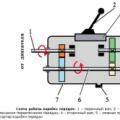
Then we will deal with the connection. First of all, you need to pay attention to the controller plug. The first terminal (to which the red wire fits) is "plus". You will need to connect all the red wires from the pieces of neon to it. Because all of them will not fit there; they need to be twisted and soldered to one, which then needs to be inserted into the terminal.
Then there are the holes for the cons. The one closest to the red hole corresponds to the lowest sound level. Those. the neon, the minus of which is connected to this terminal, will light up first.
The holes following it go in increasing volume. We do not use the last hole. We do not need it (this is another “plus” terminal).
Thus, we connect all the pieces of neon. If everything works fine. If not, then it is short somewhere. Check if the connection is correct.
So - here is a video of our "trial" equalizer. As you can see, everything works. Obviously, this technology has great prospects!
This technology can be deployed much more widely if desired. The blessing exists. You can make a large and complex drawing, with separate sound-dependent elements. You can also decorate individual items. For example, the first thought that came to our mind was to make rings around the speaker and on its grid. A large ring to the outside diameter, and rings with smaller diameters in the center. The result is a circular "rainbow" glowing in time with the music.
We hope that the technology of making a neon equalizer with your own hands is clear to you. Now it remains to show your imagination and make your own design, and even if you have never encountered this kind of work, you can easily handle it in one or two evenings. it is really a very simple thing.
I may not be an avid fan of Justin Timberlake, as the author of this tutorial, but I couldn't help but notice the stunning graphics in his music video for the song LoveSttoned. This tutorial will teach you how to create a similar effect using only good old Photoshop.
Here's what we will achieve:
Lesson materials:
Step 1.Create a new document of size 1024x768 px, background color is black.

Step 2. Open up the equalizer image. I selected the black background of the image using the tool Magic wand (Magic Wand Tool) and removed it by pressing Deleteeven though black matches our main background. Now, click on the area surrounding the equalizer and invert (Ctrl + Shift + I) the selection so that only the rectangular shapes that make up the equalizer image are selected. Select the main color blue (80D2FC) and fill our selection by pressing Ctrl + Backspace. Finally, duplicate this layer, and go to Edit\u003e Transform\u003e Rotate 180 degrees(Edit\u003e Transform\u003e Rotate 180 degrees) then move the copy as shown below.


Step 3. In the layers panel, select both layers with an equalizer and click Ctrl+ Shift+ Eto merge them into one. Now rotate the resulting layer 90 degrees - go to Editing\u003e Transform\u003e Rotate 90 Degrees Clockwise(Edit\u003e Transform\u003e Rotate 90 CW). Now let's copy the layer several times (Ctrl + J) and place the equalizers one below the other. Once done, merge the original layer with all the duplicates.

After completing all these settings, make a copy of the resulting blue path from the equalizers, we still need it. Hide it for now.
Step 4. Duplicate this entire track and click Ctrl+ T - we switched to the mode Free Transformation... At the top right of the screen, you can see the transformation panel. We need to move our row of equalizers to the right - for this we increase the number in the X column, press OK - and our track has moved to the right:


Step 5. An interesting move, isn't it? Use the same commands to make five identical columns as shown below. Once done, merge it all into one layer.

Step 6. Merged all EQ layers? Now let's go in Editing\u003e Transform\u003e Perspective (Edit\u003e Transform\u003e Perspective) and drag one of the top edges towards the center. Make the bottom edges wider if needed. Click OK. We got the following track:

Step 7. Add a mask to the layer. This can be done by clicking on the "Add Vector Mask" icon in the layers panel, or in the menu Layers\u003e Vector Mask\u003e Show All (Layer\u003e Add Layer Mask\u003e Reveal All). Now with a black brush with soft edges we will go along the bottom of our "path".

Step 8. Create a new layer (Ctrl + Shift + N) and with a large white brush, again with soft edges, paint some white spots on the path. Change blend mode (Blend Mode) on Overlapping (Overplay) for a subtle lighting effect.


Step 9. Now select your EQ layer and apply the Outer Glow settings for the layer shown below. Now reduce the Opacity of the layer to about 50%.


Step 10. Now duplicate your EQ layer, and move the duplicate below the original. Apply Filter\u003e Blur\u003e Gaussian Blur (Filter\u003e Blur\u003e Gaussian Blur), and then set Overlay Mode (Blend Mode) layer on Hard Light (Hard Light) and reduce the Opacity (Opacity) to about 30%.

Step 11. Squeezing Ctrland clicking LMB on the mask of the original layer with equalizers, select it. And now, having made the active layer with blur, create the same mask on it. To do this, simply click the Vector Mask icon in the layers menu (F7).

Step 12. Now create a new layer at the very top. Select black as your foreground color and fill this layer by clicking Ctrl+ Backspace... Now go to Filter\u003e Rendering\u003e Clouds (Filter\u003e Render\u003e Clouds). Put Overlay Mode (Blend Mode) layer on Brightening Basics (Color Dodge).


Step 13. Duplicate your clouds layer. We must get a more intense effect. Select your EQ and instrument layer Magic wand (Magic Wand Tool) click on the black area. Now invert your selection so that the "path" is selected. Go back to your second cloud layer and hit Delete, then lower the Opacity to 10%. We got extra fog at the edges of the EQs.

Step 14. Create a new layer. Now select a large brush with 0% Hardness and 100% Opacity. Choose a light blue color (for example 77D1FF). Make some large spots. Reduce the Opacity of this layer to 30%.

Step 15. Now duplicate your original clouds layer and move it above your big brush layer. Blending mode leave Brightening Basics... Now reduce the Opacity of the brushes layer to 20% and the clouds layer to 45%. And also apply a 200px Gaussian Blur on the layer with brushes to slightly "smudge" the effect ( Filter\u003e Blur\u003e Gaussian Blur (Filter\u003e Blur\u003e Gaussian Blur)).


Step 16. Now insert a picture of a person in the center of your picture. The person is on a white background, so it is very easy to select it by pressing Magic Wand on a white background, invert the selection (Ctrl + Shift + I). Copy the person (Ctrl + C), go to our document, paste the person (Ctrl + V). The man should be on the topmost layer! Now change Overlay Mode (Blend Mode) layer on Soft light (Soft Light) and use the tool Eraser (Eraser) to erase his feet, allowing him to subtly blend into the EQ.


Step 17. Now duplicate your person layer and change Overlay Mode (Blend Mode) on the duplicate on Normal(Normal). Now, in any way known to you, make a selection of the light parts of the photo, in this case - the face and shirt. Copy this area to a new layer (Ctrl + J), and hide or delete the previous layer (the whole person and Normal Blending Mode). Going back to the light areas - we don't need a tie (it's dark). Delete it Eraser... Be careful not to snag your shirt!

Step 18. Now for the layer with light areas go to Image\u003e Adjustments\u003e Desaturate (Image\u003e Adjustment\u003e Desaturation) Then, in the same menu, select Color Balance (Color Balance) and apply these settings:


Step 19. Now the fun begins! Remember, I asked you to keep one of the paths. We need him now. Move it to the very top and resize it so that its height is equal to the height of the person. Reduce the Opacity of the layer a little (to about 80%), make two copies of this layer and hide.
Return to the original path. Put it right in front of a man, go in Editing\u003e Transform\u003e Warp (Edit\u003e Transform\u003e Warp) and make something like a wave (look at the kreen below). Make one duplicate visible, place it on the left and do the same, but on this layer, where the narrowing goes in the center, there should be an expansion here. I just can't imagine how to explain it differently, just look at the screen. After making the first duplicate wavy, go to the second and place it on the right to make it look like the screenshot below.

Step 20. Now merge all your duplicated EQ layers together, and go to Image\u003e Adjustments\u003e Brightness / Contrast (Image\u003e Adjustment\u003e Brigthness / Contrast) and set your Brigthness to -100 and Contrast to +100 to make your image black. You need to sharpen the layer, for this we go to Filter\u003e Sharpness\u003e Sharpness+
(Filter\u003e Sharpen\u003e Sharpen More). The edges get sharper and then we use the tool Magic Wand with a tolerance of 50 tapping somewhere outside of our equalizers.
Now invert the selection (Ctrl + Shift + I) and hide our EQ layer. We've got a selection of all three deformed equalizers. Go back to our highlight layer. However, if we now just press Delete, then too much will be deleted. We take Eraser (E) with soft edges and Opacity (Opacity) about 20% and carefully remove only those parts that you think are necessary. IMPORTANT: do not overdo it with your face! Without removing the selection, go to the layer with black parts and work Eraser there.


From the translator: of course, my role here is not great - I'm just a translator. But here is my opinion - the effect on clothes is not very similar to the one in the video. To achieve the best, I advise you to use not an equalizer image, but to create some lines yourself and only then, copying them, delete parts of the clothing.
Step 21. Now create a new top layer and use your tool Pen(Pen Tool) to draw a line near your person. Make sure your current brush is 1px in size, 100% in hardness, and the foreground color is B6FEFE. Draw a path with the Pen, right-click on it and select Stroke Path (Stroke Path). If your line does not suit you with something, you can always change its shape using Free Transformation (Ctrl + T). Finally we will duplicate this layer and move the duplicate slightly below the original. Reduce the width of the second layer so that the lines are slightly different from each other.


Step 22. Merge both layers of lines together and apply Layer Style (Layer Style). In settings External Glow we expose what is shown below. We take a small soft Eraser (E) and erase the edges of the lines a little. Now reduce the Opacity of the layer to 80%.


Step 23. Go to Edit\u003e Transform\u003e Scale (Edit\u003e Transform\u003e Scale) to move our lines a little closer to each other. Now Eraser remove the parts of the lines that go in front of the person's feet. Now create a new layer above all the others and use round white brushes. Gradually decrease the Opacity of the brush to create the effect of fading out the edges of the white lines. Now just put Overlay Mode this layer on Overlapping (Overlay), giving the lines a cool light effect.

Many car owners are trying to give their car special parameters that are not similar to others. Some are trying to improve the technical characteristics of their car, in some cases bringing the performance of a serial car almost to the characteristics of a sports car. Others are trying to increase the cross-country ability of already good off-road vehicles. Such modifications are related to tuning, and a large number of motorists "suffer" from them - from those who have just received a driver's license to "respectable successful uncles".
But such a direction as facelift, which for some reason is also referred to as tuning, is more inherent in young people. They try to give outward appearance to their car by replacing bumpers, installing spoilers, body kits, applying vinyls or airbrushing, equipping the car with high-quality acoustics.
A special place in the facelift is the equipping of the car with additional lighting equipment. In addition to replacing standard optics with more "advanced" and modern ones, the car is often equipped with additional lighting equipment. - now the phenomenon is not so rare.
Recently, another type of car lighting equipment has appeared, which fans have liked to give their car features - equalizers.
Equalizer features

Blue equalizer on the rear window
This equipment creates a luminous image of an equalizer on the glass of a car, which pulses depending on the frequency of the sound of music. In fact, this is the same equalizer that each car radio usually has on its display, but only significantly increased in size. By itself, this equipment does not have any positive function, it simply translates into a light indication the sound of music, which. Therefore, do not confuse this type of equipment with an equalizer, which fine-tunes the sound of music.
The shape of the image for such an equalizer can be different. The most common are columns responsible for a specific sound frequency. The colors of such equipment can be of the same type - they all have the same color, such equalizers, when working, depict only single-color columns increasing or decreasing in height, divided into segments.

There are also multi-colored equalizers. Each column has several types of color segments, each color is responsible for a certain range of sound frequency. For example, a low frequency sound is colored red, a medium frequency sound green, and a high frequency sound blue.
Some expensive models of equalizers may include several types of light images, for example, there are round multi-colored indicator lights on the sides, and columns in the center.
Equalizer sizes can also vary. Some are small and suitable even for use on side windows, while others are large enough to cover the rear window completely.
The most convenient place to install such equipment is the rear window. Its overall dimensions make it possible to equip a car with large-sized lighting equipment. Some also install equalizers on the side windows of the rear doors, but this is not always justified.
How the car equalizer works

Equalizers for the rear window of a car have a relatively simple design. There is a tape on which LEDs are fixed to form segments of columns or circles. Moreover, the tape and the LEDs attached to it are usually transparent, so they do not interfere with the visibility of the car in the daytime. The number of illuminated segments depends on the voltage supplied to them by the control unit. The unit itself is equipped with a very sensitive microphone that picks up the sound in the cabin.
Equalizer setting
This microphone regulates the voltage, which is then supplied to the LEDs. With a weak sound of certain frequencies, the voltage is low, which is why only the lower segments of the columns glow. As the sound frequency rises, the microphone begins to transmit more voltages, which causes more segments to light up.
The entire structure of this equipment consists of a tape with LEDs fixed on it, wiring, a control unit equipped with a power button and adjusting the sound sensitivity of a microphone, as well as an adapter for connecting to the on-board network of a car. This is the peculiarity of the equalizer design. It does not require a connection to a car radio, its operation depends on the volume of the music in the car.
Equalizer installation does not require special knowledge, so everyone can do it.
The LED strip along the perimeter is equipped with an adhesive strip covered with a protective film. To install this tape, it is enough to remove the film around the perimeter and lean it against the rear window of the car from the inside, so that the sticky strip grabs. If it was not possible to stick it straight away, you can carefully peel off the tape and stick it again.
Then this tape is connected to the control unit. A wire is long enough from the unit to hide it around the passenger compartment during installation, in order to avoid damage. It is necessary to lay the wiring so that the control unit is within the reach of the driver. The best option is a storage box between the front seats. There, this block will not interfere. There should be enough wiring to fit this unit between the seats.
Typically, this equipment is powered from the cigarette lighter socket. For this, an adapter for connection is included with the equipment. One end of this adapter is connected to the control unit, and the other is connected to the cigarette lighter socket with a special adapter.
This is the whole connection sequence. All that remains is to check the performance and adjust the microphone sensitivity. To do this, you need to connect the equalizer to the on-board network and turn on the power to the control unit. Then you should turn on the music on the radio and select the microphone sensitivity with the control wheel.
It is not difficult to install this equipment, and given that LEDs are used as light elements, there will be no significant voltage drop in the car's network.
The light equalizer on the glass looks, of course, beautiful. But it should be borne in mind that this is an ordinary lighting equipment that works well only at night. Therefore, if the car is rarely operated at night, and the owner himself is not a music lover and does not like loud music in the cabin, then the equalizer, in fact, is not needed.
Finally, it is worth mentioning the legality of using light equalizers on a car. In the traffic rules there is no clause prohibiting the use of this equipment, therefore there is no penalty for it, although it is quite possible that it will appear soon.
However, in the event of an accident, it may be indicated that the equipment has become a distraction, and this condition already provides for a fine. But here, too, it is still necessary to prove that it was the equalizer that caused the accident.