Materials and assemblies involved in the construction of this all-terrain vehicle model:
1) the internal combustion engine Lifan with a capacity of 15 hp.
2) Four-speed gearbox from the classic VAZ
3) Transfer case from the Niva car
4) Steering fist from Oise
5) Wheels t-150 stripped
Let's consider in more detail the main components of this all-terrain vehicle.
The fracture node was created from a steering knuckle according to the Uvat scheme.
Two belts of profile B are installed, as well as a small pulley for 100 and a large pulley for 300:

The wheel disks were created from T-150 disks, which were wrapped in iron 2 mm thick, and also tacked by welding along the perimeter. The very fastening of the tire to the disk is done with the help of locking wheels, and on the inside, beads are welded to hold the tire. the tire itself is put on the disk with an interference fit, which gives even more strength to the fastening, plus the author used a sealant. Tests will show whether such an attachment is sufficient.

A frame was made from a profile pipe by welding, and bridges from a VAZ 2105 were installed on the frame, the gear ratio is 4.1:

Initially, the author wanted to make the landing on the hub on his own, but it turned out quite difficult and unreliable, so I had to invest more in the all-terrain vehicle.

The assembled weight of the all-terrain vehicle itself is 550 kilograms. The author also started preparing the all-terrain vehicle for sailing.
The axle mountings were painted to immediately notice cracks if they fail the test. Although the structure should not fail, since the washers are scalded on both sides and this should be enough according to the calculations.
The steering was installed. The steering rack was taken from the VAZ 2110, but its stroke is too small and this is not enough for convenient control of the all-terrain vehicle. Therefore, in the future, the author plans to either replace it or install an additional lever in order to correct the direction of movement, as well as increase the thrust stroke.

Then the attachment of the steering knuckle and the rear semi-frame was made in this way:

A fist from an UAZ was used to create a turning unit.
Further, the author considered two ways to create an all-terrain vehicle transmission.
Firstly, you can remove the transfer case and install a chain reducer, then the speed will decrease, but the chains become an additional vulnerability of the all-terrain vehicle, which will need to be worked on.
the frame will have to be shortened, and a more balanced weight distribution of the front of the frame.
Secondly, if you leave the transfer case, you can simply replace the gearboxes with cheap ones with a gear ratio of 4.3. In this case, we also get a decrease in speed, but not as much as we would like.
Regarding the weight distribution, it is possible to cut off the front axle and lift the shank higher, so that the structure is almost close to the transfer case, it is not entirely clear only about the oil level in the gearbox and how this will affect the operation of the system. It may also be worth disassembling the transfer case itself in order to reduce the number of downshifts, but this requires a serious approach to studying the technical documentation.
It is also planned to install a couple of shock absorbers from the zil to strengthen the turning unit:


The all-terrain vehicle was left in the sun outside the garage, the sun warmed up the tires of the car and it spontaneously disassembled, which is rather unpleasant and speaks of insufficient reliability of tire fastening.

Urgent measures were taken to strengthen the fastening:

The steering rack was turned upside down, and a unit that was destroyed under loads was also added, after these actions it became much more convenient to steer.

Yes, the design is rather weak and not reliable, but for a while it will do and it will be possible to test the machine.
The role of the clutch in the all-terrain vehicle is performed by two belts. During a trip on an all-terrain vehicle, one of them flew off for an unknown reason, the author decided not to put it back in the field, but simply to remove it and drive to the garage on one belt. It was noticed that the all-terrain vehicle with one belt feels much better, there is a smooth ride, and most importantly, it starts without jerking.
Regarding the destructible structural element, it was made in this way: one bolt was removed, and the edge was twisted onto an aluminum wire, due to which, under loads, it would be easy to bend the rods relative to each other. It is also quite convenient to adjust the load force by simply increasing or decreasing the number of wire turns.
During the tests, the steering rod broke off, so this element also needs to be improved.
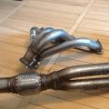
For example, installing a pump from the steering yamz 236.238, since it is immediately made for profile A, instead of NSh-10.
Silent means consent! I'm really sure that setting up these (similar) aggregates will make your life a lot easier. Instead of NSh-10, it is easier to use the pump from the steering YaMZ 236.238, it is immediately made for the belt profile A (if I am not mistaken)
Photo NSh-10, weighing 2.5 kilograms:

Steering system weighing 4 kilograms:

Hydraulic cylinder weighing 5-7 kilograms:

It is also planned to install axles on springs to reduce shock loads on the transmission structure itself, which will increase the speed and smoothness of the all-terrain vehicle. It is possible to modify the hinge by replacing the steering knuckle with three supports and a strut, although the frame joint can withstand the load and justify itself.
But with the wheels, there really are difficulties.
The wheels are very heavy, weighing about 85 kilograms with a disc. In addition, there is no central track - the all-terrain vehicle shakes. So in the future, the author plans to replace them with other lighter ones.
The author also wants to remove the transfer case from the cornfield and install a chain reducer. There is another reason why the author wants to get rid of the transfer case, this is the speed of the all-terrain vehicle. In the first low gear, the all-terrain vehicle moves at a speed of about 5 kilometers per hour, and this is at idle engine speed. This is certainly tolerable, but still too much for the minimum speed, too much load will go to the bridges and the engine itself when overcoming difficult obstacles.
Articulated frame for UAZ.
An overview of the designs of "breaking" frames.
For the average person, the phrase "breaking frame" is associated with a severe breakdown of a truck or SUV.
However, there are engineering solutions that are specifically designed for such an opportunity to "break" the frame without consequences :).
This is done to increase the cross-country ability and maneuverability of the vehicle.
Back in 1919. the Italian engineer Pavesi has constructed the Fiat-Pavesi P4 off-road tractor with extra-large wheels. For turning the car, the "breaking" frame principle was implemented. (source - patriot4x4.ru)


In our country, in 1961, on the instructions of the government, was developed Tractor K-700 with a breaking frame. The goal of the project was to create the first domestic wheeled tractor of the fifth traction class. In the photo, the K-701 tractor

The semi-frame of the K-700 tractor has impressive dimensions

Assembly drawing of the connecting hinge of the K-700 tractor

And who does not remember the city articulated bus Ikarus-280?

The unique properties of vehicles with a breaking frame prompted many designers to implement such a solution in various types of all-terrain vehicles. Moreover, both lonely homemade, and on an industrial scale.
Here, at least recall the Swedish tracked swamp vehicle Elk, which has many imitators.
But there is something to see in the ranks of wheeled vehicles:
SKU snow and swamp-going vehicles
SKU snow and swamp-going vehicles, which were produced by the Severodvinsk company Diphthong, have two sections connected to each other by a pivot-coupling device, which allows the links to fold relative to each other in the horizontal plane.
Snow and swamp-going vehicles are described in the Auto Review magazine 2006
Photo of the swivel joint 
A photo showing that it is imperative to make a turn limiter 
Tractor "Sibiryak"

Sibiryak has an articulated frame 
Most interesting is the central pivot assembly.
It consists of a power case, which is the rear part of the front half-frame, a constant velocity joint (CV joint) that transmits torque to the rear axle, and a ball case, which is hinged and power.
The ball shank is inserted into a special housing of the rear half-frame and has the ability to rotate in it when the relative position of the half-frames changes. The special case is connected to the rear frame with two 20mm plates.
Power case welded from 20 mm thick sheets. perceives the loads acting on the machine in the vertical plane, and the ball bearing, fixed in the tapered bearings of the housing, serves to turn the half-frames relative to each other in the horizontal plane.
This movement is carried out by a swing hydraulic cylinder installed between the front semi-frame and the ball joint bracket.
The basis for the central unit was the parts from the steering knuckle of the front wheel of the ZIL-131 car, identical in design to the GAZ-66 car, but different in size.
The shank of the ball housing and the shanks of the semiaxes of the drive and driven shafts of the CV joint have undergone revision.
The bearings in the axial joint are bronze bushings, and the thrust (longitudinal) forces are taken up by a thrust ball bearing. The hinge cavities are sealed with oil seals and packed with grease.

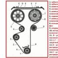
Central pivot point:
1 - bearing 60212; 2- stud M10 (6 pcs.): 3, 10 - thrust rings (steel 45, s2). 4 - king pin; 5 - cuff (from the standard unit); 6 - spring ring; 7 - cuff (1-115x145); 8 - inserts (bronze): 9 - spacer; 11 - persistent nut; 12 - bearing 8212; 13 - locking nut; 14 - special case; 15 - central body of the ball-and-socket joint; 16 - ring; 17 - driven shaft; 18 - ball body; 19 - driving shaft; 20, 26 - bearing housings (steel 45). 21 - flange (cram. 45) 22 - M32 nut; 23 - hairpin М5 (6 pcs.); 24 tapered bearing (standard); 25 - bearing cover: 27 - sealing ring (rubber); 28 - cuff (1-85x110); 29 - steering hydraulic cylinder.
Often, the swivel unit for all-terrain vehicles is made from the steering knuckle of the front wheel of an all-wheel drive vehicle, for example, from the steering knuckle of the UAZ
UAZ-Camper with a rolling frame
Using the technology that had been worked out at the Kaprals, UAZ cars with a twisting frame were made. These are Camper based on the Krasnodar auto club "Kuban" and a truck based on the UAZ-39095

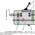
FIG. 1 is a plan view of the vehicle; in fig. 2 the same, side view; in fig. 3 diagram of bearing unloading.
The articulated vehicle 1 with all-wheel drive contains two independent semi-frames A and B, interconnected with the possibility of relative movement. A main hinge 2 is installed between the semi-frames, which has an inner diameter 3, sufficient for the cardan shaft 4 to freely pass through it.
On the semi-frame B, coaxially with the bearing 2, a movable element 6 is installed on the brackets 5 (for example, a shaft mounted in bearings, or a ball joint, or a ball connector can be used as element 6), rotating around axis 7. To element 6 are permanently attached bars 8 and 9. The second ends 10 of the bars are detachably attached to the connecting elements 11 of the half-frame A. The ends 10 of the bars are spaced apart from the longitudinal axis of the vehicle 7.


The vehicle works as follows.
When driving off-road, half-frames A and B can move around the horizontal longitudinal axis one relative to the other at an angle of up to 23 °. The possibility of mutual movement is provided by the hinge 2 connecting the half-frames A, the rods 8 and 9, rotating on the element 6 and tracking the movement of one half-frame relative to the other, unload the hinge 2 and increase the area of \u200b\u200bits operability (see Fig. 3). The arising longitudinal force loads between semi-frames A and B are perceived primarily by connectors 8 and 9, since they are rigidly connected (without backlash), are partially damped due to their own elasticity, and then are transferred to hinge 2.
When driving on public roads, the power frame works in the same way as when driving off-road, taking maximum loads and unloading the hinge 2.
The hinge in the inoperative position is fixed with pins on both sides, which allows the car to move comfortably on public roads. (pins removed in the photo) 

Blueprints 

Inside the hinge (bearing) there is a cardan to the rear axle and all communications:
wires, brake pipes, air hoses. 

This design was initially tested on a UAZ-VD "VARAN" utility vehicle


It was built for fishing trips, picking berries and mushrooms. The author tried to use the most available parts to save money, so that the all-terrain vehicle was budgetary. The all-terrain vehicle was built by the author together with his father, who was engaged in all welding work.
Materials and aggregates used to build this all-terrain vehicle:
1) bridges from the car Moskvich 412
2) FZD engine with forced air cooling
3) steering knuckle from Oise
4) reverse gear from SPD
5) additional chain reducer
6) steering from m-41
7) vi-3 lightweight wheels
8) shaped tube
9) hub from vaz 2108
Let's consider in more detail the stages of construction and the main units of the all-terrain vehicle.
To begin with, two half-frames with a size of 1600 x 700 were welded from a profile pipe. the all-terrain vehicle bridges were installed in the middle. And also a frame fracture node was made from the UAZ steering knuckle according to the Uvat scheme.

After that, work began on the creation of disks for the all-terrain vehicle. The design of the discs was made as simple and reliable as possible. The diameter of the locking rings is 510, although it was originally planned to be 530. True, this did not play a strong role.


Then the author proceeded to work on the back of the half-frame.

Then the marking of the main elements and their layout in the all-terrain vehicle began. In particular, the author decided to see where it is better to install the engine subframe.
At the same time, work continued on individual designs of the all-terrain vehicle. A propeller shaft was made, which transmits rotation from the gearbox to the hub of the VAZ 2108, and then through an asterisk to the propeller shaft of the Muscovite bridge.


The main turning work was carried out by order of a specialist in this business.
Below you can see how the hub connects with the Muscovite shank.


Then the steering rack was installed from the m-41. The rail was installed according to the Uvat scheme:


Here it is shown how the steering rod from the Oise and the m-41 was spliced:

Welding works were performed on the front semi-frame of the all-terrain vehicle:


The gearboxes in the bridges of the Muscovite were turned over, and a gearbox from the SPD was also installed.


After the gearbox was disassembled, the author welded a differential in it and proceeded to assembly, followed by installation in its place in the design of the all-terrain vehicle.
After the two front wheels of the all-terrain vehicle were completed, the author decided to install the roof:

On the rear, a 40 x 25 profile with a thickness of 2 mm was used. moreover, a cut was made on the last upper profile in order to be able to put on the ring. On the front two wheels, the lower profile is of the same size 40 by 25 and 2 mm thick, and the upper 30 by 30 mm. The creation of the front wheels was much easier and the wheel was easy to dress, in contrast to the design of the rear wheels.
After completing the main work on the transmission of the all-terrain vehicle, the author proceeded to field tests of the vehicle. after the first tests, some design flaws of the all-terrain vehicle were identified. In particular, they consisted in the incorrect operation of the all-terrain vehicle clutch, as well as gear shifting. Therefore, the author began to refine the transmission from the engine to the gearbox and clutch. For this, the native motorcycle clutch cable was replaced, as it squeezed too hard, which did not give smooth gear shifting. An exhaust pipe was also installed on the all-terrain vehicle in order to reduce the noise of the car.