The cooling system of the VAZ 2114 is of great interest to motorists. Model 2114 machines have a hidden cooling system based on the use of a special cooling mixture. The movement of the coolant mixture is driven by a mechanical pump.
The principle of assembly of many Russian cars is carried out rather poorly, therefore the performance of many mechanisms, including the cooling system of the VAZ 2114, leaves much to be desired.
To identify and carry out the necessary repair work, you need to have an idea of \u200b\u200bthe state and method of operation of the cooling system.
The cooling system of the VAZ 2114 engine has a big drawback, because requires constant monitoring, frequent maintenance and necessary repairs.
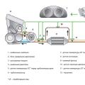
Cooling system diagram VAZ 2114
Cooling scheme VAZ 2114 : 1 - element in the form of a plug for the expansion tank; 2 - expansion tank; 3 - hose for removing liquid from the branch pipe; 4 - hose passing between the radiator and the expansion tank; 5 - outlet hose from the radiator; 6 - a tank to the left of the radiator; 7 - aluminum tube; 8 - plug systems; 9 - a tank to the right of the radiator; 10 - drain plug; 11 - the middle of the radiator; 12 - casing for an electric fan; 13 - plastic wings of an electric fan; 14 - electric motor; 15 - gear pump pulley; 16 - pump impeller; 17 - camshaft drive belt; 18 - block for the engine; 19 - pumping pipe; 20 - a hose for a radiator with a supply function; 21 - heater radiator hose with outlet function; 22 - hose supplying coolant to the throttle pipe; 23 - outlet pipe; 24 - refueling hose; 25 - heater radiator hose with supply function; 26 - thermostat; 27 - coolant temperature sensor; 28 - coolant level indicator sensor.
The principles of the cooling system 2114
The performance indicator is based on the internal heat exchange provided by the cooling mixture. This option is most effective.
The movement of the coolant mixture is carried out by forcing under the influence of a pump powered by a drive belt. The cooling mixture is filled into the system by pouring it into the expansion tank. depends on the volume of the motor.
The electric fan is installed on the shaft of the electric motor, the work is based on the readings of the sensor, thanks to which it begins to perform its functions, or stops them.
The cooling system is of great interest to motorists. Model 2115 machines have a hidden cooling system based on the use of a special cooling mixture. The movement of the coolant mixture is driven by a mechanical pump.
The assembly principle of many Russian cars is carried out rather poorly, so the performance of many mechanisms, including the cooling system, leaves much to be desired.
To identify and carry out the necessary repair work, you need to have an idea of \u200b\u200bthe state and method of operation of the cooling system.
Airlock
If you have a 1.6 liter engine, then the first thing to do is remove the plastic cover on the engine - unscrew the cover on the engine to fill in oil, and then pull out the entire cover. It is seated on rubber seals. After removing this plastic screen, we screw the oil cover back in order to avoid dirt getting into the engine crankcase.
- We find the heating pipes of the throttle assembly (there are 2 of them), see the figure. We pick up any phone
- We begin to blow into the tank with liquid. We blow until all the air comes out of the hose and the antifreeze flows.
- Quickly put the tube back on and tighten it with a clamp so that no air gets there.
(It should be noted that depending on the tube that you removed, the antifreeze may flow both from the tube; and from the fitting from which the tube was removed)
The second way to remove air from the cooling system is less perverse. There is no need to blow anything here:
- We warm up the engine to operating temperature
- Warm up, turn off the engine
- The expansion tank cap does NOT need to be unscrewed.
- As in the first method, we unscrew the clamp of the coolant pipe on the throttle assembly.
- After removing the heating pipe of the throttle assembly, release the air, and after the antifreeze begins to flow out, immediately put it back on the fitting and secure it well with a clamp.
But be careful and careful! Do not forget that the temperature of the coolant is approximately 90 degrees.
There is also an easier, but less effective way to eliminate the airlock:
1) We drive up a steep hill so that the radiator cap becomes the highest point of the cooling system.
2) Unscrew the expansion tank cap and radiator cap.
3) Let the car warm up to operating temperature
4) Then we gas it several times and in parallel pour coolant into the barrel.
We do it until the bubbles stop appearing.
Replacing nozzles
The cooling system uses 4 rubber pipes:
- the upper inlet pipe - supplies the cooled liquid from the radiator to the engine;
- lower outlet pipe - removes the heated liquid from the bottom of the engine to the radiator;
- two short pipes that connect a water pump and a thermostat to the system.
In case of failure, the pipes must be replaced. In this case, it is best to purchase silicone tubes.
To remove old and install new silicone (rubber) pipes, you must have a set of wrenches, several screwdrivers and silicone grease.
Repairs associated with replacing pipes must be carried out in the following order:
1. Disconnect and remove the battery;
2. Drain off all the cooling mixture;
3. Remove the fan, noise-insulating upholstery, trim and frame trim from the windshield;
4. Free access to the air collector, for which remove the elements of its fastening;
5. Remove the front housing and release the clamps that hold the pipes;
6. Remove the branch pipes from the fittings and install new ones (silicone or rubber) in their place. Secure the new connections with clamps. Before installation, it is recommended to lubricate the rubber pipes with silicone grease. It is also advisable to lubricate the clamp screws with silicone grease. Subsequently, this will allow you to easily unscrew them;
7. Put all the removed parts in their places, flush the system and fill it with new coolant mixture.
How to rinse
Flushing the cooling system with water
Although you can flush the system with water, I would strongly advise against doing this. As I said, it contains a large amount of impurities and salts that form scale. If there is no other option, then use at least distilled water. The cooling system is flushed with distilled water as follows:
- Pour water into the SOD.
- Start the engine and let it run for about half an hour.
- Then stop the engine and drain the water from the system. Repeat the procedure until your flushing fluid is the same as before flushing. The disadvantages of this method include: the formation of scale, low efficiency (boiling water is not able to dissolve and wash off scale and other deposits).
Flushing the cooling system with water, acid and vinegar
Water with vinegar and acid is a little better than just water, because thanks to acids, you can remove scale and partially clean the cooling system. In order to flush the system in this way, prepare: caustic soda, lactic acid and vinegar. The acid is added carefully and little by little, if you overdo it, you can say goodbye to the plastic and rubber parts of the cooling system. It takes 5-10 hours to completely remove scale and dirt, during which it is necessary to periodically warm up the engine to operating temperature. At the end, all the liquid is drained and the distillate is poured, which is used for the final flushing of the cooling system.
SOD flushing with special chemicals
Specialist. funds are the most effective and expensive option. However, the effectiveness of such a procedure is worth overpaying. The cleaning agents contain special cleaning agents that actively remove scale, grease, organic matter, etc.
Flushing specials funds are divided into four types: acidic, alkaline, two-component, neutral type.
Acid and alkaline are considered the least popular, and it is almost impossible to find them undiluted. This is due to their aggressive effect on the entire cooling system, in essence plastic and rubber products.
Two-component products are very popular and highly demanded. Their 2-component solution consisting of alkali and acid does the job well. Each of the components is poured into the radiator in turn.
In the composition of neutral cleaning agents for the cooling system, there are no aggressive substances, such as acids or alkalis, and they are used exclusively for preventive purposes.
After a strong heating of the VAZ-2115 engine, the probability of its complete combustion increases. To prevent this from happening, it is necessary to constantly monitor the cooling system. Newcomers believe that the injection mechanism does not require regulation, but this is not so - for the VAZ-2115 engine, the injector does not change anything.
To be able to independently maintain the cooling system, to correct defects and breakdowns means saving a certain amount of money and time. What factors do the VAZ-2115 cooling system require to control?
- Correct operation of all components.
- The degree of tightness.
If there is even one of the problems mentioned above, it's time to start repairing. It is not worth delaying the repair work - the engine is too expensive to experiment with, and even more so to wait for its combustion.
How the VAZ-2115 cooling system works
The VAZ-2115 has the same cooling system as other injection-type cars. The principle of operation is based on heat exchange, which takes place with the help of a liquid. The latter can be antifreeze, cooling antifreeze, in extreme cases, water, although experts do not recommend using the latter option.
The cooling system diagram built into the VAZ-2115 consists of the following key components, indicated in the photo:
- electric motor;
- pump - provides the movement of the filled liquid throughout the system;
- radiator;
- thermostat - regulates the activity of all components of the structure.
The circulation of the coolant through the pipes is provided by a centrifugal pumping device. Enabling and disabling the sensor depends on the values \u200b\u200bshown by the sensor.
The temperature regime available in the VAZ-2115 is also important. If the indicators exceed the set 87 degrees, the following occurs:
- the thermostat valve comes into action and opens;
- the liquid for cooling goes to a large circle of circulation, which involves passing through pipes through the engine and cooling the latter;
- the fan comes into operation, it begins to supply air flow to the radiator grill, and this helps to reduce the temperature.
Among all the components of the cooling system, experts call the most important one, without which the integral mechanism could not work properly - this is the valve coming from the thermostat. The part consists of technical wax that deforms under certain temperatures. This is how the volume of coolant supply is ensured, the cooling intensity is regulated.
Causes of breakdowns in the VAZ-2115 cooling system
 Nothing lasts forever, so the cooling system can also break. Every motorist can cope with a malfunction, it is not difficult to do it with his own hands, especially since you now know how the circuit of the VAZ-2115 cooling device looks and works.
The engine cooling system is far from the most minor element responsible for the normal functioning of the car. The problems associated with normal engine cooling are of interest to any car owner. It is about this, and about how you can improve the work of this element of the car, and we will talk in our article.

Disadvantages of a basic cooling system
The main reason why it is very often necessary to refine the cooling system of the VAZ 2114 is the uneven operation of this very system. So, when the stove is turned on, the heating of the interior, although it happens very slowly (especially when starting the car after parking with the engine turned off), still happens. But, when the system reaches 80 C, heating stops abruptly and cooling occurs.


The opposite situation also occurs in summer, when the operation of the fan shows itself completely unsatisfactory, and it is extremely difficult to be in the car (if no additional air conditioner is installed).
All these shortcomings are caused by the imperfection of the cooling system itself, and we will tell you how to fix them below.
Why modernization is needed
It should be noted right away that the alteration of the cooling system of the VAZ 2114 is not a prerequisite for the normal operation of the car.
Its main goal is to achieve maximum comfort in the passenger compartment both in hot and frosty weather. It will help to avoid excessive heat or cold inside the car and will save you from sudden temperature jumps (typical, by the way, of all other cars from AvtoVAZ - after all, they all have a cooling system built according to one general principle).


The most likely reason for the poor performance of the system is considered by many to be a radiator, which really does not have a high throughput, others sin on the pump (and in some cases it is really his fault).
But, as serious studies have shown, the main reason for the poor performance of the cooling system is its thermostat. After all, it is this part that is responsible for the uniform heating of water and its protection from excessive heating or freezing.
Modification of the thermostat activation system according to the diagram below will help to avoid such troubles as:
- Long heating of the passenger compartment after parking.
- Temperature jumps while driving.
- Poor cooling in summer heat.
- Uneven heating of the passenger compartment.
How to upgrade the system
The simplest scheme for modifying the cooling system of the VAZ 2114 is to replace in places the branch pipe extending from the stove and the branch pipe extending from the expansion tank. Thanks to such a simple and quick modernization, the following happens: during its operation, the car engine heats up the coolant, which then enters the thermostat.
From the thermostat, part of the coolant goes to the stove, and the other part to the pump and from there to the engine (a small circle goes through). Part of the liquid supplied to the stove gives off some of the heat and, in a somewhat cooled form, enters the thermostat again.


The thermostat mixes the coolant coming from the stove with the heated fluid coming from the engine. As a result, the overall temperature of the liquid decreases (due to the cooled coolant from the stove) and the valve does not open. Due to this, the thermostat valve will open only when all the liquid in it has a temperature of +85 C.
As you can see, the circulation of the liquid and its temperature in the system will become much more uniform and will not have sudden changes, as when using the "classic" scheme installed from the factory.
For this arrangement, a 6-hole thermostat ("new design") must be installed. If for any reason there is a thermostat with 5 holes, then it should be replaced with the specified one.
When preparing to tune the VAZ 2114 cooling system according to the above scheme, it should be remembered that when replacing the pipes in places, their length will not be suitable - one will be longer and the other shorter. That is why, in order to perform the required procedure, you will need to purchase new pipes and adjust them in length, or make them yourself.
For this whole procedure, you need a minimum of tools:
- crosshead screwdriver;
- pliers;
Before dismantling the nozzles, put a cloth under them in order to avoid a coolant spill.


When fixing the pipes with clamps, it is important not to apply excessive force. Excessive tightening can soon lead to destruction of the pipe material.
By upgrading the cooling system in this way, you can achieve the following results:
- Even in the most severe frosts, the interior of the car will be warm (thanks to a more even circulation of liquid and an increase in the efficiency of the stove, on average, by 20%.
- In the summer heat, the cooling of the passenger compartment will be almost 2 times more effective (after all, the speed of fluid circulation will more than double).
- The operation of the car engine will become more uniform and smooth, the "failures" characteristic of VAZ (and other cars of domestic production) will disappear.
In addition to all this, the readings of the temperature sensors will now show the true temperature, which exactly corresponds to the temperature in the system.
As you can see, a very simple and quick (the replacement itself can be performed in a few minutes) procedure helps to solve a number of serious problems at once. It is also worth noting that such tuning can be performed not only on 2114, but also on other VAZ cars.
Useful video
For more information on this issue, you can glean from the video below:
FEATURES OF THE DEVICE
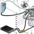
The design of the cooling system is shown in Fig. 2-57.
Figure: 2-57. Cooling system:
1 - expansion tank plug; 2 - coolant level indicator sensor; 3 - expansion tank; 4 - coolant temperature sensor; 5 - outlet branch pipe of the water jacket; 6 - hose for supplying coolant to the throttle branch pipe; 7 - steam outlet hose; 8 - radiator supply hose; 9 - left radiator tank; 10 - impeller of the electric fan; 11 - radiator tubes; 12 - the right radiator tank; one 3 - radiator drain plug; 14 - casing of the electric fan; 15 - electric fan; 16 - timing belt; 17 - a pulley of the coolant pump; 18 - impeller of the coolant pump; 19 - radiator outlet hose;2 0 - supply pipe of the coolant pump; 21 - hose for removing the coolant from the throttle pipe; 22 - heater radiator outlet hose; 23 - heater radiator supply hose; 24 - thermostat; 25 - filling hoseThe cooling system is liquid, closed, with forced circulation of liquid, with an expansion tank.
Centrifugal type coolant pump
driven by the timing belt 17 of the timing mechanism.The electric fan has a plastic four-blade impeller 13 mounted on the shaft of the electric motor 14, which is switched on and off by the controller.
Thermostat 26 with solid thermosensitive filler has a main and an additional valve. The main valve starts to open at a coolant temperature of 85 + 2 ° С, the main valve travel when the temperature reaches 102 ° С is not less than 8 mm.
Radiator tubular-plate, aluminum, with plastic tanks 6 and 9, two-way, with a partition in the left tank. The coolant is poured through the filler neck of the expansion tank 2, the plug 1 of which has inlet and outlet valves. The pressure of the beginning of the opening of the outlet valve is not less than NO kPa (1.1 kgf / cm 2), the inlet one is 3-13 kPa (0.03-0.13 kgf / cm 2).
CHECKING THE LEVEL AND DENSITY OF THE COOLANT
With a fully charged cooling system, the coolant level in the expansion tank should be 25-30 mm above the "MIN" mark on the expansion tank when the engine is cold.
WARNING. It is recommended to check the coolant level on a cold engine, since when it heats up, the volume increases and the level of the liquid can rise significantly in a warm engine.
If necessary, check the density of the coolant with a hydrometer, which should be 1.078-1.085 g / cm 3.
If the level in the tank is below normal, and the density of the liquid is higher than indicated, then add distilled water. If the density is normal, add the same grade of fluid that is in the cooling system. If the density of the fluid is below normal, add Tosol-A fluid.
REPLACING THE COOLANT
Replace in the following order.
Unscrew the cap 1 (see Fig. 2-57) of the expansion tank 2.
Remove the engine mudguard by unscrewing the bolts securing it to the body.
Place a container under the engine to drain the fluid, unscrew the drain plugs of the radiator and cylinder block and drain the fluid. Screw the plugs back on after draining.
Fill in coolant through the filler neck of the expansion tank 2, having previously disconnected the hose 3 from the throttle pipe. If liquid appears in the throttle fitting, put the hose back in place, add liquid to the level of the upper edge of the retaining strap and screw the plug.
Start the engine and let it run for 1-2 minutes. idling to remove air locks.
Stop the engine, check the fluid level. If the level is below normal, and there are no signs of leakage in the system, then add coolant.
COOLANT PUMP
Disassembly. To disassemble the pump, do the following:
Press with a puller 3 (Fig. 2-58), fixed in a vice, pulley 2;
Unscrew the locking screw and press out the roller assembly with the bearing with a mandrel 67.7853.9569,
impeller and oil seal. Apply force to the bearing race;Press the impeller off the roller and remove the oil seal.

Figure: 2-58. Removing the pump drive toothed pulley:
1 - pump housing; 2 - toothed pulley; 3 - pullerThe control. Check the axial bearing play. This operation must be done without fail if there is significant pump noise. The gap should not exceed 0.13 mm at a load of 49 N (5 kgf). If the clearance is larger, replace the bearing with the roller with new ones.
It is recommended to replace the pump oil seal and the gasket between the pump and the cylinder block with new ones during repairs.
Cracks and deformations of the case are not allowed.

Figure: 2-59. Coolant pump with reference dimensions for assembly:
1 - bearing locking screw; 2 - pump housing; 3 - cylinder block; 4 - impeller; 5 - bearing roller; 6 - persistent sealing ring of the stuffing box; 7 - rubber gland seal; 8 - bearing; 9 - toothed pulleyAssembly. Assemble in the following order:
Using the mandrel 67.7853.9568, install the oil seal into the body, not allowing it to skew;
Press in, applying force to the bearing cage, the bearing with the roller so that the holes for the locking screw 1 coincide (Fig. 2-59);
Tighten the bearing retaining screw and stamp the contours of its seat to prevent self-loosening;
Using special tool 67.7820.9527, press on the impeller and then a new toothed pulley 9, keeping the dimensions 52 + 0.5 mm and 39.8 + 0.1 mm shown in fig. 2-59;
WARNING. Do not reuse the toothed pulley.
Check the reliability of the pulley connection on the roller by applying a torque of 24.5 N · m (2.5 kgf · m) to the pulley. The pulley should not turn.
THERMOSTAT
The thermostat should check the opening temperature of the main valve and the valve stroke. Install the thermostat on the stand and lower it into the tank with technical glycerin. On the main valve 4 (Fig. 2-60), rest the bracket lever connected with the indicator leg.

Figure: 2-60. Thermostat:
1 - bypass valve; 2 - outlet pipe (to the pump); 3 - main valve spring; 4 - main valve; 5 - piston holder; 6 - piston; 7 - inlet pipe (from the radiator); 8 - rubber insert; 9 - solid heat-sensitive filler; 10 - spring of the bypass valve; 11 - inlet pipe (from the engine)The initial temperature of the liquid in the tank should be 78-80 ° C. Increase the temperature of the liquid gradually by about 1 ° C per minute with constant stirring so that it is the same throughout the volume of glycerin.
The temperature at which the valve starts to open is the one at which the main valve travel is 0.1 mm
The thermostat must be replaced if the opening temperature of the main valve does not correspond to 85 + 2 ° С, or if, when the temperature reaches 102 ° С, valve 1 does not touch the seat of the branch pipe 11 ... The simplest check for a thermostat can be done by touching it directly on the vehicle. After starting a cold engine with a working thermostat, the lower radiator pipe should heat up when the coolant temperature reaches 85-92 ° C.
RADIATOR AND EXPANSION TANK
Removal and installation of them on the car is carried out on a cold engine in the following order (see Fig. 2-61).

Figure: 2-61. Details of the radiator and electric fan:
1 - radiator; 2 - radiator tank; 3 - electric motor; 4- casing; 5 - impeller; 6 - rubber pad; 7 - drain plugUnscrew the cap from the expansion tank. After unscrewing the drain plugs of the radiator and cylinder block, drain the coolant.
Disconnect the electrical wires from the electric fan. Disconnect hoses from radiator 1 and expansion tank.
Unscrew the nuts and bolts of the casing 4 and, holding the radiator, take out the casing assembly with the electric fan. Remove the radiator from the engine compartment.
If necessary, unscrew the fastening nuts, remove the fan and the fan motor.
Remove the fastening strap and take out the expansion tank.
Install the radiator and expansion tank upside-down.
Checking the tightness of the radiator. The tightness of the radiator is checked in a water bath. After plugging the radiator pipes, supply air to it under a pressure of 0.2 MPa (2 kgf / cm 2) and lower it into a bath of water for at least 30 s. In this case, the appearance of air bubbles from the radiator should not be observed.
If damaged or leaky, replace the radiator with a new one.