The car is badly pulling;
Interruptions in the work
Immobilizer is badly triggered (you can not always start the engine)
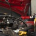
1. First of all, before carrying out diagnostics, we take the MTA-2 pressure gauge, turn the cap on the ramp nozzles, screw the pressure gauge fitting, after having wrapped it with a cloth (so that the gasoline is in case of which he did not hit the hot parts of the engine). After that, you can start the engine. After the pump is powered by pressure, press the valve pressure gauge button so that air bubbles are gone together with gasoline into a gas-resistant container where the thin pipe of the drain is inserted. We look at the testimony of the pressure gauge: on idling Fuel pressure must be within 2.5 -2.6 bar. With a sharp set of revolutions, the pressure should increase to the bar. This suggests that the pressure regulator works fine.
Check the performance of the fuel pump, since the engine under load consumes more fuel, the pump with low performance may not pump the bar., And acceleration will be sluggish. In order to check the performance of the pump, we turn the return on the reverse line (hose from the pressure regulator in the gas tank), and we look at the pressure if it rises to 5-6 bar., The pump is quite suitable for further operation. If not, it is recommended to replace it. The mooring engine, turn on the ignition, the pressure gauge shows the s bar.
In general, the fuel pump is in order.
3. We take and remove the high-voltage wires from the ignition and candle module. We check the wires on the resistance of current-handed lives, it should be within 5..10 kΩ. Everything is fine. We look at the candle, on the candle 1, is clearly observed more black soot than on other candles. Most likely, DMRV is guilty (air flow sensor). Clean the candle and put everything in place.
4. Check the air filter. In order.
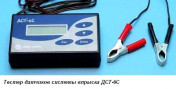 5. Now take the DST-6 and the Cable VAZ, connect it to the DMRV and turn on the ignition. The device shows a voltage of 1.15 volts. This is a clear indication of the sensor fault. A serviceable sensor must produce a voltage from 0.97 to 0.99, and no more, and no less. And on the engineered engine, it should show more than 1.0 volts, about 1.5 and higher at the passage. Well, we found the first fault. Since the DMRV overestimates the output voltage, then the control unit injected more fuel at the same air flow. And this leads to the wrong preparation of the mixture, the mixture is richer. Because of this, the dynamics of overclocking decreases. We put a new sensor, pre-checking it with DST-6. Next, connect DST-6 to the DPDZ sensor (position sensor throttle valve). Include DPDP check mode and open and close several times the throttle valve. When checking DST-6 how many times sound signal and showed that in several places the resistive layer of the sensor there are breakdowns. So the second malfunction was discovered. In principle, this malfunction could be detected using a diagnostic program, but with DST-6 easier to detect this malfunction. Change the sensor DPDZ.
6. We check how the nozzles work. To do this, we will use DST-6, connect DST-6 to the nozzles cable, unscrew the candles so that they do not go hike and, including ignition, pump pressure, or turn on the fuel pump using the Motor Tester program or the DST-2M scanner. And on one nozzle, we open on all three modes, we look at the drop in the pressure of the fuel on the pressure gauge, not forgetting the pressure before each regime. Record the results in the table. And so all the nozzles, then we carry out the results, and with discrepancies, or change defective nozzles. But with our car, the balance of the nozzles showed that the nozzles are normal.
7. Now we connect the car to the computer, and check the presence of errors, we had to have an error caused by a discontinuity of DPDZ, we wash it, as we have already changed the sensor. Turn on the window where there is an "InPlam" graph (the current state of the oxygen sensor), we start the engine and look at this schedule, it is on a warm engine, must, will often change from a minimum to a maximum. If he freezes for a long time in any state, in the poor or rich, then this suggests that he will soon cease to work at all, and will give an incorrect information about the real level of oxygen in exhaust gases. This can lead either to big flow Fuel, or to too poor mixture, which will also adversely affect the operation of the system as a whole. We check the remaining parameters on the computer, and if they are normal, we can say that everything is in order.
8. Check the condition of the idle regulator (RXX). We unscrew it and look at the rod. As expected, all it is covered with black nagar. We connect it to the DST-6 and with the help of the Pxx test, we derive the rod from the sensor. We clean the thread and the cone, splash inside the sensor with a soft cleaner, such as WD-40, it will clean everything inside. Lubricate the thread of the stem with a lubricant, it is desirable that that does not freeze, and again, with the help of DST-6, he has progressed the rod "forward - back", checking that he does not twist, take it to the middle. All, you can put RXX in place.
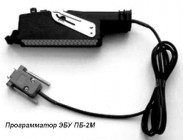 9. We check the immobilizer. In cases where the immobilizer does not "detect" the key, remove the computer, you must first turn off the battery. Take the PB-2M programmer. Connect it to the computer and computer. We feed meals, and launch the PB-2M programmer program. After the connection is established, choose "Clear EEPROM". Now the treatment procedure can be considered complete. All turn off. We put the gun in place. Now the car will start without a key near the reader.
List of variables, Engine control systems VAZ-2112 (1.5l 16 cl.)
controller M1.5.4N "BOSCH"
| № | Parameter | Name | Unit or condition | Ignition included | Idling |
| 1 | OFF | Engine shutdown sign | Well no | Yes | Not |
| 2 | IDLING | Sign of engine operation in idling mode | Well no | Not | Yes |
| 3 | OH GOD. In power | Sign of power enrichment | Well no | Not | Not |
| 4 | Block | Sign of blocking of gophalopodachi | Well no | Not | Not |
| 5 | Zone reg. O 2. | Sign of work in the zone of adjustment by oxygen sensor | Well no | Not | Well no |
| 6 | Zone Deton | Sign of engine work in the detonation zone | Well no | Not | Not |
| 7 | Purge AFS | Symptom of the adsorber purge valve | Well no | Not | Well no |
| 8 | Learning about 2. | Sign of training of fuel feed on the signal of the oxygen sensor | Well no | Not | Well no |
| 9 | Measure member | Sign of measurement of idling parameters | Well no | Not | Not |
| 10 | Last XX | Sign of engine work at idle in past calculation cycle | Well no | Not | Yes |
| 11 | Bl. Out From xx | Sign of blocking output from idle mode | Well no | Yes | Not |
| 12 | Pr. Zona Children | Sign of engine work in the detonation zone in the past calculation cycle | Well no | Not | Not |
| 13 | PRD.DS. | Sign of adsorber work in the past calculation cycle | Well no | Not | Well no |
| 14 | Obn.Donats | Sign of detonation detonation | Well no | Not | Not |
| 15 | Last 2. | Signal state of the oxygen sensor in the past calculation cycle | Poor / rich | Poor | Poor / rich |
| 16 | Current O 2. | Current state of the oxygen sensor signal | Poor / rich | Poor | Poor / rich |
| 17 | T.Chl.zh. | Cooling fluid temperature | ° S. | 94-101 | 94-101 |
| 18 | Pol.D.Z. | Position of throttle valve | % | 0 | 0 |
| 19 | Ob.Dv | Engine rotation speed (discrete 40) | rpm | 0 | 760-840 |
| 20 | Ob.dv.Hh. | The speed of rotation of the engine on x. x. | about/ min. | 0 | 760-840 |
| 21 | Zan.Pol.rkhh. | The desired position of the idle regulator | step | 120 | 30-50 |
| 22 | Tek.Pol.rkhh | Current position of the idle regulator | step | 120 | 30-50 |
| 23 | Cor.Ver.VP | Injection pulse duration correction coefficient at DK signal | elf | 1 | 0,76-1,24 |
| 24 | U.0.3. | Ignition advance angle | ° PK. | 0 | 10-15 |
| 25 | SK.Avt. | Current car speed | km / h | 0 | 0 |
| 26 | Borf.Nap | Voltage B. on-board network | IN | 12,8-14,6 | 12,8-14,6 |
| 27 | J.Ob.Khh. | Desired idle speed | rpm | 0 | 800 |
| 28 | BP VPR | The duration of the fuel injection pulse | ms. | 0 | 2,5-4,5 |
| 29 | Masp | Mass flow of air | kg / hour | 0 | 7,5-9,5 |
| 30 | CYK.RV. | Pokiclovaya air flow | mg / tact | 0 | 82-87 |
| 31 | C. races T. | Hourly fuel consumption | l / hour | 0 | 0,7-1,0 |
| 32 | PRT | Travel consumption of fuel | l / 100km | 0 | 0,3 |
| 33 | Current | Sign of availability of current errors | Well no | Not | Not |
List of variables, Engine control systems VAZ-21102, 2111, 21083, 21093, 21099 (1.5l 8 cl.) Controller MP7.0H "Bosch"
| № | Parameter | Name | Unit or condition | Ignition included | Idling |
| 1 | UB. | Tension in the on-board network | IN | 12,8-14,6 | 13,8-14,6 |
| 2 | Tmot. | Cooling fluid temperature | from | - * | 94-105 |
| 3 | Dkpot. | Position of throttle valve | % | 0 | 0 |
| 4 | N40 | Rotation frequency crankshaft Engine (discreteness 40 rpm) | rpm | 0 | 800 ± 40. |
| 5 | Th1 | The duration of the fuel injection pulse | ms. | -* | 1,4-2,2 |
| 6 | Maf. | Mass flow sensor signal | in | 1 | 1,15-1,55 |
| 7 | TL | Load parameter | ms. | 0 | 1,35-2,2 |
| 8 | Zwout. | Ignition advance angle | P.K.V. | 0 | 8-15 |
| 9 | DZW_Z. | Reducing the ignition advance angle when detonation detection | P.K.V. | 0 | 0 |
| 10 | USVK. | Signal of the oxygen sensor | mV | 450 | 50-900 |
| 11 | Fr. | Fuel injection time correction coefficient by oxygen sensor signal | elf | 1 | 1 ± 0.2. |
| 12 | TRA | Adducive component of self-learning correction | ms. | ± 0.4. | ± 0.4. |
| 13 | FRA | Multiplicative self-learning correction | elf | 1 ± 0.2. | 1 ± 0.2. |
| 14 | TATE. | Adsorber Purge Signal Filling Coefficient | % | 0 | 15-45 |
| 15 | N10 | The frequency of rotation of the engine crankshaft on x. Discreteness 10) | rpm | 0 | 800 ± 40. |
| 16 | NSOL. | Desired idle speed | rpm | 0 | 800 |
| 17 | ML. | Mass flow of air | kg / hour | 10** | 6,5-11,5 |
| 18 | QSOL. | The desired flow of air idle | kg / hour | - * | 7,5-10 |
| 19 | IV. | Current correction of the calculated air flow at idle | kg / hour | ± 1. | ± 2. |
| 20 | Mompos. | Current position of the idle regulator | step | 85 | 20-55 |
| 21 | QADP. | Variable air flow adaptation at idle | kg / hour | ± 5. | ± 5. |
| 22 | Vfz. | Current car speed | km / h | 0 | 0 |
| 23 | B_VL. | Sign of power enrichment | Well no | NOT | NOT |
| 24 | B_LL | Sign of engine operation in idling mode | Well no | NOT | YES |
| 25 | In_ekr | Sign of inclusion of electrical displacement | Well no | NOT | YES |
| 26 | S_ac | Request for switching on the air conditioner | Well no | NOT | NOT |
| 27 | B_LF. | Sign of inclusion of an electric fan. | Well no | NOT | WELL NO |
| 28 | S_milr. | Sign of inclusion control lamp | Well no | WELL NO | WELL NO |
| 29 | B_lr. | Sign of work in zone adjustment by oxygen sensor | Well no | NOT | WELL NO |
* The value of the parameter is difficult to predict, and it is not used for diagnostics. ** The parameter has a real meaning only when the car moves.
Typical values \u200b\u200bof the basic parameters of control systems for VAZ cars with an engine 2111.
| Parameter | Units. change |
Type of controller and typical values |
||||
| January4. | January 4.1. | M1.5.4. | M1.5.4N. | MP7.0. | ||
| Uacc. | IN | 13 - 14,6 | 13 - 14,6 | 13 - 14,6 | 13 - 14,6 | 13 - 14,6 |
| Twat. | grad. FROM | 90 - 104 | 90 - 104 | 90 - 104 | 90 - 104 | 90 - 104 |
| Thr. | % | 0 | 0 | 0 | 0 | 0 |
| Freq. | rpm | 840 - 880 | 750 - 850 | 840 - 880 | 760 - 840 | 760 - 840 |
| Inj. | mSEK | 2 - 2,8 | 1 - 1,4 | 1,9 - 2,3 | 2 - 3 | 1,4 - 2,2 |
| Rcod. | 0,1 - 2 | 0,1 - 2 | +/- 0,24 | |||
| Air. | kg / hour | 7 - 8 | 7 - 8 | 9,4 - 9,9 | 7,5 - 9,5 | 6,5 - 11,5 |
| Uoz. | c. P.K.V. | 13 - 17 | 13 - 17 | 13 - 20 | 10 - 20 | 8 - 15 |
| FSM. | step | 25 - 35 | 25 - 35 | 32 - 50 | 30 - 50 | 20 - 55 |
| Qt. | l / hour | 0,5 - 0,6 | 0,5 - 0,6 | 0,6 - 0,9 | 0,7 - 1 | |
| Alam1 | IN | 0,05 - 0,9 | 0,05 - 0,9 | |||
Register now to find even more friends, and get full access to all the functions of the site!
To view you need to authorize.
If you are not yet registered, click on the link: Registration.
For many novice diagnostics and simple motorists who are interested in the topic of diagnostics, information about typical engines parameters will be useful. Since the most common and easy-to-repair engines of VAZ cars, I'll start with them. What is the first to pay attention to the analysis of the engine operation parameters?
1. The engine is stopped.
1.1 Cooling fluid and air temperature sensors (if any). The temperature is checked for compliance with the reality of the engine and air and air. Check is best done using a contactless thermometer. By the way, one of the most reliable engines in the injection system VAZ are temperature sensors.
1.2 The position of the throttle valve (except for systems with electronic gas pedal). The gas pedal is released - 0%, the accelerator pressed - according to the opening of the throttle. Gaza's pedal played, released - it should also remain 0%, the ADC at the same time with DPDZ about 0.5V. If the opening angle jumps from 0 to 1-2%, then as a rule it is a sign of worn out DPDZ. Less freaks in the sensor wiring. With a completely pressed gas pedal, some blocks will show 100% opening (such as January 5.1, January 7.2), and others, such as Bosch MP 7.0, will show only 75%. This is normal.
1.3 Channel ADC DMRV in Okoy mode: 0.996 / 1.016 B - normally, up to 1.035 V is still acceptable, all that is higher than the reason to think about replacing the mass flow sensor. Injection systems equipped with feedback on oxygen sensor can adjust to some extent incorrect DMRV readings, but everything has a limit, so it is not necessary to pull with the replacement of this sensor if it is already worn.
2. The engine is idling.
2.1 idling speed. This is usually 800 - 850 rpm with a completely warm engine. The value of the number of speeds at idle depend on the engine temperature and are specified in the engine control program.
2.2 Mass air flow. For 8 valve engines, a typical value is 8-10 kg / h, for 16 valve - 7 - 9.5 kg / hour with a fully heated engine at idle. For M73 ECU, these values \u200b\u200bare somewhat more due to a constructive feature.
2.3 Injection time duration. For a phased injection, a typical value is 3.3 - 4.1 ms. For simultaneous - 2.1 - 2.4 ms. Actually, the injection time itself is not so important as its correction.
2.4 Injection time correction coefficient. Depends on the set of factors. This is a topic for a separate article, here it is only worth mentioning that the closer to 1,000 the better. More than 1,000 - it means the mixture is additionally enriched, less than 1,000 means shifting.
2.5 Multiplicative and additive component of self-learning correction. Typical multiplier value 1 +/- 0.2. The additive is measured as a percentage and should be on a good system no more than +/- 5%.
2.6 If there is a sign of the engine operation in the adjustment zone by signal of the oxygen sensor, the latter should draw a beautiful sinusoid from 0.1 to 0.8 V.
2.7 Cyllary filling and load factor. For "January" typical cyclic air flow: 8 valve engine 90 - 100 mg / tact, 16th valve 75 -90 mg / tact. For Bosch control blocks 7.9.7 Typical load factor 18 - 24%.