The battery is a grid plate made of either lead dioxide or pure lead, sometimes coated with calcium. Between them is an aqueous solution of sulfuric acid. Lead and acid react with each other to create electricity, but at the same time decay into other elements that do not create electricity (salt and water). The battery is dead. When we put the battery on charging, that is, we give the electrolyte a current, then a reverse reaction occurs, water reacts with salt, forming acid and metal (or metal oxide), which are again capable of creating electricity.

Sulfation of acid battery plates
Desulfation is the removal of sulfuric acid salts from the battery plates.
Desulfation is the removal of sulfuric acid salts (lead sulfate or calcium sulfate). This salt appears on the walls of the lead plates as a result of a chemical reaction that occurs during battery discharge. In this case, not all salt is converted back when charging the battery. Part of it settles on metal plates, preventing the contact of lead and acid, and over time, there is so much lead sulfate that the battery stops working altogether.
How to make desulfation on a car battery
Correct desulfation of a battery is a method of alternating short, weak charges with short, weak charges. To carry out such cycles, there are special chargers for a car battery with desulfation.
Let's say a few words about the “wrong” (in quotes, because such methods exist, but we do not recommend them to you) desulfation of the battery plates.
- Mechanical cleaning of the plates from lead sulfate (we disassemble the battery, take out the plates and clean).
- Chemical cleaning (open the filler cap, pour in a special solution that will corrode the salt on the lead).
These methods are controversial (in terms of effectiveness) and are very traumatic. But the choice, of course, is yours.
How to make battery desulfation at home

Battery desulfation at home
For desulphation of the battery, chargers with desulphation mode and special devices for this are sold.
As mentioned above, it can be purchased with a desulfation mode, or special device for desulfation. In this case, everything is simple. We connect the battery to the device and monitor the indicators on the display, sometimes this process can take several days, depending on the degree of sulfatization. Note that such a device is not cheap and it makes sense to "get confused" to make a device for desulfating the battery with your own hands.
First, let's try to do the simplest possible. Namely, desulfate the battery with a charger. Before starting work, check the density (usually 1.07 g / cm³), the electrolyte level in the battery, if it is not enough, then add distilled water (not electrolyte!).
It is very important, after 8 hours of charging the battery with low current, to disconnect it from the charger for a day.
- Let's take our usual Charger and set the voltage on it to 14 V (but not more than 14.3), and the current strength to 0.8-1 A (there are chargers on which such parameters cannot be set, which means that such chargers are not suitable for us). Desulfation of the battery with a low current is carried out within 8 hours (some error is allowed, for example, you can leave the battery to charge overnight). We check the density of the electrolyte, it should be about the same as at the beginning of the "experiment", but the voltage should change and amount to 10 V.
- If everything is so, then we disconnect our battery from the charger for a day (this is important!).
- The next stages of desulfation will be setting the current to 2-2.5 A at the same voltage. We also leave the battery to charge for 8 hours. Then we check the voltage in the battery (12.7 V) and density (1.11-1.13 g / cm³). If the indicators correspond, then we proceed to the next stage.

Discharging the battery with a light bulb.
- We connect a consumer of electricity of not very strong power to the battery (for example, a low beam lamp). We discharge the battery to 9 V, it will take about 8 hours. In this case, it is imperative to monitor the voltage in the battery (it should not drop below 9 V), otherwise the process of sulfation of the plates will start again, which we are trying to get rid of. The density should remain at the level of 1.11-1.13 g / cm³.
- We repeat the previous 4 stages. In this case, the density will slightly increase (1.15-1.17 g / cm³). Then we perform 4 stages again, and again, until the density of the electrolyte is approximately 1.27 g / cm³.
This method of battery recovery will take you from 8 to 14 days, and the battery will recover by 80 - 90%.

Battery desulfation charger circuit
The basic principle of the "blinker" for desulfation of the battery is that the charge should be no more than 10% of the battery capacity and the voltage should be in the range of 13.1 - 13.4 V.
In order to restore the battery, you can create a load scheme with your own hands, in which charges will alternate with discharges. Such a circuit consists of a relay and 12 V bulbs. The lamps load the battery and discharge it to a certain limit, the relay, in turn, turns off the circuit at the moment of this limit, and then turns on the "blinker" when the battery is recharged to the desired level.
The basic principle of the "blinker" for desulfation of the battery is as follows: the charge should be no more than 10% of the battery capacity and the voltage should be in the range of 13.1 - 13.4 V. The voltage can be monitored manually using a voltmeter connected to the network, or one more, auxiliary, relay, which will control the given voltage.
Usually, the ripple mode of the circuit is as follows: a discharge with a current of 1 A goes on for 4.3 seconds, then a charge of 5 A goes on for 3 seconds. "Blinker".
How to desulfate a maintenance-free battery

Homemade device for battery desulfation
Desulfation or cleaning of plates from sulfuric acid salts will prolong the life of your battery, but, unfortunately, not for long.
The maintenance-free battery does not lend itself to desulfation for the simple reason that there are no filler holes in it, which means that the level and density of the electrolyte cannot be checked.
In practice, the capacity of the battery is shined through with a flashlight, the level of the liquid is determined, a hole is made above this level, and distilled water is added through this hole with a syringe. At the end of the work, the hole is sealed.
Same way maintenance-free battery you can try to restore the circuit for cyclic discharge and charging, in some cases it helps.
Calcium batteries can also be classified as maintenance-free, but for a different reason. In such batteries, along with lead sulphate, calcium sulphate is formed (lead plates are doped with a calcium layer, which gives such batteries a number of advantages), which in turn "plaster" the plates, and subsequently the space between them. If, nevertheless, the calcium battery is desulfated, then the calcium sulfate will dissolve along with the layer of spreading.
Let's summarize a little. What does desulfation for the battery give us? Clearing the plates of sulfuric acid salts will extend the life of your battery, but unfortunately not for long. In any case, if your battery is sulfatized, this is a sure sign that it has already exhausted its resource and whether it makes sense is up to you.
There are several common mistakes motorists make when it comes to battery maintenance, especially beginners. At first, believe that if the car is new, then why look at something - after all, the car starts?
Secondly, if the battery was purchased only last year - is it new and under warranty? Thirdly, the battery manufacturer had to foresee everything. it typical mistakes in judgments that can cost exactly as much as a new battery.
Sulfation of battery plates what is it
When the battery is discharged, a natural process of sulfation of the active mass of the battery plates occurs. In this case, lead sulfate of a fine-crystalline structure is formed, which dissolves when the battery is charged.
But if the operating mode of the battery is as described below, then a different type of sulfation occurs. The resulting large crystals of lead sulfate isolate the active mass.
The more these crystals are formed, the less the working surface of the active mass, and hence the capacity of the battery. Outwardly they can be seen as white bloom on lead plates.
What are the dangers for the normal functioning of the battery? Let's figure it out right away. Are you driving and have no problems with the battery?
About the reasons for the sulfation of batteries, video.
The main causes of sulfation
- At least in autumn and spring, remove the battery, charge it and monitor the density of the electrolyte for the season, if not, this is the first reason.
- Drive every day, the car does not stand in the parking lot for half a month, and the engine, from the moment it was started until it was turned off, runs at medium speed for at least half an hour, if not, this is the second reason.
- And you don't get into traffic jams, and the engine does not overheat, if not, this is the third reason.
- When the car stops, always turn off the light, if not, this is the fourth reason.
These are the main reasons that can lead to such a sad phenomenon as battery sulfation.
If the battery is sulfated, there is no need to immediately go to choose a new one. Try to restore it. This procedure takes quite a long time, but not as complicated as it seems at first glance. This requires a hydrometer, charger and measuring device that allows you to measure voltage and current.
Desulfation of the battery by the charger
Solving the issue of restoring the uninterruptible power supply battery.
Remove the battery from the car. Open the plugs. Bring up the electrolyte to the correct level, if necessary, with distilled water.
Well guys, we have already talked with you or "the gradual death of the battery", read a rather interesting material. But today we will discuss how to restore or how to desulfate the battery, and is this even possible? It turns out that it is possible, and almost everyone can do it, the main thing is that there is a special charger, or the required charging algorithm ...
But you need to understand that not all batteries can be restored, because a battery failure cannot always be associated with sulfation, sometimes the battery plates are destroyed and the banks close.
Before restoring it is worth checking:
- Physical damage or dropping the battery
- Charge the battery, it takes charge quickly and then quickly discharges
- Boils very quickly
- Heats up quickly
- If you unscrew the plugs, then a light bloom is visible on the plates.
- After checking the capacity (not everyone can afford it), it shows from 30 to 50% of the total

If all of these points are with your battery, congratulations on the sulfation of your battery. Will try to restore it.
What is Desulfation?
- this is the cleaning of the battery plates, from lead sulfate, using special cycles of charges and discharges.
In a previous article, we determined that lead sulfate simply clogs plates under certain circumstances, reducing work surface plus and minus plates. They just form clusters of this sulfate! Moreover, the density of the electrolyte falls, say to 1.05 - 1.07 g / cm3, this is extremely small! The normal density is 1.27 g / cm3, it is not recommended to do more, because the plates will be more destroyed, in simple words they will simply be "eaten" by the acid.

So our surface is clogged with crystals, we need to clean it! But how to do that? It turns out that you can use a special charger, or even try the usual one. Special cycles are needed, in which a short and not strong charge will go, and then the same discharge. About this a little later, now I want to tell you what other methods are there for cleaning from sulfate.

Other methods or how else can you clean up
I do not urge you to do this, and sometimes the methods are really costly and complex:
- Disassemble and clean physically. To be honest, I can hardly imagine it, but I read on the Internet that, in principle, this is possible, and most importantly, there are “craftsmen”. The principle is simple - we need to physically cut the top of the battery and take out the bags with plates, then they are disassembled and cleaned of plaque, then they are put back into the plastic case! It is very difficult and I have no idea what is possible! However, there is such a thing.

- Pour a special chemical solution into the battery, which will dissolve the sulfate. This looks more like the truth, but it does not always work. They usually wash "", do it at your own peril and risk, here I will not advise you anything! Many write that it helps, others that you completely finish off the battery, in general method"50/50"

All the soul is pure, we talked about other methods, let's move on to our more correct one. But first I would like to say a few words about chargers.
Charging device
For the desulfation process, we need special charging stations which operate in charge-discharge modes. They cost a lot, I climbed on various store sites, about 5,000 - 7,000 rubles, many can say - why you need it, you can buy two normal batteries, so this is so, but the process of restoring the battery is important for us.
Therefore, if you want to desulfate the plates, we purchase, although you can try to make the process a regular charger, but all this can take a week, perhaps more in especially severe cases. Let's move on to the process itself.
Desulfation process
I will describe two processes:
Special charger
Actually, there is nothing complicated here, we install the battery, connect the contacts to the terminals and start the desulfation process. It can stand for a long time, several days.

The bottom line is this, voltage is applied and after a certain interval the discharge. Usually the ratio current goes 10/1, that is, let's say 2A charging current, and 02 Ampere discharge current. This battery can be in this mode for a very long time, after which the charger will write to you how much your battery starts to take, that is, how much capacity has been restored. However, not all charging devices have charge indicators, that is, there are no displays and it is often not clear how the process is going. But this is not our method, we need to do everything with our own hands.
With your own hands
There are a lot of instructions on how to do this, I would just say dozens, but there is one way that is really simple and really helps, in not very bad cases.
SO, DIAGNOSIS : The battery was left discharged (not zero) in the cold for a long period of time, they just tried to start the car, nothing worked, and they threw it away. I think this is a fairly common case.
- Terminal voltage - 8.0 Volts
- Electrolyte density - 1.07 g / cm3
- White bloom on the plates
- When charging, it begins to boil after 15 minutes, "refusing" to take charge, that is, the voltage is kept at 8 - 9 Volts.
- A conventional headlight lamp discharges it after three minutes.
We start to do desulfation , just keep in mind it is advisable to do everything in a ventilated area, especially if your battery is serviced.
- We check the electrolyte level, if it is not enough just add distilled water, the plates must be closed! DO NOT ADD ELECTROLYTE OR CONCENTRATE!
- Now we take a regular charger, without any desulfators, but preferably with rigid settings "Ampere" and "Volt", a universal tool will not work.
- We put the voltage at 14 - 14.3 Volts, and ONLY 0.8 - 1A! We leave for 8 hours or just overnight.

- After that, the density should not change, but the voltage should rise to about 10 volts.
- We leave it for a day! NECESSARILY!
- Then again we set to charge for 8 hours, only with a current of 2 - 2.5 Amperes.
- The voltage reaches a level of 12.7 - 12.8 V, and the density begins to increase slightly, to about 1.11 - 1.13 g / cm3

- Now, in order to start the desulfation process, we need to apply a discharge, not strong, but tangible! A lamp is ideal high beam from the car, or something similar. We leave it for 6 - 8 hours, the voltage should drop at least 9V, measure it! We need to wait for this particular indicator! However, the density should not drop significantly, that is, it should remain at the level of 1.11 - 1.13
- Then we repeat the algorithm - we charge the night (8 hours) with a current of 0.8 - 1A, after that there is a day, then night (8 hours) with a current of 2A. Again we achieve a voltage of 12.7 - 12.8V and measure the density, it should still grow, up to 1.15 - 1.17!
We need to repeat the cycles until the density is completely restored, that is, 1.27 g / cm3. Thus, you can do it yourself and it is quite easy to do the desulfation of the battery. What this means is that the sulfate crystals will clean the plates, the capacity will be restored to 80 - 90%, which will be enough to start the engine. It may take up to 8-14 days (depending on neglect), BUT IT'S REALLY RESTORE THE BATTERY !!! It has been checked more than once!
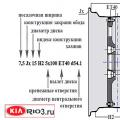
The private owner of the forum of electric mobility, Kurmanenko Gennady Viktorovich from the Dnepropetrovsk region, having summarized the information of the forum, has developed a scheme for a set-top box for a pulsating battery charge. The device can not only charge the battery with current pulses, but also control the voltage on the battery, and when the set level is reached, turn on a pulsating add-on with the possibility of desulfation.
Please note that the set-top box is connected between the charger and the battery. In this case, the wires from the set-top box to the battery should be no thinner than the wires from the charger to the set-top box, and preferably shorter. Otherwise, the ripple of the charger will interfere with normal work prefixes.
Fig. 2 Printed board
WITH once you should warn: The charger to which this set-top box will be connected must withstand the impulse load mode. Perhaps some electronic chargers will become depressed from this load behavior, they also expected to have a calm and predictable battery. And here, the battery is there, then it is not.
Gennady Viktorovich, being the operator of a defectoscopic installation for checking rails, uses an attachment for high-quality charging of batteries and restoring those that have lost their performance. Earlier, the simplest chargers, popularly nicknamed "boilers", were used to charge the batteries.
We proceed to describe the operation of the device circuit.
From the wire marked "+" through the diode VD1, power is supplied to the parametric (linear) power stabilizer consisting of a resistor R1, a capacitor C2, a Zener diode VD3 (for example, KS191).
Why through a diode? The load has a pulsed nature, the diode performs the functions of decoupling the unstable battery from the control circuit.
From the point after the VD1 diode, we take the voltage to the analyzer (comparator) of the battery charge.
The comparator consists of the following elements: resistors R1-R3, R5-R7, capacitor, integral stabilizer TL431, transistor VT1.
On the basis of the transistor VT1, the VD2 stabilizer maintains a fixed voltage; at the emitter of this transistor, the voltage changes in proportion to the change in the voltage on the battery. When the voltage on the battery rises above that set by the resistor R1, the transistor VT1 closes and unlocks the previously inhibited blocking generator on the NE555 microcircuit.
A few words about the blocking generator: At the beginning of the charge, it is blocked by the voltage analyzer, namely, the open transistor VT1 shorted the capacitor C4 and the generator cannot work, and the output (3) is in a high state.
And now about the work of that part of the control circuit, which is called the pulsator.
On the basis of the NE555 microcircuit, a generator is implemented with a frequency set mainly by a capacitor C4, as well as resistors R8-R10, a capacitor VD4.
Switch S1 can switch pin 7 of the microcircuit either to resistor R8 or diode VD4, which changes the duty cycle of the generator. In other words, it changes the time of the charging pulse and the discharge pause (or the absorption pause).
The author has chosen the generator frequency of 0.7 Hz. In my opinion, this is not enough. You need at least 10 times less. For this, capacitor C4 should be increased to 100 microfarads.
From output 3 of the microcircuit, a signal of positive polarity enters the base of the transistor VT4, opens it and the battery is connected to the negative wire of the charger, and the battery starts charging. After the expiration of the set time, the control pulse is removed, the VT4 transistor closes. But at the same time, the transistor VT2 also closes, while the transistor VT3 opens, which connects the discharge resistor Rn. The process of discharging the battery through this resistor begins. The HL1 LED indicates the fact of the discharge.
Resistor R16 serves to ensure the flow of the opening current for the transistor VT3, otherwise it will not turn on.
Thus, it can be stated that the positive pulse of the NE555 (KR1006VI1) microcircuit provides a time interval for charging the battery, and the negative (pause) pulse provides a time interval for the battery discharge.
Now a little about the device of the microcircuit.
The timer includes two precision comparators of high (DA1) and low (DA2) levels, an asynchronous RS-flip-flop DD1, a powerful output stage on transistors VT1 and VT2, a discharge transistor VT3, a precision voltage divider R1R2R3. The resistances of the resistors R1-R3 are equal to each other.

The timer contains two main inputs: a trigger input (pin 2) and a threshold input (pin 6). At these inputs, the external voltages are compared with the reference values, which are l / 3Upit and 2 / 3Upit for the indicated inputs, respectively. If the voltage at the Unop (6) input is less than 2 / 3Upit, then a decrease in the voltage at the Unop (2) input to a value less than 1 / 3Upit will set the timer to a state when the output (pin 3) has a high voltage. In this case, the subsequent increase in the voltage at the input Uzap (2) to the value of 1 / 3Upit and above will not change the state of the timer. If you then increase the voltage at the output Uпop (6) to a value greater than 2/3 Usup, then the DD1 trigger will be triggered and the voltage will be set at the output of the timer (3) low level, which will persist for any subsequent voltage changes at the input Uпop (6). This mode of operation of the timer is usually used when building time relays waiting for multivibrators. In this case, the Unop input (6) is connected to one of the capacitor plates of the timing circuit, and the timer is started at the Uzap (2) input by applying a short pulse of negative polarity. If it is necessary to create a self-oscillating multivibrator, then both inputs are combined. Transistor VT3 (7) serves to discharge the timing capacitor. When a high voltage appears at pin 3 of the timer, this transistor opens and connects the capacitor plate to the common wire.
If the voltage at the triggering input does not exceed l / 3Upit, then an increase in the voltage at the Unop input above 2 / ZUpit will lead to a low voltage at the timer output, and a decrease in voltage at this input below 2 / ZUpit will set high voltage at the exit. Thus, in this case, the timer works like a conventional comparator and can be used in temperature control devices, automatic switching on lighting, etc.
If the voltage at the Unop input exceeds 2 / 3Upit, then the timer output will have a low voltage regardless of the voltage value at the Uzap input. In conclusion, it should be noted that the supply voltage of the timer can be in the range of 5 ... 15 V.
The maximum output current of the timer is 100 mA. This allows an electromagnetic relay to be used as a load. Pin 5 is used to control the value of the reference voltage, as well as for possible change in its value by connecting external resistors. For decreasing possible action noise, this input is usually connected to the common wire through a capacitor with a capacity of 0.01 ... 0.1 μF. The Uc6p input (pin 4) allows the output to be set to low voltage independently of the signals at the other inputs. To do this, a low voltage should be applied to pin 4. A subsequent increase in the voltage at this input to a high voltage leads to the setting at the output of the timer of the state that was before the low voltage was applied to input 4 (meaning that the timing circuit is not connected). If this input is not used, it should be connected to pin 8. In time relay circuits, the Ucr input is often used to reset the timer, corresponding to the closed transistor VT3.