Location of controls and instrumentation
Shown accordingly. All devices are located on a hinged plate in
Left side of the cockpit dashboard.
Steering wheel6 with a recessed hub, which improves the observation of the readings of the instrumentation.
Pedal2 hinged-type clutch release is fixed on a bracket under the dashboard, to the left of the steering column.
Pedal3 for operating the service brake valve and the pedal 4 for controlling the fuel supply are fixed in one bracket, which is installed on the cab floor, to the right of the steering column.
Button1 auxiliary brake control valve is located on the cab floor under the steering column. By pressing the button throttle, blocking the flow area in the exhaust gas pipeline, creates a back pressure in the exhaust system. At the same time, the fuel supply is cut off.
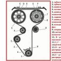
Figure: 8. Governing bodies:
1 - button of the auxiliary brake control valve; 2 - clutch release pedal; 3 - pedal for operating brake valve control; 4 - pedal for fuel supply control; 5 - air distributor; 6 - steering wheel; 7 - wiper blade; 8 - window regulator mechanism handle; 9 - mechanism lever remote control gearbox; 10 - door lock handle; 11 - handle of the longitudinal movement of the passenger seat; 12 - handle of the passenger seat backrest angle mechanism; 13 - handle of the seat suspension stiffness adjustment mechanism
Driver; 14 - the head of the engine stop lever cable; 15 - handle of the parking and spare brakes control valve; 16 - locking mechanism for adjusting the angle of inclination of the driver's seat back; 17 - cable head manual control fuel supply; 18 - lever for longitudinal movement of the driver's seat; 19 - fairing
Lever15 of the parking and spare brake control valve is located to the right of the driver's seat.
The handle is fixed in two extreme positions. When the crane handle is moved to the vertical position, the parking brake is applied. It turns off when you move the handle to a horizontal position. In any intermediate position (non-fixed) the emergency brake is applied.
Button 27 of the emergency release valve is located under the instrument panel, to the left of the steering column. Designed to turn off parking brake in case of emergency switching on at
Movement.
Lever arm 30 of the valve for activating the center differential locking mechanism is located under the instrument panel, to the right of the steering column, and has two fixed positions. The lock should be enabled when driving on slippery and muddy roads, as well as when driving off-road.
The handle 31 is located under the instrument panel and controls the blinds, which are closed when the handle is pulled.
Lever arm 9 of the remote control gearbox is located
to the right of the driver's seat. A switch for the divider control valve is mounted in the lever handle.
Head 17 of the cable for manual fuel control and the head 14 of the cable of the engine stop lever are located to the right of the driver's seat on the seal of the gear lever support.

Figure: 9. Governing bodies and instrumentation (except for KamAZ-5511):
1 - switches for checking the serviceability of control lamps; 2 - control lamp switching on an electric torch device; 3-4 - control lamps for turning on the direction indicators of the towing vehicle and the trailer; 5 - axle differential control; 6 - control lamp of the indicator of clogging of filter elements for oil purification; 7 - control lamp of pressure drop in the drive circuit brakes service brake of the front axle wheels; 8 - control lamp for pressure drop in the brake circuit of the working brake of the rear bogie wheels; 9 - control lamp of pressure drop in the brake drive circuit of the parking and spare brakes; 10 - control lamp of pressure drop in the circuit of the drive of the auxiliary brake mechanisms; 11 - control lamp for activating the parking brake; 12 - instrument panel; 13 - water temperature indicator; 14 - fuel level indicator; 15 - speedometer; 16 - tachometer; 17 - ammeter; 18 - oil pressure indicator; 19 - dashboard lighting regulator; 20 - manometer; 21 - ashtray; 22 - hinged fuse panel; 23 - glove box; 24 - electric torch switch; 25 - handle to control the heating tap and air distributor dampers; 26 - system switch alarm; 27 - button of the emergency release valve; 28 - handle of the control valve for the left wiper blade and windshield washer; 29 - handle of the control valve for the right wiper blade; 30 - lever of the valve for switching on the center differential locking mechanism; 31 - blinds control handle; 32 - switch lock for electrical equipment and starter; 32 - button for remote control of the switch rechargeable batteries; 34 - heater electric motor switch; 35 - switch for road train identification lights; 36 - fuel level indicator sensor switch (only for KamAZ-5410); 37 - switch fog lights; 38 - light switch; 39 - switch pre-heater 40 - pre-heater fuse.
Switch 28 PTO with safety button is located on the left side of the instrument panel. By turning the lever and simultaneous pressing the button turns on the drive oil pump dumping mechanism. At the same time, the signal lampbuilt into the switch button.
Switch lock 33 electrical and starter instruments are located under the dashboard to the right of the steering column.
When the key is turned to the right until it clicks, the electrical devices are turned on, and when the key is turned further, the starter is turned on.

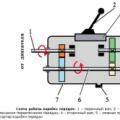
Figure: 10. Switch of the valve for divider control:
1 - case; 2 - switch; 3 - gear shift lever; 4 - cable.
Combination switch mounted on the steering column under the steering wheel and consists of switches for light and direction indicators and two switches for horns.
On the case of the combination switch, symbols of the switched-on electricity consumers are marked.
Switchlight is located on the right side of the combination switch and has a rotary handle 3, which is set in three fixed positions:
inclusion of sidelights, taillights and instrument lighting;
turning on the low beam;
inclusion high beam.
In addition, there is a non-fixed position of the handle for signaling with headlights.

Figure: 11. Controls and instrumentation of the vehicle - dump truck KamAZ - 5511;
1 - switches for checking the malfunction of the pilot lamps; 2 - control lamp for turning on the electric torch device; 3 - control lamp for turning on direction indicators; 4 - backup control lamps; 5 - control lamp for switching on the center differential locking mechanism; 6 - (left) - control lamp of the power take-off box: 6 - (right) control lamp of the indicator of clogging of filter elements for oil purification; 7 - control lamp of pressure drop in the brake drive circuit of the working brake of the front axle wheels; 8 - control lamp of pressure drop in the brake circuit of the working brake of the rear bogie wheels; 9 - control lamp for pressure drop in the brake drive circuit of the parking and spare brakes; 10 - control lamp of pressure drop in the circuit of the drive of the auxiliary brake mechanisms; 11 - control lamp for activating the parking brake; 12 - instrument panel; 13 - water temperature indicator; 14 - fuel level indicator; 15 - speedometer; 16 - tachometer; 17 - ammeter; 18 - oil pressure indicator; 19 - dashboard lighting regulator; 20 - manometer; 21 - ashtray; 22 - hinged fuse panel; 23 - glove box. 24 - electric torch switch; 25 - handle to control the heating tap and air distributor dampers; 26 - switch of the alarm system; 27 - button of the emergency release valve; 28 - power take-off switch;
29 - handle of the control valve for the left wiper blade and windshield washer; 30 - handle of the control valve for the right wiper blade; 31 - lever of the locking mechanism activation valve center differential; 32 - blinds control handle; 33 - lock switch for electrical equipment and starter; 34 - button for remote control of the battery switch; 35 - heater electric motor switch; 36 - switches and tipper device; 37 - light switch; 38 - fog lamp switch; 39 - pre-heater switch; 40 - pre-heater fuse.
Power buttonpneumatic sound signal 4 is located at the end of the light switch. The direction indicator switch lever 1 is located on the left side of the combination switch. Moving the lever forward turns on the right turn indicators, and when moving backward turns on the left turn indicators of the vehicle. The switch has automatic device, returning the lever to the neutral position after the end of the steering wheel rotation to the position corresponding straight motion car.
The electric horn is turned on when the direction indicator switch lever is moved up.
Button33 of the remote control battery switch is located on dashboard to the right of the instrument panel.
Switch24 electric torch device has a non-fixed position - turning on the device.

Figure: 12. Combined switch and the position of the light signaling switching elements:
I - inclusion of indicators of the left or right turn; II - turning on the sound signal; III - signaling with headlights; IV - inclusion side light; V - turning on the side light and dipped headlights; VI - turning on the side light and main beam headlights; 1 - lever; 2 - case; 3 - light switch handle; 4 - pneumatic horn button.
Crane control
Technically competent crane control ensures high performance and trouble-free operation. Excellent mastery of levers and other crane controls is one of the basic requirements for an operator. Underestimation of this issue, recklessness while working on a crane or, conversely, the manifestation of lethargy, sluggishness in management can easily lead to serious consequences and even accidents.
Crane control consists of the following elements: correct use of levers and other crane controls in accordance with the operations performed; maintenance of the control system in excellent condition; adjustment of the control system and especially clutches and brakes.
The location of the levers and other controls on the crane, the combination of switching on and off of individual levers when performing a particular operation depends on design features crane; usually these data are indicated in the passport of the crane and in the instructions for its operation.
When operating a crane using lever systems, two possible options should be kept in mind:
1) if the engine driving the power mechanisms of the crane has one direction of rotation (for example, a non-reversible steam engine), then each position of the lever will correspond to a well-defined operation performed by the crane;
2) if the engine is reversible and capable of changing the direction of its rotation, then there will be no such correspondence (for example, with the same position of the lever, the crane can rotate both to the right and to the left, depending on the direction of movement of the engine). Therefore, if, with a non-reversible engine, it is possible to quite accurately establish the order of switching on the control levers and their positions, then with a reversible engine, the most rational combination of the positions of the levers can only be recommended.
A non-reversible steam engine is installed on the PK-TSUMZ-15 steam valve, which allows you to accurately indicate the position of one or another lever or pedal when the crane performs certain operations. Table B 25 shows data on the positions of the crane control levers PK-TSUMZ-15.
Skillful crane control allows you to combine operations, that is, to perform several operations simultaneously. In this case, the position of the levers corresponds to their positions when performing each operation separately. It should be borne in mind that the simultaneous execution of a number of operations is either completely impossible, or adversely affects the crane mechanisms. For example, for some cranes, it is not allowed to change the boom reach with a load on weight, and even more so at the same time to perform any other operations, since in this case difficult conditions operation of the boom lifting mechanism, on the one hand, and on the other, it is easy to exceed the maximum permissible reach for the lifted load, which will disturb the stability of the crane.
It is also necessary to avoid, even on a horizontal section of the track, the simultaneous movement of the crane and its rotation if there is a load on the hook close to the maximum permissible for a given outreach. how general rule, it should be recommended to turn off all mechanisms that are not needed when performing a particular operation; braking means in these mechanisms are desirably activated.
In fig. 186 shows levers and pedals for controlling the PK-6 crane. This crane has a reversible steam engine as an engine, as a result of which recommendations on the order of switching on and off the control levers are given in the most general form.
Direction of rotation crankshaft steam engine is changed by the rocker control lever, and the middle position of this lever corresponds to the middle position of the rockers, at which the machine does not work.
The extreme positions of the rocker arm correspond to two opposite directions of rotation of the crankshaft.

Figure: 186. Levers and pedals for crane control PK-b:
1 - lever for engaging the load clutch; 2 - lever for engaging the clutch of the grab; 3 - lever for engaging the clutch of the main shaft; 4 - lever for turning clutch engagement; 5 - lever for engaging the travel clutch; b - lever for switching on the boom lifting clutch; 7 - turn brake pedal; 8 - movement brake pedal; 9 - load brake pedal
Table 25 

The position of the rocker lever "From itself" corresponds to forward motion steam engine, rotation of the crankshaft clockwise, and the position of the lever "towards itself" corresponds reverse steam engine.
The start and stop of the steam engine, as well as the regulation of the rotation speed of its crankshaft, are carried out by the steam regulator lever. The “Pull” position of the regulator lever corresponds to the closed position of the regulator, and the “Push” position corresponds to the opening of the regulator and steam access to the steam engine cylinders. In this case, the further the lever is deflected from itself, the more the regulator will be opened and the higher the number of revolutions of the crankshaft of the machine.
All crane lift mechanisms are operated by six levers and three foot pedals.
To perform certain operations with a PC crane. -6 it is recommended next order transfer of levers and parts from one position to another.
Lifting the load. To lift the load it is necessary to put the rocker lever in the "From yourself" position, and the levers of the load clutch and grab - to the "Towards" position.
Set the remaining levers to the positions at which the corresponding clutches will be disengaged. Disengage the gear of the grab drum.
The load is lifted by opening the regulator, while simultaneously pressing the load brake pedal. Lifting of the load stops when the regulator is closed and the load brake pedal is released. Both of these operations are performed at the same time.
The release of the load can be performed either on the brake When the load is up to 2 tons, or with a counter pair when the load is over 2 tons. In the first case, the load brake pedal is gently pressed, as a result of which the load is lowered by its own weight; In this case, the load clutch lever must be set to the "Push" position. In the second case, the regulator is opened slightly and the load, lowering under its own weight, is restrained by the steam engine; the position of the levers should be the same as when lifting the load.
Boom lift. To raise the boom, the boom clutch lever must be set forward (away from the boiler). The levers of the rocker and the main shaft can be in any, but the same position: if one is in the "From itself" position, then the other lever must also be in the "From itself" position.
To lower the boom, it is necessary to change the position of the rocker arm or the lever of the main shaft so that they both occupy opposite positions: if one is "Toward", then the other must be in the "Toward" position.
To move the crane it is necessary to set the boom clutch lever to the “Back” position (towards the boiler), while the position of the main shaft lever can be any. The position of the rocker lever for forward and backward movement should be checked with test runs and memorized.
The various positions of this lever depend on the position of the lower frame of the crane and will be constant until the crane turns on the turntable.
Turning the crane. To turn the crane to the right, the rotation lever and the rocker lever must be set to the same position: either both "Towards", or both "Towards the side". To turn to the left, these levers should be directed in different directions, if one is "Towards yourself", then the other is "From yourself".
When working with a grab, the following operations are possible: lifting the grab, opening the jaws, lowering the open grab, picking up the load, secondary lifting, turns, movement.
To perform these operations, use the rocker levers, grapple and load clutches, load brake pedal and adjuster lever. All other levers must be in positions corresponding to the disengaged clutches and the brakes.
The positions of the levers when performing operations with the grab are given in table. 26.
Table 26 
When performing the “Seize load” operation, it is necessary not to allow the supporting ropes to sag. To do this, as soon as the grapple jaws close, turn on the grab clutch by moving the lever to the "Toward" position.
If there is a jam and the grab does not open under its own weight, then it can be opened using a steam engine. To do this, the load clutch lever must be placed in the "Toward" position, the link lever must also be moved to the "Toward" position and smoothly open the steam regulator.
As you can see from the table. 26, grapple operations can be performed with one rocker arm position and only two levers and one pedal move, allowing all operations to be performed quickly one after the other, ensuring high productivity.
When working with a grab, just like with a hook, you have to turn and move the crane. Depending on whether it is necessary to turn or move the crane, the corresponding additional levers are connected, while most often the operations of lowering or lifting the grab are combined with turning the crane.
In fig. 187 shows the pneumatic control circuit power mechanisms crane KDV-15p.
All crane mechanisms are controlled from one operating panel by eight levers of the pneumatic system and two foot pedals that duplicate the pneumatic control of the brakes of the right and left drums. The presence of redundant drum brake control systems allows them to be controlled both by hand levers and by pedals, which is often more convenient, especially when working with a grab, when it is very important to have a gradual depressing and disengaging of the brakes.
Compressed air from the compressor installed on the engine, through an intermediate sump and oil-moisture separator, enters the receiver and, through the spools activated by the levers on the control panel, enters the desired pneumatic cylinder, activating one or another mechanism.
The vertical position of the levers on the control panel corresponds to the neutral (non-engaged) position of the clutches and the braked state of the brakes. Table 27 shows the positions of the levers and pedals when performing basic crane operations both when working with a hook and when working with a grab for handling bulk cargo.
Monitoring the technical condition of the pneumatic control system and maintaining it in proper working order are very important.
Pneumatic control along with clearly positive sides (ease of control, speed of response) has a number of easily vulnerable spots, malfunctions in which disrupt the operation of the entire system.
The following basic requirements are imposed on the pneumatic system: it must not pass air through rubber sealing rings and oil seals, from main pipes, in cylinders, spools and rotating joints; entering the line and cylinders compressed air must not be wet and must not contain oil, since the moisture in the air in winter time condenses and freezes in pipelines.
The presence of oil has a detrimental effect on rubber seals, it erodes them relatively quickly and reduces their durability. In order to prevent contamination and humidification of clean and dry air, it is necessary to carefully monitor the condition of the oil-moisture separator, more often drain condensate through drain valves, periodically flush and clean the oil-moisture separator from contamination. Good cooling air in the outdoor receiver protects the line from moisture condensation in it and largely protects it from freezing in winter.

Figure: 187. Pneumatic control of the KDV-15p crane:
1-lever to control the boom lifting mechanism; 2 - lever for controlling the clutches of the travel mechanism; 3 - left drum brake control lever; 4 - control lever of the left drum clutch; 5 - right drum clutch control lever; 6 - right drum brake control lever; 7 - lever for controlling the slewing mechanism clutches; 8 - swing brake control lever; 9 - control cylinder of the right drum clutch; 10 - control cylinder of the left drum clutch; 11- oil-moisture separator; 12 - sump; 13 - receiver; 14 - compressor; 15 - rotation clutch control cylinder; 16 - boom lift clutch control cylinder; 17 - control cylinder of the travel mechanism clutch; 18 and 19 - brake pedals; 20 - control panel; 21 - steering brake control cylinder; 22 - cylinders for controlling brakes of the right and left drums
Table 27 
In fig. 188 shows a control panel for a diesel-electric crane KDE-151.
The control of this crane is electric by means of a series of controllers, command controllers, contactors, relays, buttons and switches. Monitoring and control over the operation of the engine and all electrical equipment are carried out by instruments located also on the control panel. The engine is controlled by a button, when pressed, the starter is turned on to crank the engine when starting by the handle that controls the diesel fuel supply. To perform individual operations with the crane, it is necessary to turn it on and observe the following procedure for turning on the controls.
Self-propelled crane movement. The crane movement mechanism is activated by a handle. Moving it "Towards itself" or "From itself", it acts on the controller and, through the corresponding contactor, turns on the electric motors of the movement mechanisms, while the movement of the crane forward or backward is oriented according to the location of the crane chassis, that is, with one position of the handle, it is possible to move and boom forward, and the cab forward, depending on the position of the upper rotary part relative to the chassis.
The handle has five positions (positions) on each side of the neutral position. It is necessary to move from one position to another gradually as the crane accelerates, reaching maximum speed in the 5th position. At the same time, a long delay at intermediate positions can cause excessive overheating of the starting resistors. The movement of the crane is stopped by moving the handle to the middle, neutral position without delay at intermediate positions, while the brake of the mechanism remains open and you must press the pedal to brake.
Boom lance change. To change the reach of the boom by changing its tilt, the control panel has a push-button station with three buttons corresponding to the movement of the boom: "Up", "Down" and "Stop". By pressing the "Up" button, the mechanism is turned on to lift the boom, while the lift is automatically stopped when the boom reaches the upper limit position due to the triggering of the limit switch. For the lower position of the boom, there is no limiter on the crane, so when you press the "Down" button, you must monitor the amount of rope on the drum and stop lowering when 1.5-2 rope turns remain on the drum.
Turning the crane. The swing mechanism is activated by the handle, while the "Toward" handle transfer provides the crane to turn to the right, and the "Move" transfer - the left turn. The handle has five positions for each side. In the last, 5th position, the swing speed is the highest - 2.6 rpm. The swing mechanism has a centrifugal friction clutch, which ensures smooth operation of the mechanism. The handles should be turned on gradually from position to position, to avoid overheating of the ballasts again, it should not be delayed for a long time in intermediate positions. Braking of the mechanism is carried out automatically simultaneously with turning off the electric motor, while pressing the button you can leave the mechanism unbraked until the button is released.

Figure: 188. Crane control panel KDE-151:
1-emergency switch; 2- control handle for crane rotation; 3 - control button for the motor-generator group; 4 - handle for controlling the cargo drum (right); 5 - button to control the line contactor; b - the handle for controlling the fuel supply to the diesel engine; 7-button boom lift control station; 8- diesel starter start button; 9 - switch "transformer - accumulator"; 10 - handle for controlling the cargo drum (left); 11 - handle for controlling the movement of the crane; 12, 14, 16 - switches for lighting and heating; 13, 15, 17 - generator devices; 18, 20, 21, 22, 23 - diesel devices; 19. 24, 26 - switches for searchlights and signal lights; 25 - sound signal button; 27 - protection unit; 28 - cargo electromagnet control button; 29- right cargo drum release pedal; 30 - button for releasing the swing mechanism; 31- did not give a movement brake
Lifting and lowering the load. A feature of this crane is that it can lift the load with either of the two cargo drums or both at the same time, in the latter case, the lifting speed is twice as high.
The load lifting mechanism is controlled by the handle for the right drum and the handle for the left drum of the load. When these levers are moved to the "Toward" position, the mechanism is activated to lift the load, and by moving "Push" the rotation of the drums ensures the release of the load.
Both handles for each side have three positions, with the 3rd position corresponding to highest speed lifting.
When lifting a load, it is necessary to monitor the winding of the rope on the drums, avoiding excessive winding on one of the drums by unwinding from the other, for which lifting should be done alternately with each drum.
When lowering a load, especially loads over 10 tons, the engagement of the levers should be moved to the last position as quickly as possible, since the lowering speeds can be increased at intermediate positions.
When stopping the load on the weight, the handle should also be placed in the middle position, without stopping at intermediate positions. In addition, weights over 10 tons are recommended to be lowered alternately on two drums, preventing the development of high speed sinking. Forced lowering of the load from a low height can be performed by pressing the pedal when the load is lowered on the right drum without activating the mechanism.
Management when working with a grab. When working with a grab, the position of the handles and their switching sequence are as follows:
1. To lift a closed grapple, it is necessary to move the handles 4 and 10 "Towards you".
2. To open the grab by weight, you must put the handle 10 in the "From yourself" position, and all other handles must be in the neutral position.
3. To lower the open grab, put both handles 4 to 10 in the "Push" position.
4. The load is picked up by the grab when the handle 10 is moved to the "Toward" position and the pedal is pressed, which provides the support rope undercutting for better penetration of the grab into the bulk load.
The combination of these operations with the operations of turning or moving the crane is achieved additional control handles.
In case of emergency, in case of abnormal operation of any mechanism, it is necessary to use an emergency switch, when turned off, all power circuits are de-energized, after which all levers should be placed in neutral positions. Then you need to calmly understand the condition of the crane and, by turning on the button, take the crane out of the dangerous position.
The main requirement for lever control systems is the absence of backlash of the levers caused by increased slack-backlash in their joints.
To reduce backlash, it is necessary to systematically monitor the wear of the working surfaces in the hinge joints, to lubricate the working surfaces in a timely manner and well, avoiding their contamination.
It is not recommended to allow setting instead of rollers in the hinges of any other parts. Worn rollers must be replaced with new ones in time. The developed holes can be corrected with a sweep with a diameter of 1-2 mm larger than the holes themselves with the replacement of rollers or skillfully welded with electric welding followed by sweeping.
Each roller must be securely fastened with a check, pin or cotter pin; the fastening of the rollers by welding is in no case allowed.
Of great importance to normal work the levers have a state of locking devices. Latches and pawls of latches must act freely, without distortions and slack. The tabs of the latches, as well as the slots into which they fit, must have the correct shape. Poor fixation of the position of the levers can lead to spontaneous shutdown or activation of the lever and cause serious consequences. It is recommended that the surfaces of all hinges and latches be hardened.
Lever control systems are usually controlled by turnbuckles, mainly turnbuckles. Turnbuckles regulate the lengths of the rods in the system, after which they are secured using locknuts or other means, but so that they do not weaken during operation.
When electrical control crane, the excellent maintenance of the controls depends on the correct handling.
For trouble-free operation of electrical equipment, it is necessary to prevent its contamination and the ingress of oil and foreign objects into it. All equipment, depending on the installation scheme, must be protected either by separate protective covers, or be in closed cabinets.
The fixed contacts must be tightly clamped and reinforced immediately if they are loose. In case of burning, moving contacts should be promptly cleaned, refilled or replaced with new ones. In no case should you allow the contacts to be closed by foreign objects, the setting of various kinds of jumpers or the disconnection of faulty equipment from the system. If malfunctions are identified in one or another equipment, it must be repaired with the participation of an electrician.
Adjustment of crane control systems is mainly reduced to adjusting the clutches and brakes.
The cam clutch control system must be adjusted so that the middle position of the lever or engagement handle corresponds to the middle position of the clutch if it is two-way. When the lever or handle is moved to the extreme position, the clutch must move until it is fully engaged.
Control systems for friction clutches and brakes must be so adjusted by the turnbuckles in the levers or by the position of the pistons-plungers in the working cylinders (when hydraulic system), so that when the lever or control handle is turned on, a reliable tightening is achieved (adhesion of the friction surfaces), and when moving to turn off, a complete departure of the friction surfaces from each other is ensured. Depending on the design features of the friction clutches and brakes, the amount of retreat of the engaging surfaces is different, but on average it fluctuates within 1-2.5 mm. If at least partial contact of the friction surfaces occurs when the lever is off, this will cause friction and, as a result, overheating and wear of the clutch. Excessive heating of the clutches can be the result of insufficient force of pressing the friction surfaces against each other, as a result of which they can slip. In such cases, first check the clutch adjustment and then the entire control system.
Disk friction clutch crane PK-TSUMZ-15 (see Fig. 94) is adjusted as follows.
The fist is put in working position, equalize the uniformity of pressing the two-armed levers on it, for which the nuts are tightened or released. Having loosened the tie bolt and turning the adjusting nut, tighten it to failure, after which the fist is placed in the middle position, and the nut is additionally tightened by turning it by 50-70 °. Having installed the adjusting nut in this way, fix its position with a tightening bolt.
Brakes, both band and shoe, are usually adjusted by changing the amount of strips or pads moving away from the friction surfaces when the brake is released. The amount of waste should not be particularly large and most often is 1.5-2 mm. In closed-type brakes, in addition to the retreat of the pads or bands, the tightening force is also adjusted by tightening the brake operating spring or increasing the counterweight arm by moving it along the lever.
The clutches and brakes must be adjusted so that during work with a change in the size of the load being lifted, intermediate adjustments are not required, that is, so that the clutches and brakes work equally well both when lifting small loads and when lifting heavy loads.
TO Category: - Organization of railway cranes
DetailsLifting equipment is complex equipment that can be operated by a specialist with the appropriate knowledge. Crane operators undergo regular safety training and have appropriate work permits. Gantry cranes can be operated in several ways.

Gantry cranes can be controlled in several ways
Gantry Crane Control Options
The gantry crane is controlled by controllers and command devices. They are equipped with buttons or a joystick. The location of the entire system may vary. The driver must have the appropriate knowledge, since his task is to control several moments at once: the movement of the crane itself, the movement of goods up and down, as well as the movement of the cargo cart along the bridge.
In total, there are three types of control of lifting equipment, whether it is an overhead or gantry crane:
- from the control cabin;
- from the floor, using a wired control panel;
- from the floor, using a radio remote control.
Gantry Crane Cabin
The location of the controls in the driver's cab, which is fixed to the gantry crane bridge a, allows the equipment to be controlled directly from above, which gives full overview crane operator. As a rule, it is motionlessly located in such a place of the beam, from which the entire path of the freight carriage is clearly visible.
The operator's workplace in the control cab is equipped with a comfortable chair and a control panel, which contains all the necessary buttons or joysticks and levers. It also installs signaling systems that warn the crane operator about the occurrence of any unforeseen or dangerous situations: excess of the permissible weight of the load, emergency stop of mechanisms, etc.

The view from the control cabin should be maximized
The design of the control cabin is carried out individually for each piece of equipment, since this takes into account many features of the structure of the crane's metal structure and its technical data. Cabins are both closed and open.
Gantry crane: control from the floor
The floor control allows the operator to observe the moment when the load is picked up and lifted from a close distance. This type of control is especially convenient when the crane is designed in a non-standard design. Operating a gantry crane from the floor (ground) is safer for the operator than sitting in the cab.
Wired control panels for gantry cranes allow monitoring the movement of the load and the entire structure directly from below, from where the entire working cycle is clearly visible. Have of this type remotes have one drawback - the cable that runs from it to the crane body. This wire runs partially along the floor (or ground), which increases the risk of violating its integrity and, accordingly, can pose a threat to the life and health of personnel.
Radio control is modern systems control of the gantry crane operation to avoid possible problems with wiring. The device of such a system is quite simple: a signal receiver is installed on the crane body, and all control elements are located on the remote control. Any bridge or gantry crane can be converted to radio control.
Whichever method of gantry crane control is chosen, the crane operator must necessarily have the appropriate education, undergo safety training and a special medical examination. Before starting work, the serviceability of all gantry crane mechanisms must be checked.
Before starting work, a crane operator authorized to operate a crane must:
- familiarize yourself with the entries in the logbook;
- make acceptance of the crane;
- make sure that all mechanisms, metal structures, assemblies and other parts of the crane are in good working order, as well as the crane track.
The crane operator is obliged to receive a key stamp for operating the overhead crane in accordance with the procedure established at the enterprise from the crane operator who hand over the shift (from the person responsible for issuing the key stamps). If at the time of acceptance the crane is under repair, then the key stamp is accepted after the completion of the repair from the person responsible for the repair.
The crane operator is obliged to observe safety measures when entering the crane cab. If the entrance to the crane cabin is arranged through a bridge, then at magnetic cranes the trolleys supplying the electromagnet should not be disconnected when the door is opened in the end railings and should be fenced or located in a place inaccessible to contact;
The crane operator should inspect the crane mechanisms, their mountings and brakes, and undercarriage and anti-theft grips.
It is also necessary to check the presence and serviceability of the guards of the mechanisms and the presence of dielectric mats in the cab.
It is necessary to check the lubrication of the transmission, bearings and ropes, as well as the condition of the lubricating devices and oil seals, inspect the crane's metal structures, welded, riveted and bolted joints in accessible places.
The condition of the ropes and their fastening on drums and in other places is checked. Particular attention is paid to the correct laying of the ropes in the streams of blocks and drums.
Inspection of the hook, its fastening in the cage, the locking device on it is carried out (the same applies to another replaceable load-gripping body - the non-hook).
The presence of locks, devices and safety devices on the crane, the serviceability of the lighting of the crane and the working area is checked;
A thorough inspection of the gantry crane tracks and dead-end stops is necessary, as well as an inspection of electric motors in accessible places, trolleys (or flexible current supply cable), pantographs, control panel, protective grounding.
Attention should be paid to the fact that between the gantry crane and the piles of cargo and other structures along the entire length of the crane runway there must be at least 700 mm wide passages.
Together with the slinger, the crane operator must check the serviceability of removable lifting devices and containers, their compliance with the weight and nature of the cargo, the presence of stamps or tags on them indicating the carrying capacity, test date and number.
Inspection of the crane is carried out only with inoperative mechanisms and a disconnected switch in the crane operator's cab.
Inspection of the current supply cable is carried out with the disconnected switch, supplying voltage to the crane.
If additional lighting is required, a portable lamp with a voltage not exceeding 12 V can be used.
After inspecting the crane to test it, the crane operator must turn on the switch and the contact lock of the protective panel.
Before starting the crane into operation, the crane operator is obliged to empty all the crane mechanisms and check the correctness of the operation:
- crane mechanisms and electrical equipment;
- brakes for lifting and travel mechanisms;
- locks, signaling device, devices and safety devices available on the crane;
- zero blocking of magnetic controllers;
- emergency switch and contact lock with a key stamp.
In the event of an accident, the crane operator has discovered a malfunction (malfunction) that prevents safe work, and if it is impossible to eliminate them on his own, the crane operator is obliged, without starting work, to make an entry in the logbook and notify the person responsible for the safe performance of work by cranes and the engineer and technical worker responsible for maintaining the hoisting machines in good condition ...
It is prohibited to start work if:
- there are cracks or deformations in the metal structure of the crane, bolted or riveted joints are loose;
- the clamps for fastening the ropes are damaged or missing or their bolts are loose;
- the load rope has a number of wire breaks or wear that exceeds the standard established by the crane operating manual, as well as a broken strand or local damage;
- mechanisms for lifting load, moving a crane or trolley are defective;
- parts of brakes or crane mechanisms are damaged;
- the wear of the hook in the jaw exceeds 10% of the initial section height, the device that closes the jaw of the hook is faulty, the fastening of the hook in the cage is broken;
- faulty or missing locks, audible warning device, limit switches for lifting mechanisms, moving a crane or trolley;
- damaged rope blocks or pulley blocks;
- the load hook or blocks do not rotate;
- there are no fences for mechanisms or non-insulated live parts of electrical equipment, and grounding is missing or damaged;
- faulty crane tracks;
- damaged or missing anti-theft devices;
- the terms of technical examination, repair have expired, maintenance and preventive examination.
It is forbidden for the crane operator to correct malfunctions of electrical equipment, connect the crane to the power supply, replace fuses, connecting heating devices. In the event of such malfunctions, the crane operator must call an electrician.
In addition, the crane operator is obliged to check the presence of a certificate for the right to sling loads and a distinctive sign from the slinger who first starts working with him.
The crane operator does not have the right to start work if workers who do not have a slinger certificate are allocated for slinging goods.
The crane operator must ensure that there is sufficient illumination of the working platform in the crane range.
A corresponding entry is made on the acceptance of the crane in the logbook. After receiving the assignment and work permit from the person responsible for the safe operation of the cranes, the crane operator can start work.
OOO Kranstaloffers to significantly reduce the likelihood of emergency situations in production. We will provide the most complete range of services for the maintenance of lifting equipment of domestic and foreign production.
Produced by our certified specialists:
- checking the condition of the crane tracks (leveling the crane tracks);
scheduled inspections of the technical condition of hoists;
scheduled inspections of crane girders (bridge cranes), metal structures, etc.
will ensure your peace of mind and the safety of your employees at the facility.
Driving a crane truck is hard but interesting work. Those who have at least once seen the competitions of professional skill of drivers, probably admired the way professionals close a matchbox with a hook without crushing it. Each driver has his own experience, which he is unlikely to tell to uninitiated people. But the basics of working on a truck crane are useful and interesting to know even for those who simply hire equipment for loading and unloading or building a house.
During construction, truck cranes are usually used for "zero cycle" works, that is, when laying the foundation. Loading and unloading operations can be carried out either manually or using machinery. The first method is called manual, the second mechanized. The latter is mandatory for loads weighing over 50 kg, as well as when lifting loads to a height of more than 2 m.
Before starting work, the truck crane driver reads the construction and installation work project, if the crane is used in construction, or inspects the site where loading and unloading will take place. If there is a power line closer than 30 meters from the working site, the driver must obtain a permit for crane operation.
A truck crane is allowed for use, the resource of which has not yet been developed. The operation of decommissioned cranes is technically prohibited.
Before starting work, the driver inspects the crane that has not yet been started, checks technical condition mechanisms, readiness to work. Then the operator checks the serviceability of the mechanisms at idle speed.
The area where work takes place must be well lit. If there is heavy fog, snowfall within the working area, and the crane operator does not clearly distinguish between the load and the signals of the slinger, work stops until the weather conditions improve. The crane operator does the same during a thunderstorm or in strong winds.
In winter, the truck crane can only work at the permissible subzero temperature specified in its data sheet. For example, the KS-45717 truck crane can be used at temperatures from +40 to -40 degrees Celsius. Cranes also have humidity restrictions environment... Typically, at temperatures above 25 Celsius, humidity should be no more than 80%.
For work in more severe climatic conditions, for example, in the tropics or in the Far North, special models of truck cranes are produced.
The truck crane must be serviced by a team of at least 2 people - a driver and a slinger. Some firms assume that one person can be both. But technically, this is unacceptable, since the crane operator must be in the cab all the time, at the control panel. From there, he controls the situation.
A slinger is a person who secures loads for lifting. There are special devices for this - slings. All slingers are trained by profession, no one will take a person "from the street" to fix tons of bricks and metal. On the contrary, the more experience the slinger has, the better. Indeed, when securing various loads, sometimes you have to solve very intricate engineering problems!
A load weighing 5-10 tons can be secured by one slinger. It is physically unrealistic to sling cargo weighing 40-50 tons alone. In some cases (cargo weighing 80-100 tons, special climatic conditions etc.) may require three slingers or more. The load is secured only in a stable position, not in any way suspended or at an angle. If the weight of the load is unknown, it will only be lifted and moved after determining the actual weight.
Lifting, lowering, transferring the load, braking are performed smoothly, without jerking. During movement, the load must rise above the objects encountered on the way by at least half a meter.
Don't believe the stereotype “Construction is a place where accidents happen all the time”. Any risk technical work - shipbuilding, car repairs and even wiring in a residential building. Therefore, they all require compliance with safety precautions. What can not be done during the operation of a truck crane, we describe in detail in the corresponding article. And if you do not make gross mistakes, working with a truck crane will be just a technical process. Quite challenging - and just as exciting.