A cardan transmission with a constant velocity joint has found wide application in front-wheel drive cars to connect the differential and the drive wheel hub.
Cardan transmission of this type includes two equal joints angular velocitiesconnected by a drive shaft. The hinge closest to the gearbox (differential) is called the internal hinge, the opposite is the external hinge.
In order to reduce the noise level, the universal joint transmission with a constant velocity joint is also used in transmissions of cars with rear and all-wheel drive. In this case, the hinge of unequal angular velocities is inferior to a more perfect SHRUS design.
Cardan joint of constant angular velocities ensures the transmission of torque from the driving shaft to the driven shaft at a constant angular velocity, regardless of the angle of inclination of the shafts. The most common in the design of the transmission of a front-wheel drive vehicle is the constant-velocity ball joint.
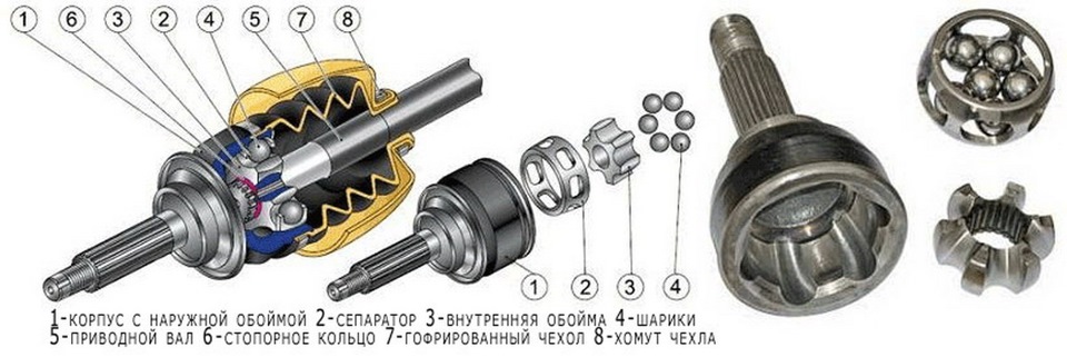
The constant velocity joint (abbreviated name - CV joint, everyday name - grenade) has the following device:
separator;
dirt cover.
Constant Velocity Joint Scheme
Housing has an internal spherical shape. Inside the case is located clip... There are grooves in the body and the cage, along which the balloons... This design provides a uniform transmission of torque from the driven shaft to the driving shaft at a variable angle. Separator holds the balls in a certain position. To protect the hinge from negative environmental factors (oxygen, water, dirt), the CV joint is installed dirt cover - "boot".
In the manufacture of a joint of equal angular velocities, a lubricant prepared on the basis of molybdenum disulfide is placed.
Cardan transmission with elastic semi-cardan joint
A semi-cardan elastic hinge ensures the transfer of torque between two shafts located at a slight angle due to deformation of the elastic link.
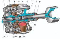
Diagram of a semi-cardan elastic hinge
A typical example of this type of swivel joint is elastic Guibo coupling (Guibo). The coupling is a pre-compressed hexagonal elastic element, on both sides of which the flanges of the driving and driven shafts are attached.
53) Main gear.
The final drive is used to increase the torque and change its direction at right angles to the longitudinal axis of the vehicle. For this purpose, the main gear is made of bevel gears. Depending on the number of gears, the main gears are divided into single bevel gears, consisting of one pair of gears, and double ones, consisting of a pair of bevel gears and a pair of cylindrical gears. Single bevel gears, in turn, are subdivided into simple and hypoid gears.
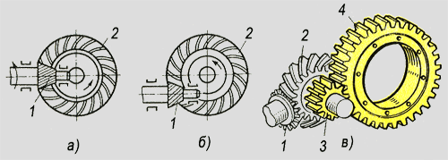
Types of main gear: 1 - leading bevel gear, 2 - driven bevel gear, 3 - driving cylindrical gear, 4 - driven cylindrical gear.
Single conical simple transfers (Fig. a) is used mainly on cars and trucks of light and medium carrying capacity. In these transmissions, the driving bevel gear 1 is connected to the cardan gear, and the driven gear 2 is connected to the differential box and through the differential mechanism with semi-axles. For most vehicles, single bevel gears have hypoid gears (fig. 6). Hypoid gears have a number of advantages over simple ones: they have the axle of the driving wheel located below the axle of the driven one, which allows the cardan gear to be lowered below, to lower the floor of the car body. This lowers the center of gravity and increases vehicle stability. In addition, the hypoid transmission has a thickened shape of the base of the gear teeth, which significantly increases their load capacity and wear resistance. But this circumstance determines the use of gears for lubrication special oil (hypoid), designed to work under conditions of transmission of large forces arising in contact between the teeth of the gears.
Double main gears (Fig. C) are installed on heavy vehicles to increase the overall gear ratio of the transmission and increase the transmitted torque. In this case, the final drive ratio is calculated as the product of the gear ratios of the conical (1, 2) and cylindrical (3, 4) pairs.
|
When the car is moving in bends and on uneven roads, the wheels of the drive axle travel a path of different lengths. To prevent tires from slipping on the road surface, the wheels must rotate at different speeds. Differential - a mechanism that allows the wheels of the driving axle to rotate at different speeds and the same (or different) torque supplied to them. In the transmission of vehicles with one driven axle, the differential is installed between the wheel drives (inter-wheel differential). In four-wheel drive vehicles, it can also be located between the driving axles (center differential). The traction force on the wheel depends on the radius of the wheel and the torque supplied to it. The product of the traction force and the dynamic radius of the wheel gives the torque that the differential must transmit to the wheels. When traction is weak or one wheel is suspended (unloaded), torque and traction at the wheel is very small or absent, the car will not be able to continue driving. This is a feature of the bevel gear differential, which is widely used in passenger cars. domestic cars... This type of differential is called symmetric because it distributes the torque equally between the wheels. This is because the satellite works as an equal-arm lever and transfers only equal forces to the axle gears and, accordingly, to the drive wheels. If one of the wheels has low grip on the road surface, then the effective torque on it is small, respectively, the symmetrical differential will supply the same force to the other wheel. That is, if one wheel slips, the traction force on the second is zero, which negatively affects the cross-country ability. To improve it, cars use full or partial differential locks, the degree of which is estimated by the locking coefficient. Locking factor (Kb) - the ratio of the torque on the lagging wheel to the moment on the leading wheel. Its value for a symmetrical differential is always equal to 1, for limited slip differentials from 1 to 5. The more KB, the better the vehicle's permeability. That is, with KB \u003d 3, the moment on the lagging wheel will be three times more than on the skidding wheel, and with KB \u003d 5 - five times. But the moment on the wheel at this second will be possible from 20 to 70%, depending on the possibility of the locking mechanism. |
55) Half shaftsThe axle shafts transmit torque from the differential axle gear to the drive wheel hub. Bending moments can be applied to the axle shaft from the vertical reaction to the action of gravity on the wheel, from the tangential reaction caused by traction and braking forces, and from the lateral force arising from skidding, as well as from the side wind. Semi-axles, depending on the design of the external support, which determines the degree of their loading by bending moments, are of two types - semi-unloaded and unloaded. By design, the axle shafts can have a flange at one end for bolting to the wheel hub, and on the other, a spline part that meshes with the differential half-axle gear. Another design provides a splined part at both ends of the axle shaft. On light trucks and cars, semi-unloaded axle shafts are usually used, in which the bearing is installed between the axle shaft and the casing at a certain distance from the median plane of the wheel. Due to this, bending moments are created on the shoulder (the plane of the outer part of the disc and bearing) acting on the semi-axle in the vertical and horizontal planes, in the vertical plane and (lateral reaction) on the shoulder equal to the wheel radius. On buses and trucks of medium and large carrying capacity, fully unloaded axle shafts are used. In this case, all bending moments are absorbed by bearings installed between the wheel hub and the axle housing, and the axle shaft transmits only torque. The axle shafts are subjected to significant loads during vehicle operation, especially when driving on the ground and on paved roads in poor condition. Therefore, special requirements are imposed on the axle shafts. Reducing stresses is achieved by increasing the radii of the transition between the axle shaft and the flange. The durability of wheel bearings is ensured by reliable protection against dirt ingress into them.
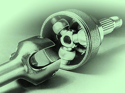
56) CV JOINT (abbreviated from constant-velocity joint), like the well-known universal joint, is designed to transfer rotation at an angle. CV joints are present in the design of cars with steerable drive wheels, and among motorists they are often called "grenades". The CV joint transmits uniform rotation and this differs from the usual "cardan", which has one unpleasant property: if input shaft bring a uniform rotation, then at the exit it will become intermittent, pulsating. Outwardly, all constant velocity joints look the same, but internal structure of CV joints for different machines is different. Each front wheel drive shaft has two joints. They provide the transmission of rotation at an angle and, in addition, compensate for the change in the length of the shaft during suspension operation, therefore, one of the joints must also have axial movement (as a rule, this is an internal CV joint). The outer CV joints of all domestic front-wheel drive vehicles are the same: a cage with six radial grooves is installed on the shaft. The body also has six radial grooves in which balls are placed that transmit torque from the shaft to the body and further to the wheel hub. This design allows only bending, so the internal hinges are made slightly differently and are designed for axial movement. In order to better represent the principle of operation of the CV joint, take a look at the picture.
Cardan drives with joints
equal angular velocities
The front drive wheels of all-wheel drive and front-wheel drive vehicles are simultaneously steerable, that is, they must turn, which requires the use of an articulated joint between the wheel and the semi-axle.
Cardan joints of unequal angular velocities transmit rotation cyclically and work acceptably only at small angles between the shafts, therefore they cannot meet the requirements for the uniformity of the transmitted rotational motion. In the drive of the driving steered wheels, the torque must be transmitted at a uniform speed to the wheels turning about the longitudinal axis of the vehicle at an angle 40…45
˚.
The fulfillment of such conditions can be ensured by cardan transmissions with hinges of equal angular speeds (SHRUS). They are sometimes called synchronous cardan transmissions.
A front-wheel drive vehicle typically uses two internal constant velocity joints that are kinematically connected to the gearbox and two external joints that are attached to the wheels. In everyday life, such hinges are usually called "grenades".
Until the middle of the last century, paired cardan joints of unequal angular velocities were often found in car designs. This design is called a double cardan joint. The double hinge was notable for loudness and increased wear needle bearingssince at straight motion the car, the bearing needles did not rotate and the lines of their contact with the cage and crosspiece were exposed to significant contact stresses, which led to wear and even flattening of the needles.
Currently, such bearings are rare in automobile designs.
The equality of the angular velocities of the driving and driven shafts will be observed only if the points of contact in the joint, through which the circumferential forces intersect, are in the bisector plane dividing the angle between the shafts in half. All CV joints are based on this principle.
Ball joints of constant angular velocity
Ball universal joints of equal angular velocities have received the greatest application. Among them, most often in the designs of domestic cars can be found weiss-type hinges with dividing grooves.
This design was patented in 1923 by the German inventor Karl Weiss. Weiss hinges are widely used in collapsible and non-collapsible versions on domestic cars of the brands "UAZ", "GAZ", "ZIL", "MAZ" and some others. Articulated joints of the "Weiss" type are technologically advanced and cheap to manufacture, they allow obtaining an angle between the shafts up to 32
°, however, their service life is limited 30 ... 40 thousand km mileage due to high contact voltages during operation.
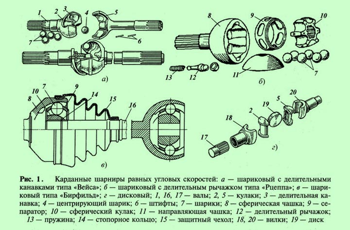
Dismountable hinge ( fig. 1) is structured as follows. Shafts 1
executed with the fists 2
and 5
in which four grooves are cut 3
... When assembled, the fists are located in perpendicular planes, and between them in grooves 3
four balls are installed 7
.
To center the fists, a pin is installed in the hole made in one of them. 6
with centering ball 4
... From axial movement, the pin is fixed by another pin 6
located radially.
Center lines of grooves 3
cut so that the balls 7
, transmitting forces are located in the bisector (bisectorial) plane between the shafts. Only two balls are involved in the transmission of force, which creates high contact stresses and shortens the life of the joint. The other two balls transmit torque when the vehicle is reversing.
In other designs, contact stresses are reduced by increasing the number of balls simultaneously participating in the operation, which inevitably leads to complication of the hinges.
Details ball joint "Rceppa" (fig. 1, b) are located in the cup 8
, which in the inside has six spherical grooves for the installation of six balls 7
... The spherical fist has the same grooves. 10
, in the splined hole of which the drive shaft of the cardan transmission enters. The balls in one bisector plane are set by a dividing device consisting of a separator 9
, cup guide 11
and indexing lever 12
.
The lever has three spherical surfaces: the end surfaces enter the seats of the driving and driven shafts, and the middle one - into the hole of the guide cup 11
... The lever is pressed against the drive shaft by a spring 13
... The lengths of the arms of the lever are such that when the moment is transmitted at an angle, it turns the guide cup 11
and separator 9
so that all six balls 7
are installed in the bisector plane and they all perceive and transmit efforts. This allows you to reduce dimensions hinge and increase its service life.
The hinge of the "Rceppa" type is technologically complex, however, it is more compact than the hinge with pitch grooves, and can work at angles between shafts up to 40 °. Since the force in this joint is transmitted by all six balls, it provides a high torque transmission in a small size. The durability of the "Rceppa" hinge reaches 100-200 thousand km.
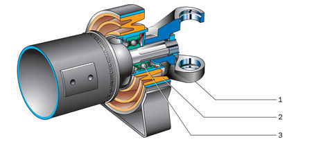
Another ball gimbal bearfield hinge presented at figure 1, c... It consists of a cup 8
, spherical fist 10
and six balls 7
placed in a separator 9
... Spherical fist 10
fits over the splined part of the drive shaft 16
and is locked with a ring 14
... The hinge is protected from dirt from entering the inner cavity with a protective rubber cover 15
.
All spherical surfaces of the hinge parts are made along different radii, and the grooves have a variable depth. Due to this, when one of the shafts is tilted, the balls are pushed out of the middle position and set in the bisector plane, which ensures synchronous rotation of the shafts.
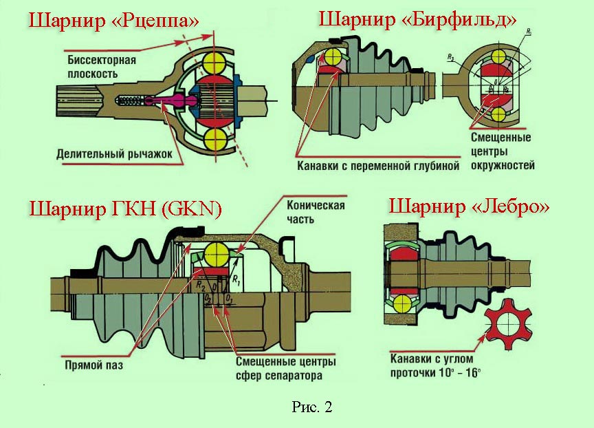
Bearfield-type hinges are highly efficient, durable, and can operate at angles up to 45
˚. Therefore, they are widely used in the drive of the steered wheels of many front-wheel drive passenger cars as an external hinge, or, as it is also called, an external "grenade".
The main reason for the premature failure of the hinge is damage to the elastic protective cover. For this reason, cars high cross-country ability often have a steel cap seal. However, this leads to an increase in the dimensions of the joint and limits the angle between the shafts to 40
°.
When using a Bearfield type hinge, a constant velocity hinge must be installed on the inner end of the driveline to compensate for the change in length cardan shaft during deformation of the elastic suspension element.
Such functions are combined in a universal six-ball gimbal hinge type "ГКН" (GKN).
Axial movement in GKN type hinges is provided by the movement of balls along the longitudinal grooves of the body, while the required amount of movement determines the length of the working surface, which affects the dimensions of the hinge. The maximum permissible angle of inclination of the shaft in this design is limited 20
°.
During axial movements, the balls do not roll, but slide in the grooves, which reduces the efficiency of the hinge.
In the designs of modern passenger cars, sometimes there are cardan joints of the "Lebro" type (Loebro), which, like the GKN joints, are usually installed at the inner end of the driveshaft, since they are able to compensate for the change in the length of the driveshaft.
Lebro hinges differ from GKN hinges in that the grooves in the cup and knuckle are cut at an angle 15-16
° to the generatrix of the cylinder, and the geometry of the cage is correct - without cones and with parallel outer and inner sides.
Such a hinge has smaller dimensions than other six-ball hinges, in addition, its cage is less loaded, since it does not perform the function of moving the balls in the fists.
The basic structure of these ball joints is shown in figure 2.
Front wheel drive of the VAZ-2110
Front wheel drive of a VAZ-2110 ( fig. 3) consists of a shaft 3 and two cardan joints 1 and 4 equal angular velocities. Shaft 3 the right wheel drive is made of a pipe, and the left wheel is made of a bar. In addition, the shafts are of different lengths. A protective cover is put on the shaft 6 , and then the assembled hinge with lubricant fixed against axial movement by a retaining ring 5 . Protective covers fastened with clamps 2 .
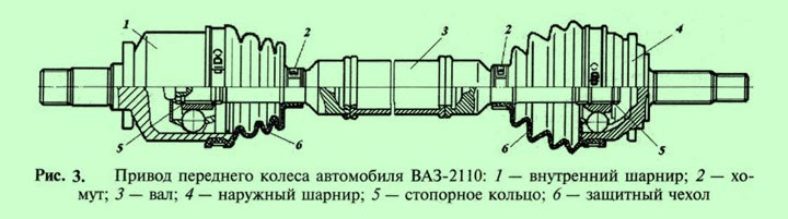
Internal hinge (internal "grenade) 1 , which is knitted with a differential, is universal, that is, in addition to ensuring uniform rotation of the shafts at a varying angle, it allows you to increase the total length of the drive, which is necessary to move the front suspension and power unit... This happens because the inner surface of the hinge housing 1 has a cylindrical shape, and the grooves in it are cut longitudinally, this allows internal details of the hinge to move along the longitudinal grooves in the axial direction.
Cam joints of constant angular velocity
On vehicles of medium and large carrying capacity of the brands "KamAZ", "Ural", "KrAZ" cardan drives in the drive of the front wheels operate under high torque. Ball joints cannot transmit large torques due to the occurrence of significant contact stresses and restrictions on the specific pressure of the balls on the grooves. Therefore, they use cam cardan joints ( fig. 1, g). Similar hinges are sometimes installed on UAZ front-wheel drive vehicles.
Cam gimbal equal angular velocities ( fig. 1, g) consists of two forks 18
and 20
that are inserted into fists 2
and 5
with grooves; the disc is included in these slots 19
... When transmitting torque and rotation from the drive shaft 17
on the driven shaft when the wheel is turned, each of the fists 2
and 5
rotates simultaneously relative to the axis of the fork groove in the horizontal plane and relative to the disc 19
in the vertical plane.
The axes of the forks' grooves lie in one plane that passes through the median plane of the disc. These axes are located at equal distances from the point of intersection of the axes of the shafts and are always perpendicular to the axes of the shafts, therefore the point of their intersection is always located in the bisector plane.
Such a universal joint requires increased attention to lubrication, since sliding friction is characteristic of its parts, which causes significant heating and wear of the rubbing surfaces. Sliding friction between the contacting surfaces results in the cam joint having the lowest efficiency of all constant velocity joints. However, it is capable of transmitting significant torque.
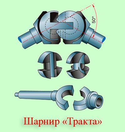
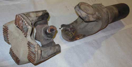
Another type of cam hinge of equal angular velocities is the Tract hinge ( on the picture), consisting of four stamped parts: two bushings and two shaped fists, the rubbing surfaces of which are subjected to grinding.
If we divide the cam gimbal along the axis of symmetry, then each part will be a gimbal of unequal angular velocities with fixed swing axes. In such a design, significant sliding friction forces also arise, which reduce the efficiency of the hinge.
Three-pin constant velocity joints
In a three-stud joint ( on the picture) torque from the drive shaft is transmitted by three spherical rollers, which are mounted on radial studs rigidly connected to the driven shaft hinge housing. Spikes are angled relative to each other 120 ˚. Spherical rollers are most often mounted on the studs using needle bearings.
The drive shaft has a three-roll fork with rollers in the cylindrical grooves. When the torque is transmitted between the non-aligned shafts, the rollers slide along the grooves and simultaneously slide in the radial direction relative to the studs. The limiting angle between the axes of the shafts up to 40 ˚.
A feature of the three-stud joint is that, unlike ball joints, the transfer of moment from the driving elements to the driven ones occurs not in the bisector plane, but in the plane passing through the axes of the studs. The equality of the rotational speeds of the driving and driven shafts is ensured for any mutual arrangement of their axes.
Cardan joint is consideredthe main unit for the power section, which is part of the propeller shaft. This hinge is supplied absolutely with any modification, while providing a torque of fifty, one hundred sixty, two hundred fifty, four hundred, six hundred thirty, and one thousand N m to agricultural vehicles, as well as to vehicles with a special purpose.
For agricultural vehicles cardan joint fully ensures its transmission at torque at such a number of revolutions per minute as one thousand two hundred and fifty. The working angular tilt is up to twenty two degrees. If there is a desire to receive more detailed and accurate information about these values, this can be found in accordance with GOST 13758-89.
Cardan joint provides security in torque relative to shafts whose axes intersect directly at an angle. Cardan joints are distinguished by angular speeds: equal and unequal. Equal Velocity Joints Depending on their design, they are subdivided into: ball plan, with dividing grooves, cam and double plan, and ball plan with a special dividing lever. Hinges with unequal angular velocity are either elastic or rigid.
Cardan joints with elastic plan give their effect relative to the axes and shafts, which intersect at an angle of two and three degrees, or slightly more. From deformation of an elastic nature on the connecting elements, they begin to perform functions with an additional damper in torsional vibration.
Cardan joints with rigid plan uneven speeds give their torque first to one shaft, and then to another. This happens directly through rather flexible joints in rigid parts. Such hinge there are two forksthat have cylindrical holes. They contain the ends of the connecting elements, which are called crosses. The two forks fit quite tightly on the shafts. When the shafts rotate, some of the ends at the spider begin to wiggle on a plane that is perpendicular to the axis on the shaft.
Cross-plan cardan jointsare used solely to ensure that the mechanical connection between the crankshaft and the main drive axle is fairly strong, good and flexible. The connection should be flexible, first of all, because in this case there is a constant movement in the area of \u200b\u200bthe leading part of the axle in relation to the car body vehicle at the moment when it is in its motion. The composition of such a universal joint next: a cross, consisting of four studs, cups, oil seals, needle bearings and circlips. Basically, such hinges serve for a very long time, sometimes they can even outlast the car itself, but it is worth considering that bad roads very adversely affect the cross-shaped hinge, where the body height can often change in relation to the road, where significant loads of a variable nature occur. Thus, in such conditions, the functioning of the hinge deteriorates sharply and this can lead to its failure. For such unfavorable conditions, there is a durable type of cardan shaft, which is equipped with double cross cardan joints. With such cardan jointthis problem has no definite meaning.
Cardan transmission
:
1 - elastic coupling;
2 - fastening bolt elastic coupling to the flange;
3 - crosspiece;
4 - oil seal;
5 - retaining ring;
6 - crosspiece bearing;
7 - nut;
8 - elastic coupling flange;
9 - oil seal;
10 - oil seal holder;
11 - safety bracket;
12 - bolt for fastening the bracket to the intermediate support;
13 - front cardan shaft;
14 - bracket for intermediate support;
15 - intermediate support;
16 - fork of the front propeller shaft;
17 - rear propeller shaft;
18 - fork of the rear propeller shaft;
19 - flange of the main gear drive gear;
20 - nut;
21 - the bolt of the fork
In car transmissions, cardan drives are used to transfer moments between shafts, the axes of which do not lie on one straight line and change their position in space. In general, the cardan transmission consists of cardan shafts, cardan joints, intermediate supports and connecting devices.
By arrangement, cardan drives are classified into closed and open.
Closed cardan transmission placed inside the pipe. The tube can absorb the forces and reactions occurring on the drive axle and serve as a suspension guide. In such a cardan transmission, only one joint is used, and the uneven rotation of the cardan shaft is compensated by its elasticity. Known designs in which the role of the cardan shaft is performed by a torsion bar (elastic shaft of small diameter), while there are no cardan joints.
Intermediate support design:
1 - plug;
2 - elastic cushion;
3 - intermediate support bearing
Open transmission does not have a pipe, and the reactive moment is taken up by the springs or jet thrust... The cardan transmission must have at least two hinges and a compensating link, since the distance between the connected units changes during movement. On long-wheelbase cars, a cardan transmission is used, consisting of two shafts. This excludes the possibility of coincidence of the critical angular velocity of the shaft with the operational one. Reducing the length of the shaft increases its critical speed, which should be at least 1.5 times higher than the maximum possible during operation. Dual-shaft drive shaft design requires application intermediate support one of the shafts, the bearing of which is installed in an elastic ring to compensate for the possible axial movement of the power unit on the frame or body.
![]()
With all the variety of designs and by kinematic characteristics and permissible angles between the shafts, universal joints can be classified as shown in the table.
The universal joint of unequal angular velocities was invented in the 16th century. by the Italian mathematician Girolamo Cardano and originally found application for hanging lanterns in carriages. Later, the English scientist Robert Hooke gave a mathematical description of the kinematics of this mechanism.
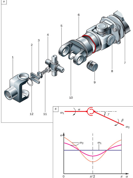
Details of the cardan transmission (a) and the graph of the dependence of angular speeds (b):
1 - slotted fork;
2 - U-shaped plate;
3 - lock washer;
4 - crosspiece;
5 - fork of the rear propeller shaft;
6 - rear propeller shaft;
7 - flange of the main gear drive gear;
8 - rear cardan joint;
9 - needle bearing;
10 - retaining ring;
11 - bolt; 12 - sealing ring;
α
- rotation angle of the drive shaft;
β
- angle of rotation of the driven shaft;
γ
- angle between shafts
Analysis of the cardan joint scheme shows that at a constant angular velocity of the drive shaft, the driven shaft rotates cyclically: in one revolution it lags twice and overtakes the drive shaft twice. In this case, with an increase in the angle γ between the shafts, the unevenness of rotation increases rapidly. In order for a cardan transmission with joints of unequal angular velocities to transmit synchronous rotation between the shafts of the connected units, it must consist of several joints, the mutual arrangement of which will compensate for the uneven transmission of rotation of each joint. For this reason, the minimum number of joints should be 2. At the same time, in a cardan transmission with two joints the following layout requirements must be met:
- leading forks are located at an angle of 90 ° to one another;
- the angles between the shafts in both joints γ1 and γ2 are equal to each other;
- all shafts lie in the same plane.
![]()
Universal joint of unequal angular velocities
For cardan gears having more than three unequal angular velocity joints, the synchronization of rotation of the shafts of the connected units is achieved by a certain ratio of the angles between the shafts of all joints, the ratio depending on the number of joints. The cardan joint of unequal angular velocities consists of two forks, into the cylindrical holes of which the ends of the cross are inserted. The forks are rigidly fixed to the shafts. When the shafts rotate, the ends of the crosspiece move relative to a plane perpendicular to the shaft axis.
The cross of the cardan joint must be strictly centered to eliminate variable imbalance of the cardan shaft during its rotation. Centering is achieved by precisely locating the bearing races with circlips or caps that attach to the pivot forks. The minimum angle between the shafts must be at least 2 °, otherwise the trunnions of the crosspieces are deformed by the needles and the hinge quickly collapses (phenomenon brinelling).
The development of the designs of cardan joints of unequal angular speeds followed the path of reducing losses associated with the rotation of the ends of the crosspiece in the holes of the forks. In the designs of the first hinges, the ends of the cross were mounted on plain bearings. Taking into account the fact that the number of hinges in the transmission of multi-axle vehicles can exceed two dozen, the use of plain bearings in them can significantly reduce the overall efficiency of the transmission. In cardan joints modern cars only needle roller bearings are used.
Previous designs used grease, which had to be periodically renewed through a special oiler. Cardan joints of modern cars are usually filled with high-quality grease, which is not replaced during assembly and operation.
There are already a large number of technical devices in mechanics that are capable of converting almost any amount of energy into a more convenient one for us or for others. technical devices... This article will discuss what a cardan transmission is, and what role does it play in the automotive industry?
What is a gimbal?
Cardan transmission is called a special mechanical device, designed to transfer torque between shafts that intersect in the center of the cardan. Main feature This kind of transmission is that the shafts have the ability to move angularly, which is very important for applications in many cars.
The cardan consists of two shafts with special forks at the ends. These forks are attached via axles to a common transmission center. Thus, with an angular change in position, the shafts can rotate freely, each in its own position.
Initially, the propeller shaft was installed on rear-wheel drive and four-wheel drive vehicles... It allowed from the gearbox crosspiece to the rear axle, as well as from the transfer case gearbox to front gear... The fact is that the back or front axle is attached to the vehicle's suspension, which is in constant motion. Thus, it turns out that changing the position of the bridge requires changing the position of the driven shaft. This is where the cardan shaft helps, which will not only transfer the required torque, but also act as an addition to the car's suspension.
The second mechanism in which the gimbal is also actively used is steering... Now, almost all cars have a so-called safe steering columnwhich folds quickly in the event of an accident and does not damage the driver's legs. All this is achieved through its ability to change the angular position at any angular position relative to another shaft.
Video - The principle of the cardan transmission
Why is the cardan shaft not used instead of CV joints?
It would seem quite a logical question. If the propeller shaft has this ability to rotate even when the angle of the shafts relative to each other changes, then why not use it in front-wheel drive cars?
Before answering this question, it is necessary to consider one of the significant disadvantages of this type of transfer. It consists in asynchronous rotation of one of the shafts. The fact is that if, for example, the drive shaft rotates at a uniform speed, then the driven one will necessarily rotate unevenly. In cars with front-wheel drive, the transmission of synchronous torque to the driving front wheels is the most important, therefore, more complex analogs of the universal joint - SHRUS are used there.
Nevertheless, in spite of this drawback, it can be concluded that it is easily eliminated if special paired joints are installed on each shaft, which will equal the synchronization of rotation, albeit not to absolutely, but at least approximately equal sizes.
SHRUS, however, is a type of cardan shaft and has a more complex design and another significant drawback - the impossibility of turning the wheels over an angle of 70 degrees. The hinge, on the other hand, is much better than a conventional universal joint, but it also has its drawbacks.
- Firstly, "grenades" have a lower service life than the gimbal and very often fail.
- Secondly, the reliability of fastening the hinge and cardan - here the cardan certainly wins, since it has a thicker all-metal structure.
In the process of working on rear wheel drive, the gimbal has the ability to create certain vibrations when driving on high revs... These disadvantages are reduced by using two cardan shafts at once. An increase in the number of gears leads to a smoother movement and when overcoming various uneven road surfaces.
All gearbox connections are lubricated transmission oil... In some gearboxes, such a shaft is inserted directly inside the gearbox, where this element is lubricated.
The crosspiece and propeller shaft are reinforced with needle bearings, which reduce friction when rotating and changing the angular position of one of the shafts.
Propeller shaft malfunctions
During the operation of the propeller shaft, you can observe a certain list of faults. The first kind can be attributed to various vibrations, which are caused by the bending and imbalance of the propeller shaft. Bent can be caused by sloppy and aggressive driving on uneven road surface... The second malfunction can be called knocks that appear in the process of cardan operation.
All these troubles have a detrimental effect not only on the condition of the propeller shaft, but also on the gearbox, as well as the gearbox. rear axle... In fact, the beating of the propeller shaft is a very dangerous phenomenon, because if the fasteners are completely worn out or a part breaks, the car will become completely immobilized.
Where else is the cardan drive used?
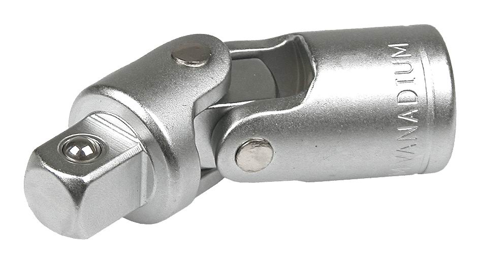
The cardan drive has found wide application not only in the automotive industry, but also in the instrumental part of any auto mechanic. So, for example, a special screwdriver attachment appeared, which has a cardan method for transmitting torque. Such a screwdriver helps to easily unscrew those nuts or bolts that are tightened in those places where it is problematic, and sometimes impossible, to get close with a regular tool.
This is perhaps all you need to know about the driveline. Care must be taken when handling such elements. The fact is that when any part of the cardan is changed or deformed, it starts to work unevenly, and, therefore, gradually wears out the gearbox and crosspiece rear gear... You can disassemble and assemble the driveshaft yourself, if you have minimum set tools and special equipment.