Maintenance of the steering consists in periodically monitoring the oil level in the hydraulic system; condition threaded connections steering gear, steering rods, sector mounts, bipod and swing arms; timely lubrication of the universal joint of the steering drive, flushing oil filter and oil change, check and adjustment freewheel steering wheel, as well as in the prompt elimination of malfunctions arising during operation.
Maintenance of the steering gear drive consists in periodically lubricating the universal joint, as well as checking the tightening of threaded connections.
To maintain a minimum level of vibration on the steering wheel, adjust the steering wheel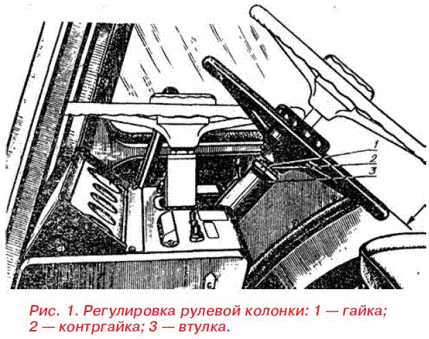 th column as follows:
a) tighten the round nut 1 (Fig. 1) until it touches the sleeve 3 so that the gaps in the joints are selected;
b) unscrew the nut 1 by 1.5 turns and lock with the lock nut 2.
Flushing the oil drain filter
Proceed as follows to flush the oil filter:
a) lift the cladding;
b) disconnect the oil lines, unscrew the bolts securing the cover to the body, remove the cover using two dismantling bolts;
c) unscrew pressure reducing valve and remove the drain filter;
d) wash the filter in a washing solution;
e) tighten the rotary shaft nut;
f) install the filter and perform the operations in the reverse order of disassembly;
g) at the same time adjust the axial play of the steering shaft, for which loosen the lock nut and screw adjusting bolt until it stops in the end of the shaft, then unscrew it by 1 / 8-1 / 10 of a turn and lock with a locknut. Before installing the filter in place, tighten the sector securing nut on the shaft and check the rack-sector gearing. If the gap between the teeth of the sector and the rack is more than 0.3 mm, the engagement should be adjusted. To do this, it is necessary to unscrew the four bolts of the rail stop - the ABD case and, removing the spacers in pairs, reduce the mesh in engagement to 0.1 - 0.3 mm. The filter is installed in reverse order.
Adjustment of engagement sector - worm.
The free wheeling of the steering wheel of a tractor standing on solid ground with the engine running should be no more than 30 °. If the specified value is exceeded, check and, if necessary, adjust the steering linkage joints. If this is not enough, you need to adjust the gap in the engagement sector - worm.
The procedure for adjusting the engagement sector - worm is as follows.
1. Using a jack, raise the front axle or disconnect the tie rods from the bipod.
2. Loosen the bolt, fastenings of the adjusting eccentric sleeve 20 (see Fig. 2) and turn it clockwise until the worm stops in the teeth of the sector. Then, with the engine running, turn steering wheel... If a sticking is felt in the worm-sector engagement, it is necessary to turn the sleeve counterclockwise until the jam disappears. The effort on the steering wheel should not exceed 15–25 N (1.5–2.5 kgf) with the rods detached from the bipod and 30–40 N (3–4 kgf) with the front axle jacked up.
3. Tighten the adjusting sleeve mounting bolt and connect the tie rods to the bipod and remove the front axle from the jack. 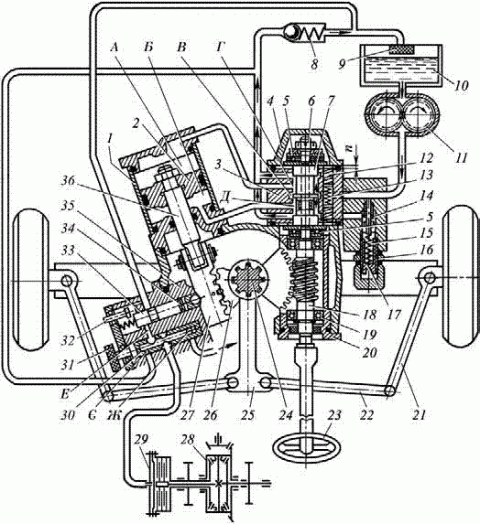
Figure: 2. Power steering diagram of the MTZ-80 tractor: 1 - power cylinder; 2 - piston; 3 - distributor body; 4 - cover; 5 - thrust bearing; 6 - nut; 7.33 - spools; 8 - pressure reducing valve; 9 - filter; 10 - oil tank; 11 - gear pump; 12 - slider; 13 - centering spring; 14 - safety valve; 15 - spring; 16 - lock nut; 17 - adjusting screw; 18 - worm; 19 - ball bearing; 20 - eccentric bushing; 21 - rotary lever; 22 - tie Rod; 23 - steering wheel; 24 - rotary shaft; 25 - bipod; 26 - sector; 27 - rail; 28 - differential; 29 - differential lock diaphragm; 30 - crane; 31 - handwheel; 32 - probe; 34 - pusher; 35 - emphasis; 36 - rod of the power cylinder; A, B - cavity of the power cylinder; B - middle injection coil; G, D - extreme drain grooves; E - sensor drain channel; Є - tap hole; F - throttle hole.
Tightening the worm nut.
A special spherical nut 1 (see Fig. 3) must press the bearing races against the ends of the spool. There is a gap between the spool and the bearing races due to wear, loosening or not correct tightening nut during installation can lead to an increase in free play of the steering wheel, and sometimes to unstable movement ("yaw") of the tractor, since in this case the spool can spontaneously move, directing the oil flow into one or another cavity of the hydraulic cylinder. Excessive tightening of the nut can cause spool skew and uneven turning torque.
To tighten the nut, it is necessary to unscrew the four bolts securing the distributor, remove the cover and fasten the distributor to the power steering housing with two diametrically located bolts, after placing washers under the bolt heads on 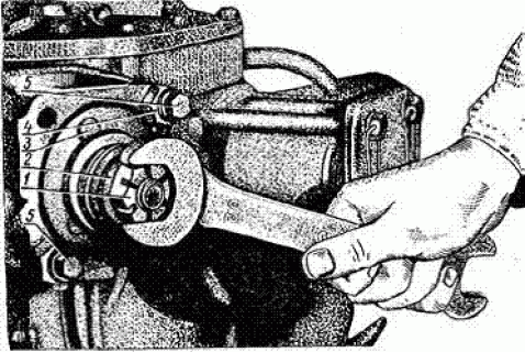 the thickness of the cover flange or a nut with a diameter larger than the bolt. Pull out the cotter pin and tighten nut 1 until the bearing races are firmly pressed against the spool. The tightening torque must be within 20 N × m (2 kgf × m).
Figure: 3 Installing the distributor body and tightening spherical worm nuts: 1 - spherical nut; 2 - washer; 3 - slider; 4 - assembly washers; 5 - bolts.
Then unscrew the nut 1 until the hole on the worm coincides with the nearest slot and pinch, install the O-ring and the cover and tighten the bolts. Remember that overtightening the nut increases the force on the steering wheel and can damage the thrust bearings. A sign of correct tightening of the nut is the absence of gaps between the spool and the bearing races and the return to the neutral position of the spool under the action of springs 13 (see Fig. 2) after stopping the rotation of the steering wheel.
Filling, level checking and oil change
Check the level, add oil according to the recommendations of the lubrication chart.
It is strictly forbidden to operate the tractor if the oil level is lower than the lower mark on the oil gauge 7 (Fig. 4).
When changing the oil, flush the filler filter. After changing the oil, start the diesel engine and turn the steering wheel from lock to lock several times, check the oil level again and, if necessary, add to the upper mark of the oil meter.
Differential lock control adjustment rear axle.
For normal work differential lock control correctly adjust the relative position of the handle 6 (Fig. 5) and valve 1 of the lock sensor, for which:
a) fix the free end of the cable 3 in the clamp with the screw 4, while the end of the cable should protrude beyond the clamp by 5-10 mm, no more;
b) set the handle 6 to position I. Pull the cable until the crane starts turning and fix the coupling with screws 4; bring the second retainer close to the coupling and secure it with a screw.
To check the correctness of adjustment, set the handle to position II, while the risk on the tap must match the “On” mark on the lock sensor cover. The handle and valve must return to position I from positions II and III under the action of a spring. 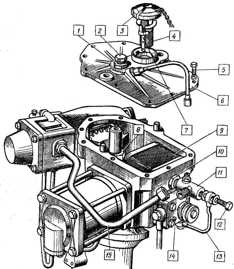
1, 10 - counter nutki;
2 - an adjusting bolt; 3 - filler neck cover;
4 - filter; 5, 12 - bolt; 6 - cover; 7 - oil meter; 8 - nut;
9 - drain filter; 11 - valve; 13 - valve oil line;
14 - probe; 15, 16 - oil pipelines.
Features of maintenance of hydrostatic steering.
During operation, after pouring a new portion of oil into the tank or air ingress into the hydraulic system of the HSU, bleed the system. To bleed, start the diesel engine and at low speed turn the steering wheel in both directions until it stops 2-3 times. Monitor the oil level in the oil tank.
The pins for installing the hydraulic cylinder of the HSU must be cotted. Oil lines and hoses must not touch each other and tractor units, except for the attachment points. Make sure that there is no oil leakage at the joints of the HPS hydraulic system parts. Lubricate the joints of the hydraulic cylinder periodically with lithol through oil cans.
ATTENTION! Disassembly and repair of the metering pump without the participation of a specialist from the plant or the manufacturer is prohibited. It is prohibited to tow the tractor when the diesel engine is not running. When turning the wheels to the extreme position, do not allow a prolonged delay of the steering wheel in the extreme position, as this causes overheating of the oil in the hydraulic system.
Avtodvor newspaper, September 2012
off. website http://avtodvor.com.ua
Safety, quality of work and driver fatigue largely depend on the state of the steering control of the MTZ-80, MTZ-82 tractor. therefore maintenance steering must be carried out especially carefully.
Maintenance of the MTZ-80, MTZ-82 steering consists in periodically monitoring the oil level in the power steering housing and replacing it, lubricating the steering drive universal joints, monitoring the condition of the threaded joints of the steering drive and steering rods, bipod and swing arms, securing the sector, checking and adjustable steering wheel free play.
The steering column of the MTZ-80, MTZ-82 tractor must be adjusted in order to exclude possible vibrations on the steering wheel. To do this, turn nut 12 by hand (see Fig. 1) to
the contact of the latter with the sleeve 10. In this case, the gaps in the joints must be selected, Then the nut 12 is turned off by one and a half turns and counter with the nut 13.
Figure: 1. Drive of the steering mechanism MTZ-80, MTZ-82
1 - splined bushing; 2 - front shaft; 3, 7 - cardan joints; 4 - intermediate support; 5 - middle shaft; 6 - rack; 8 - pin; 9, 12 - nuts; 10 - bushing; 11 - shock absorber; 13 - lock nut; 14 - steering wheel; 15 - handwheel; 16 - steering shaft; 17, 21 - screws; 18 - intermediate shaft; 19 - steering column pipe; 20 - earring; 22 - right side of the rack; 23 - retainer; 24 - spring; 25 - handle
The oil filter is washed in the following sequence:
Raise the cladding. Disconnect the oil supply line 12 (see Fig. 2) from the cover 11 of the pressure reducing valve 14. Remove the cover, for which first unscrew the two bolts securing it to the body 22, and then, using them as dismantlers, screw the bolts into the dismantling holes of the cover and remove her.
Disconnect the remaining oil lines from the pressure reducing valve 14. Holding the filter 13 by hand, unscrew the pressure reducing valve and remove the drain filter. Flush the filter in diesel fuel... To install the filter, operations are performed in the reverse order: The filter is washed at TO-3 (960-1000 operating hours). At the same time, tighten the nut 8 securing the sector on the rotary shaft.
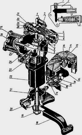
Figure: 2. Power steering power steering tractor MTZ-80 and MTZ-82
1 - cork; 2 valve cover; 3 valve adjusting screw; 4 worm; 5 - bolt of fastening of the adjusting sleeve; 6 - an adjusting sleeve; 7 - sector; 8 - nut; 9 - rail; ten -
adjusting bolt; 11 - top cover; 12 - nut; 13 - drain filter; 14 - pressure reducing valve; 15 - control valve for ABD; 16 - spool of differential lock sensor; 17 - control valve handwheel; 18 - bipod; 19 - bipod nut; 20 - drain plug; 21 - rotary shaft; 22 - case; 23 - rail stop; 24 - shims; 25 - stock; 26 - piston; 27 - front cylinder cover; 28 - thrust bearing; 29 - washer; 30 - spherical nut; 31 - spool
Power steering adjustment MTZ-80, MTZ-82
Check the worm-sector and sector-rail engagement, the tightening of the worm nut, the axial stroke of the pivot shaft, the safety valve, as well as the control of the differential lock valve. The "worm-sector" engagement and the tightening of the worm nut GUR MTZ-80, MTZ-82 are adjusted in the following sequence. Jack up the tractor so that the front wheels do not touch the ground.
Then loosen the tightening of the adjusting bolt 5, insert the key into the groove of the sleeve 6 and turn it clockwise until the teeth of the worm and the sector stop (while the bipod 18 should
be in the middle position). The sleeve is turned counterclockwise so that it turns 10-12 mm along the outer diameter. Tighten bolt 5. Start the engine and check the absence of jamming in the "worm-sector" engagement when turning the steering wheel in both directions until it stops.
If at the same time there are jamming, then it is necessary to increase the clearance in the engagement by loosening the bolt 5 and turning the bushing 6 additionally clockwise. The effort on the steering wheel should not exceed 30-40 N. Adjusting the tightening of the spherical nut 30 of the power steering worm MTZ-80, MTZ-82 consists in the correct tightening of the thrust ball bearings 28 to ensure that the ends of the spool 31 are normally compressed by the bearing rings.
From correct adjustments the correct operation of the power steering MTZ-80, MTZ-82 largely depends. Overtightening the nut 30 can cause the spool to skew and increase the turning force. The gaps between the bearings and the spool lead to an increase in the free travel of the steering wheel, as well as to wheel vibrations, since under these conditions the spool can move arbitrarily, changing the direction of the oil flow into one or the other cavity of the piston cylinder
Before tightening the nut 30, the four bolts of the distributor are unscrewed, the cover 29 is removed. The MTZ-80, MTZ-82 distributor is fastened with two diametrically located bolts to the power steering housing, placing a set of washers (or nut) under the bolt heads, the thickness (or height) of which is equal to the thickness cover flange 29. Tighten the nut with a torque of 20 Nm. In this case, the bearing rings 28 should be tightly pressed against the ends of the spool 31.
Then unscrew the nut 1 / 10-1 / 12 of a turn to match the slot in the nut for the cotter pin and the hole in the worm, and cotter the nut. Unscrew the two bolts screwed into the body,
cover 29 is installed in place and the distributor is fixed. The engagement "sector-rail" GUR MTZ-80, MTZ-82 is regulated by gaskets 24 under the flange of the stop 23 of the rail. In this case, the gap between the stop and the rail 9 should be 0.1-0.3 mm. Checking this gap, you need to squeeze rail 9 to sector 7.
The axial stroke of the rotary shaft of the MTZ-80, MTZ-82 tractor is adjusted in the following sequence: loosen the locknut tightening and screw the adjusting screw 10 all the way into the shaft end. Then turn out the bolt 10 pa 1 / 8-1 / 10 turn and counter it with a nut.
The safety valve is checked as follows. Instead of plug 1, a pressure gauge with a scale of division from 0 to
10 MPa. Start the engine and turn the steering wheel from one extreme position to another. At maximum speed crankshaft diesel engine, bring the oil temperature in the hydraulic system to 50 ± 5 ° C. In this case, the pressure should reach 8.8 MPa.
If the pressure gauge readings are less, increase the pressure to the required values \u200b\u200bby slowly screwing in screw 3. After adjustment, screw 3 must be locked with a nut and the cap must be installed.
A sign of a violation of the adjustment of the safety valve of the MTZ-80, MTZ-82 hydraulic booster is an increase in the effort on the steering wheel.
The free play of the steering wheel is checked in the parking lot with the engine running. Moreover, it should not exceed 20 °. If the free play of the steering wheel is greater, check
gaps in the joints of the steering drive MTZ-80, MTZ-82 and, if necessary, tighten the nuts securing the bipod and sector, fastening the swivel levers of the front axles and
steering rods hinges, tightening the worm nut, adjusting the worm-sector, sector-rail engagement and the axial stroke of the steering shaft of the power steering.
It is necessary to monitor the oil level in the steering hydraulic system of the MTZ80, MTZ-82 tractor. If the oil level is less than the lower mark on the oil gauge, it is strictly forbidden to work on the tractor. When changing the oil, wash the filler filter at the same time.
After changing the oil, the hydraulic system of the steering of the MTZ-80, MTZ-82 tractor is pumped in the following order:
Jack up the front axle until the front wheels lift off the ground. The engine is started and, at a low engine speed, the steering wheel is turned to
extreme positions 8-10 times (at first slowly, then quickly), without holding it in the extreme positions. Then check the oil level and top up if necessary
it to the upper mark of the oil gauge. The distributor has to be removed and reinstalled in case of replacement of its O-rings and flushing of parts.
When installing the MTZ-80, MTZ-82 distributor, do the following. Check the presence of O-rings at the ends of the distributor and the position of the spool 31 in its housing.
The spool must be installed so that its end with a chamfer on the outer diameter is directed to the power steering housing. Reverse installation of the spool will result in
a sharp increase in turning effort.
The distributor of the MTZ-80, MTZ-82 tractor is installed without an outer cover 29 and is attached to the body of the MTZ hydraulic booster with two diametrically located bolts,
placing a set of washers under the bolt heads, the thickness of which is equal to the height of the cover. Place a thrust bearing 28, a washer with a cone and tighten the spherical nut 30 in accordance with
with the recommendations above.
A sign of correct tightening of the nut is the absence of gaps between the spool and the bearing rings and the steering wheel recoil (return of the spool to the neutral position) after
stopping its rotation to the left.
Adjusting the power steering assumes following adjustments: worm-sector engagement, sector-rail engagement, worm nut tightening, axial stroke of the pivot shaft, safety valve, as well as control of the differential lock valve. To adjust the worm-sector engagement, loosen the bolt, insert the key into the groove of the sleeve flange, turn the sleeve clockwise (along the tractor's direction) until it stops at the middle position of the bipod, then turn counterclockwise 10-12 mm along the outer diameter of the flange. Tighten the bolt, start the engine, and check that there is no seizure when turning the steering wheel to both sides until it stops. If necessary, increase the meshing clearance by turning the bushing counterclockwise until it does not jam.
To adjust the sector-rail engagement, reduce the thickness of the set of shims under the stop flange until a clearance of 0.1—0.3 mm is obtained between the stop and the rail. When checking the gap, press the rail against the sector. The spherical worm nut tightens the thrust bearings. Correct tightening of the thrust bearings is essential for proper hydraulic booster operation.
Excessive tightening of the nut can cause spool skew and uneven turning torque. Before tightening the nut, fix the distributor with two bolts, first placing washers under the bolt heads to the thickness of the cover flange. Tighten the worm nut to a torque of 2 kgf / m (20N-m), unscrew it by 1/12 - 1/10 turn until the hole in the worm aligns with the slot for the nut cotter pin and cotter the nut. Unscrew the two bolts securing the distributor to the housing, install the cover and secure the distributor.
To adjust the axial travel of the pivot shaft, loosen the locknut, screw the adjusting bolt against the stop against the end of the shaft, then back it off by 1 / 8-1 / 10 of a turn and lock with the locknut. To adjust the safety valve, connect a pressure gauge with a scale of at least 100 kgf / cm2 (10 MPa) instead of a plug to the discharge line or to the valve cover. Turn the steering wheel all the way, let the engine maximum speed and turn the adjusting screw of the safety valve until the pressure gauge shows a pressure of 88 kgf / cm2 (8.8 MPa).
After adjusting the valve, secure the cap with wire. Perform the adjustment at an oil temperature of 50 ± 5 ° C. Check the free play of the steering wheel with the engine running while the tractor is parked. In this case, the free play should be no more than 20 °. With increased free travel, check the backlash in the steering drive connections, tighten the nuts securing the bipod, sector and pivot levers, adjust the steering linkage joints, check the tightening of the worm nut, worm-sector engagement, sector-rail and the axial travel of the power steering pivot shaft.
Adjust the control of the automatic differential lock valve in the following sequence:
a) turn the valve clockwise until it stops (to the “off” position) and fix it in this position;
b) fix the cable in the clamp with a screw;
c) tighten the cable with the clutch and fix it in this position with the screws, while the pin should reach in the groove of the guide forward until it stops, i.e. the handle is set in position;
d) release the tap from fixation;
e) set the handle to position II (set it to the middle position on the guide, turning it clockwise by 90 °); in this case, the valve under the action of the spring must turn to the "on" position. To check the correctness of adjustment, remove the handle from the groove of the guide by turning it 90 ° counterclockwise; in this case, the handle, under the action of the spring, should move forward as far as it will go, and the valve should turn to the off position.
Steering - these are units, mechanisms and devices combined into a system that provide a change in the direction of movement of the tractor.
In wheeled tractor models, the direction of movement of the machine is changed by turning the front steered wheels at different angles. When cornering, the front and rear wheelsets follow an arc around a common center located on the extension of the rear wheel axle.
The operation of the steering system is based on the interaction of the steering mechanism, which performs the function of transferring the control action from the operator's steering wheel with the steering mechanism, which converts the force transmitted to him into turning the wheels.
The direction control system for wheeled tractor vehicles includes:
- Installed on front axle steering link, formed by two bipod connected to each other transverse rods, the ends of which are in contact with the pivot levers;
- United cardan joints sequentially located steering, intermediate, middle and front shafts, transmitting the rotation of the steering wheel to the hydraulic booster;
- Fixed on the steering column located in the tube front shaft steering wheel with variable height and tilt;
- Steering column with mechanisms for tilting and changing the height of the steering wheel;
- Mounted in one housing located in front of the radiator, the steering gear and the hydraulic booster, which provides an intermediate hydraulic and mechanical connection of the operator's steering wheel with the tractor wheels;
- The hydraulic circuit supporting the operation of the hydraulic booster, which includes a gear-type pump, a working fluid distributor, a power cylinder and a sensor that issues a command to lock the rear axle differential;
- Steering gear, consisting of a worm, located in an eccentric bushing resting on two radial bearings; two-crown sector, which is in constant contact with the worm and the rail connected to the rod of the power cylinder; and fastened in the tail of the worm, spool;
- The rotary shaft and bipod transmitting the movement of the sector to the nodes of the steering trapezoid.
Hydraulic power steering
The hydraulic power steering (GUR) is a hydromechanical device designed for:
- reducing the level of the operator's physical efforts required to turn the tractor;
- improving the management of changing the direction of the tractor;
- reduction of shocks and vibrations on the steering wheel arising during the movement of the front wheels on unevenness.
The device becomes especially relevant with increased loads on the front wheels - while driving on high speed and when working with heavy attachments.
Power steering design
The main structural elements hydraulic booster device:
- A body serving as a container for working fluid and a base for fastening parts;
- Gear pump that circulates oil in the hydraulic circuit of the device;
- Sector constantly in contact with the worm of the steering mechanism, fixed on the pivot shaft;
- It has three pivot points, which transmits the rotary movement of the sector to a bipod attached to its end, connected to the transverse rods of the front wheels;
- A rail in contact with the sector, transmitting to it the translational movement of the cylinder piston through the rod connecting them;
- Fixed by three pairs of sliders, supported by springs, a spool attached to the end of the steering worm;
- Filter for cleaning the oil circulating in the hydraulic circuit;
- Safety valve limiting the pressure level of the working fluid in the hydraulic booster;
- Hydraulic automatic system of the rear axle differential blocking (ABD), which includes a sensor, a spool, a flywheel, a dipstick and a tap.
The scheme of the steering booster
The basic principle of operation of hydraulic power steering is to increase the hydraulic force with increasing resistance to turning the machine.
The resistance arising during the turning of the machine causes an axial displacement of the worm of the steering mechanism, under the action of which the springs of the sliders holding the valve spool are compressed.
When the resistance to maneuver exceeds the pre-compression force of all three springs, the spool changes its position and opens the access of the working fluid to one of the cavities of the power cylinder.
The oil supplied to the cylinder moves the piston, the force of which is transmitted through the rack connected to it to the toothed sector, which rotates the rotary shaft.
After the cessation of the effect of the resistance arising during the rotation, the springs are straightened and the spool is set to the neutral position, blocking the flow of the working fluid into the cylinder.
If the resistance arising during the maneuver does not exceed the pre-compression force of the springs, the turn is performed by the steering gear without connecting the hydraulic booster device.
The rear axle differential lock modes are controlled using a handle located at the operator's workplace connected by a cable to the ABD sensor tap.
When automatic mode The DBA works according to the following algorithm:
- When straight motion of the tractor, the rear differential is blocked by a hydraulic cylinder, into which oil from the hydraulic booster housing flows through the sensor spool.
- When the front wheels are turned by an angle exceeding 13 degrees, the rack connected to the spool changes its position, blocking the access of oil to the cylinder blocking differential. The interruption of the oil supply is accompanied by the drain of the oil in the cylinder cavity. As a result, the differential is released from blocking.
Power steering adjustment
Basic power steering settings:
- Adjustment of the mechanical contact of the worm with the gear sector. Adjustment is made with the front wheels raised above the ground. With a key inserted into the groove of the bushing, it is turned clockwise or against its movement, ensuring that the clutch clearance of the sector-worm gearing matches the side clearances of the worm with the bipod in the middle position.
- Rack-and-sector gearing adjustment. The engagement is set using gaskets installed under the rail stop flange, achieving a gap between the rail and the stop of 0.1-0.3 mm.
- Adjusting the tightening of the steering worm nut. The essence of this setting is to securely commit to correct position bearings pressing the ends of the spool.
- Adjusting the axial movement of the rotary shaft. Adjustment is made using an adjusting screw installed on the end surface of the shaft, with loosened locknuts. Having previously loosened the lock nut blocking unscrewing of the screw, the screw is tightened to the stop, and then released, turning by 1/10 or 1/8 of a turn.
- The safety valve is adjusted with the engine running using a pressure gauge installed instead of the plug located on the valve cover. The pressure of the oil heated to a temperature of 50 degrees at the maximum speed of rotation of the crankshaft of the engine of the machine should be 8.8 MPa. The oil pressure is adjusted with a special foot screw, which, after the end of the adjustment, is locked and closed with a special cap.
- Checking the steering wheel free play. It is monitored with the engine running and is adjusted by checking and setting the clearances of the steering system connections, as well as the attachments of the swing arms, bipod and other steering parts. Free movement of the steering wheel is considered normal if it does not exceed 20 degrees.
Hydrostatic steering (HSS)
Hydrostatic steering system is a set of components and assemblies that reduce the level of operator's physical efforts when changing the direction of the tractor.
The main difference between hydrostatic control and tractor direction control using a hydraulic booster is the absence of a mechanical connection between the drive and the steering mechanism.
In the HSS, the wheels are turned by a power cylinder (cylinders), the operation of which is provided by a metering pump controlled by a steering wheel.
The HSS provides reliable control of vehicles moving at speeds up to 50 km per hour.
Hydrostatic steering system device
The main structural elements of the hydrostatic motion control are:
- A dosing pump device with an axial piston type valve module connected by oil pipelines to the power cylinders of the steering column and rotary hydraulic mechanisms;
- Power cylinders installed on the front axle that rotate the wheels;
- Maintaining the pressure of the working fluid in the system;
- Hydraulic accumulator;
- Autonomous tank for storing working fluid;
- Pipelines, sealing elements and connectors.
The scheme of operation of the hydrostatic direction control system
When the tractor moves in a straight line, the spool of the pumping and dosing device blocks the access of the working fluid to the cavity of the rotary cylinder (cylinders).
Turning the steering wheel is accompanied by a displacement of the spool, which opens the supply of oil to the corresponding cavities of the power cylinder or power rotary cylinders in a volume proportional to the angular movement of the steering wheel.
When the feed pump is inoperative, the metering pump functions as a pump driven by the steering wheel.
Advantages and disadvantages of hydraulic booster and hydrostatic steering systems
The advantages of steering systems equipped with hydraulic boosters over mechanical ones are:
- Less response time to steering control;
- Absorption of shocks and vibrations arising during the movement of the machine;
- High efficiency when converting steering wheel rotation into steering wheel movement.
The advantages of the hydrostatic steering system over the power steering include:
- The level of operator's physical effort required to turn the tractor is lower in comparison with the hydraulic booster;
- No backlash when controlling the direction of movement of the machine;
- Low weight of the dosing pump device;
- Possibility of installing elements of the hydrostatic system in different parts of the tractor.
A common disadvantage of such hydraulic systems - the need to use high-quality materials and connectors that exclude leaks of working fluid.
Re-equipment of hydraulic booster control to hydrostatic
In recent years, there has been a steady increase in equipping tractor equipment with hydrostatic steering systems and the conversion of models from power steering to HPS.
The trend is explained by the advantages of hydrostatic control and the relative ease of modernization.
You can convert a power steering system to a hydrostatic control system using one of the vendor-supplied conversion kits.
Typically, a kit of parts includes:
- rotary hydraulic cylinder;
- right and left swing arms;
- metering pump;
- fittings;
- hoses designed for the transportation of working fluids under high pressure;
- tie Rod;
- connecting and fastening elements.
Many owners of tractor equipment, converting the hydraulic booster control system into a hydrostatic one, use the hydraulic booster housing as a reservoir for the working fluid.
Using this approach allows you to:
- Simplify the use of the rear wheel differential lock.
- Maintain the weight balance of the tractor.
- Refuse additional ballasts, the need for which arises when dismantling the hydraulic booster.
- Eliminate the ingress of oil when leaking from the metering pump into the ground. When using the power steering housing as a container for the working fluid, the oil flowing from the pumping and dosing device enters it.
Installing a metering pump instead of a hydraulic booster
One of the advantages of hydrostatic control is the ability to install a metering pump connected to the steering column and power cylinder with flexible pipelines in various parts of the machine.
Most often, the pump and metering device is installed on the power steering housing or on the valve cover of the cylinder head, using their fastening elements to fix the pump.
Simplified sequence of conversion of a tractor equipped with power steering to hydrostatic control (option with the use of a hydraulic booster as a reservoir for the hydraulic steering fluid):
- The steering gear worm and the power steering valve are dismantled.
- A dispenser pump is installed. The main condition for correct installation of the pump is the absence of axial and radial loads on the device, to exclude which a bearing adapter can be used to center the steering shaft.
- The steering shaft is connected to the roller of the metering pump, if necessary, the shaft is shortened.
- The power cylinder is mounted on the front axle using a special bracket.
- The cylinder rods are connected to the swivel arms of the wheels.
- The dosing pump is connected to the hydraulic cylinder by two pipelines, which, depending on the direction of rotation, supply oil under pressure to the left or right space of the cylinder.
- The intake and drain of the dispenser is connected to the corresponding outlets of the hydraulic booster used as a reservoir for oil.
Restoration of power steering
If it is necessary to restore the power steering:
- The metering pump is dismantled.
- The dismantled worm and hydraulic valve are installed in the hydraulic booster.
- The swing arms are disconnected from the power cylinder rods and connected to the tie rod ends.
Malfunctions of hydraulic booster and hydrostatic steering systems and their elimination
| The main malfunctions of the power steering system and options for their elimination | ||
| Malfunction and its symptoms | The cause of the problem | Elimination options |
| Turning the steering wheel is difficult and requires considerable physical effort. | Damage to the worm screw bearings, deformation of the rods. | Replace damaged parts. |
| Increased level of adhesion of the gear sector and the worm gear of the steering mechanism. | Adjust the engagement of the parts. | |
| Worm nut not tightened enough. | Tighten the nut. | |
| Insufficient hydraulic fluid level or leakage. | Check the oil level and bring it up to the specified technical requirements. | |
| Air penetration into the system. | Check the suction lines and eliminate leaks. | |
| Free movement of the steering wheel, significantly higher than usual. | Air accumulation in the pipeline network of the rotary cylinders, oil foaming during hydraulic operation. | Check the tightness of the pipelines and the sealing and connecting elements of the system. Seal air leaks, adjust or replace seals and connections. Bleed the steering system. |
| The main malfunctions of the hydrostatic steering system and options for their elimination | ||
| Malfunction and its symptoms | The cause of the problem | Elimination options |
| Difficulty turning the steering wheel. | The feed pump does not create the pressure required for the normal operation of the system. | Repair the pump or replace it with a new one. |
| Low oil level in storage tank. | Add oil to the tank. | |
| Seizure of the universal joint of the steering shaft with the drive shaft of the metering pump. | Eliminate jamming. | |
| When turning the steering wheel, there is no stop. | Low oil level in the system. | Add oil to the tank. |
| Rotation of the steering wheel when there is no operator force applied to it. | The spool of the pumping and metering device does not take a neutral position due to jamming of the cardan joint of the pump drive shaft with the steering shaft. | Eliminate jamming. |
| Mismatch between the direction of rotation of the steering wheel and change in the direction of travel of the tractor. | Incorrect commutation of the pump leads with the cavities of the power cylinder. | Re-connect the pump and power cylinder leads. |
Removal and disassembly of the steering mechanism.Remove the clamp head with the cover, the steering wheel, the bushing and the shock absorber from the steering column. Remove the steering shaft from the steering column. Disconnect and remove the skirt part (left, right, sides and rear wall) from the instrument panel. Lift the latch and place the speaker in a position that is convenient for disassembly. Disconnect and remove the steering column fork support bolt and steering column post from the bracket. Disconnect the cardan forks by separating and removing the crosspiece. Disconnect the plugs and remove them from intermediate shaft and racks. Check technical condition parts and replace if necessary. The free play of the steering wheel with the position of the front wheels corresponding to the straight travel of the tractor should be no more than 25º when the engine is running.
Replacing the hydraulic booster assembly.  With a volumetric efficiency of 0.8 or less, replace the power steering with a new or overhauled one. The procedure for removing the power steering was described in previous articles. The sequence of performing the main operations and the correct techniques for disassembling, assembling and adjusting the power steering are shown in Fig. 1 - 12. Before removing the power steering, drain working fluid and unscrew the nut of the pivot shaft 4 (fig. 1). When installing the power steering, check the tightness of all oil lines. If a leak is found, replace the oil line. Install the power steering assembly on the fit bushings of the front beam of the half-frame, install all previously removed units and parts on the tractor in the reverse order to disassembly. In this case, the steering rods must be installed with grease nipples backwards along the tractor. Perceptible axial play in ball joints and rods is not allowed. The nuts of the power steering oil pipe fittings must be tightened to failure.
Troubleshooting the power steering 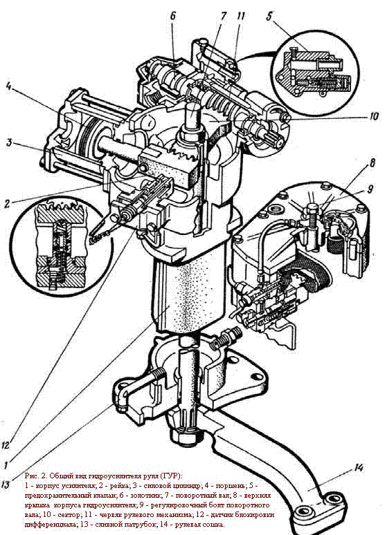 steering control.With an increase in the effort on the steering wheel more than 5 kgf, an increase in the free play of the steering wheel more than 20 ° (when the adjustment of the steering mechanism does not give the desired result), with a pressure drop limited by the safety valve below 75 kgf / cm2, with internal leaks of more than 3 liters / min, remove the power steering from the tractor, as indicated earlier, disassemble and check it, replace the parts that are not suitable for further operation. After removing the power steering, check the possibility of adjusting the worm-sector engagement. If, with the engagement adjusted in the extreme positions in the middle position, the play is more than 20 °, the worm and the sector should be replaced.
Disassembly. Remove the filler plug, take out the oil meter and filler filter; unscrew the nut and remove the bipod from the pivot shaft; unscrew the 1/2 fitting and the elbow from the bottom of the power steering housing. Unscrew the nuts and remove the oil return line, cylinder oil line, valve oil line and O-rings. Remove the bolts and disconnect the valve cover. Remove the o-rings, unscrew the cap from the safety valve adjusting screw, remove the o-ring, loosen the lock nut. Unscrew the adjusting screw, remove the gasket, take out the guide, spring and ball of the cover body. Turn out valve cover fitting, remove the O-ring from the fitting; unscrew the bolts securing the top cover. Screwing two bolts evenly into the mounting holes of the cover, remove it; at the same time, make sure that there are no distortions of the cover; unscrew the pressure reducing valve from the power steering housing; remove the drain filter. Unscrew the bolts and remove the blocking sensor 12 (Fig. 2), gaskets, rails; unscrew the plug from the lock sensor cover, remove the washer and take out the spring with the ball; remove the bolts and screw, remove the cover together with the tap. Remove the O-rings from the valve. Remove the spring from the spool hole, remove the O-ring; remove the spool from the rail stop; unscrew the bolts and remove the cover. Unscrew the bolts, turn the adjusting sleeve and take out the stub shaft 7 assembled with the sector 10. Unscrew the nuts and remove the sector and the supporting upper sleeve. Take out the worm 11 with bearings and distributor assembly; unpin and unscrew the nut on the worm shank. Remove the washer, thrust bearing, valve assembly with spool and sliders, remove another thrust bearing, washer and snap ring. Remove the sliders and springs from the body; remove the O-ring; remove the adjusting sleeve from the power steering housing; remove the O-ring and press out the seal. Remove the bolts and remove the cylinder; remove the locking ring from the finger, press out the finger and disconnect the rail 2 from the stem. Remove the front cover from the cylinder body, the O-ring, unscrew the nut, remove the piston 4 from the rod and the cover; remove O-rings and gaskets (replace if necessary). Press out the lower bushing from the power steering housing, remove the O-ring from the bushing. Place parts and assemblies in baskets or containers and rinse. Check the condition of the parts, if cracks are found, replace the parts. Check the spool and valve housing especially carefully; they can only be replaced as an assembly. Everything sealing parts replace with new ones.
Assembly.Assemble the power steering in the reverse order to disassembly. When assembling the power steering, special attention should be paid to the tightening torques of the nuts, the correct alignment of the pivot shaft, sector and rack marks, and the adjustment of the vertical movement of the pivot shaft. Do not cut or twist the rubber o-rings. Tightening torque of the rod nut 12kgf · m. When assembling the shaft with the sector, the marks on the parts to be assembled must be aligned. The tightening torque of the sector nut is 28-32 kgf · m. Before pressing the bearings onto the worm shaft, it is recommended to heat them in oil to a temperature of 90 ° C. To avoid damaging the lip of the cuffs, install them with tapered mandrels. Check shaft rotation. The shaft in the bushings must rotate without binding. When installing the blocking sensor, select the adjusting shims until a gap between the sector and the rail is 0.07-0.20mm, which corresponds to a gap of 0.1-0.3mm between the blocking sensor and the rail end when it engages with the sector without backlash. The number of shims on each side of the stop must be the same. Then fasten the locking sensor with the bolts. To adjust the gap in the worm-sector engagement, you need to turn the adjusting sleeve until a clearance of 0.03-0.08 mm is obtained in the engagement. This clearance corresponds to a worm play of 4 - 6 ° at a force of 1 + 05 kg · s on the steering wheel. When checking the backlash, the worm should not move in the axial direction. Turning the worm until it stops, you need to check its rotation, which should be light; jamming of the worm is not allowed. The spool must fit snugly into the body and move in it. The spool must be installed in the distributor body so that its chamfered end faces the hydraulic booster. Incorrect installation of the spool in the valve body leads to a sharp increase in the turning force. The steering gear worm nut is tightened with a torque of 2 kgf · m. If the holes in the worm do not coincide with the slot in the nut for the cotter pin, unscrew the nut 1 / 12-1 / 8 turn until the holes coincide and secure with a cotter pin. A sign of correct tightening of the nut is the absence of gaps between the spool and the bearing races and the steering wheel kickback (return of the spool to the neutral position) after stopping left rotation.