Send your good work in the knowledge base is simple. Use the form below
Students, graduate students, young scientists using the knowledge base in their studies and work will be very grateful to you.
Posted on http://www.allbest.ru/
- 1. Introduction
- 2. Technological part
- 2.1 Removing the unit from the machine
- 3. Design part
1. Introduction
1.1 Name of the unit, its place in the car
Steering the vehicle (Fig. 1) is equipped with a hydraulic booster 12, combined in one unit with a steering mechanism, a hydraulic booster control valve and an angular gearbox 13.
Figure: 1. Steering control: 1 - hydraulic booster control valve; 2 - radiator; 3 - cardan shaft; 4 - column; five - steering wheel, 6 - hydraulic system reservoir; 7 - power steering pump; 8 - pipeline high pressure; 9 - low pressure pipeline; 10 - bipod; 11 - longitudinal thrust; 12 - hydraulic booster with a steering mechanism; 13 - angular gearbox
Power steering reduces the amount of force required to steer the front wheels, mitigates impacts from uneven road surfaces, and improves driving safety by maintaining directional control in the event of a front tire burst.
overhaul power steering wheel
1.2 Working conditions, most typical malfunctions in operating conditions
Power steering malfunctions:
Parts of the steering gear, steering drive pivot joints, pivot joints cardan transmission steering, and wear of the slot in the connection of the steering shaft and the sliding fork of the universal joint, as well as the loosening of the fastenings of the steering mechanism, power steering, levers steering knuckles and steering arm. A sharp increase in the effort on the steering wheel required to turn the vehicle is usually due to faults in the hydraulic part of the steering. In particular, there may be air in pipelines and hydraulic devices, unscrewing the safety valve seat, or stuck bypass valve of the amplifier pump. There may also be oil leakage in the switchgear, the hydraulic booster, and a decrease in the performance of the booster pump.
Possible malfunctions GUR KAMAZ:
· Heavy turning of the steering wheel when turning to the left or right side;
· Heavy turning of the steering mechanism when the steering wheel is quickly turned;
· Delay of the steering wheel on the reverse;
Difficulty in control straight motion;
· Rotating vibrations or bumps on the steering wheel;
· Significant noise during pump operation;
· Loss of hydraulic oil.
2. Technological part
2.1 Removing the unit from the machine
ForremovingGURKamaz:
1 tilt the cab to the first position (42 °);
2 remove the cotter pin and unscrew the nuts, remove the tie bolts of the bipod, or by bending the antennae of the lock washer, unscrew the nut of the upper head of the bipod;
3 remove the bipod with a puller, screwing the screw into the grip of the puller and resting the tip 2 against the end of the bipod shaft (knocking out the bipod can cause parts breakage);
4 unscrew the magnetic plug and drain the oil from the KamAZ steering gear housing, for a more complete drain, turn the steering wheel two or three times from one extreme position to another;
5 disconnect the high and low pressure lines from the steering gear and drain the oil remaining in the pump;
6 disconnect the KamAZ steering propeller shaft from the steering mechanism, for this remove the cotter pin, unscrew the wedge nut and drive out the wedge;
7 unscrew the bolts securing the steering box to the front spring bracket and remove the steering box;
8 clean and rinse the outer surface of the steering gear;
9 drain the remaining oil by turning the steering gear valve down and turning the drive gear shaft of the bevel gear two or three times from one extreme position to another.
2.2 Disassembly of the assembly into assembly units and parts
After unscrewing the mounting bolts, remove the side cover along with the bipod shaft. When removing the bipod shaft, first clean its spline end.
Check the axial movement of the adjusting screw in the bipod shaft. If the movement exceeds 0.15 mm, adjust the axial clearance by selecting an adjusting washer.
The adjusting screw should have an axial movement relative to the bipod shaft of 0.02.0.08 mm and rotate smoothly, without jamming. The circlip must fit completely into the bipod shaft groove. This is necessary for reliable connection of the parts of this unit. If necessary, replace the adjusting screw O-ring using a mandrel.
After assembly with the side cover, the bipod shaft should turn freely by hand, and the adjusting screw should remain stationary (check without the lock nut).
After unscrewing the mounting bolts, remove the front cover. For all subsequent disassembly and reassembly operations, remember that turning the steering screw out of the ball nut more than two turns from the center position can lead to the balls falling out and the screw to jam.
Unscrew the nuts securing the KamAZ power steering valve body and carefully push the body forward so that it can be turned relative to the screw without touching the pins of the bevel gear housing.
Check the tightness of the thrust bearing nut and the smooth rotation of the control valve body relative to the screw. The torque required to turn the control valve body must be equal to 98.1.122.6 Ncm (10.12.5 kgf / cm) (during operation, the torque may drop to 34.3 Ncm (3.5 kgf / cm). torque to the specified value, adjust the thrust bearing nut tightening.
If the rotation of the valve body is not smooth (rotation resistance is variable), replace the bearings. To adjust the tightening or replace the bearings, it is necessary to squeeze the nut flange pressed into the screw groove and unscrew the nut, keeping the drive gear of the bevel gear from turning.
Disassembly into parts:
front cover; hydraulic booster control valve; retaining rings; floating bushing; sealing rings; spacer rings; set screw; bipod shaft: bypass valve; protective cap: back cover; steering gear housing; piston rack; drain magnetic plug; screw: ball nut; gutter; ball; angular gearbox; thrust roller bearing: spring washer; nuts; adjusting screw; side cover; adjusting washer; thrust washer.
2.3 Cleaning washing the most important parts
Washing the parts before starting the car repairs contributes to its high-quality repair. When repairing, use manual washing and automated washing. Hand washing is usually carried out at small repair shops. Using a hand wash, the part or assembly is placed on a special pallet. Washing is carried out using a detergent and a brush. Gasoline, kerosene or soda solution is used as a detergent.
Gasoline is the least successful cleaning fluid. Its disadvantage is its high vapor volatility. And this is related to its toxicity. Gasoline is especially dangerous when working in closed rooms. Gasoline vapors generally degrade the environment. Gasoline does not completely wash off fine dirt or abrasive dust after repairing parts. Gasoline has a negative effect on the cuffs and seals of parts and assemblies, which are made of rubber. The only advantage of gasoline is that the oil pollution in it quickly dissolves. After degreasing parts with gasoline, sometimes you can find any defects on their surface. Vapors of kerosene, unlike gasoline vapors, are practically non-volatile. The detergent properties of kerosene are significantly worse than those of gasoline. After washing in kerosene, the parts remain oily. By doing this, they quite strongly "attract" dust particles. Therefore, kerosene during repairs can only be used as an auxiliary substance.
Soda solution differs from gasoline and kerosene in that it is non-toxic and absolutely safe. True, it has an irritating effect on the skin of the hands. Its disadvantage is that it is only effective when heated. If the details of a complex configuration and at the same time are heavily contaminated, then the soda solution will be washed off with difficulty. And in aluminum parts, it is corrosive. In small workshops, it is rarely used. It requires heating and frequent solution changes.
Other detergents are also used. In large repair shops, hand washing is not so widely used due to low productivity. It is for this reason that washing installations are used at medium and large repair enterprises. These installations provide washing of parts with heating and further cleaning of the contaminated solution. The plants are highly efficient. However, manual washing cannot be completely excluded from the repair process, because heavily contaminated parts are still subjected to manual preliminary cleaning. Washing is a series of operations that are performed in the following sequence:
1) the external surfaces of the parts are cleaned from dirt;
2) clean the internal cavities and channels of parts from carbon deposits and wear particles;
3) the surfaces of the sealing elements are washed;
4) wash the parts themselves;
5) blow through the internal channels and dry the parts.
At different stages of washing, as well as depending on the contamination of parts, various detergents... If the engine is heavily contaminated on the outside, it is usually the first to mechanically clean the surface with iron brushes. Such brushes are also used for preliminary cleaning of internal channels of parts from carbon deposits. Cleaning is done very carefully so as not to leave deep scratches on the surface.
It happens that after rinsing the parts, you need to re-perform mechanical cleaning. In order to soften the dirt, they are usually first dipped in a cleaning solution. It happens that the blowing of the internal channels is sufficient to remove dirt and chips. A compressor is used for purging. compressed air... Particular attention should be paid to intake manifold damaged engine. It is not necessary to wash parts that have sealed rolling bearings. Dirt can enter these bearings with the cleaning solution. Detergent may well wash away grease. And this leads to a rapid failure of the bearings.
Heavily soiled external surfaces of such units should be wiped with a rag, which should be slightly moistened with detergent liquid.
2.4 Troubleshooting: typical malfunctions of unit parts, methods of their detection, development of a troubleshooting map
Types of wear of the KamaZ 5320 power steering:
During the operation of the hydraulic booster, water-jet wear of the mirror and cylinder piston may occur.
Further, there may be plastic deformation of the gears.
Corrosion of the metal of the power steering housing.
|
Cause of malfunction |
Elimination method |
Unstable movement of the car on the road (regular additional work with the steering wheel is required to maintain this direction of movement
Insufficient or uneven operation of the hydraulic booster
|
Excessive interference in the gearing of the steering gear |
Adjust the steering mechanism with the adjusting screw, bring the force on the steering wheel rim to normal |
|
|
The pump does not develop the required flow due to clogged filter or wear of parts of the pumping unit |
Rinse the filter and disassemble the pump to check its parts. Replace pump if necessary |
|
|
Increased internal oil leakage in the steering gear due to wear or damage to the internal seals |
Disassemble the mechanism, replace o-rings or other damaged seal elements |
|
|
Leakage check valve steering gear |
Eliminate non-return valve leaks |
|
|
Insufficient oil level in the pump reservoir Air in the system (foam in the reservoir, cloudy oil) |
Bring the oil level in the pump reservoir to normal. Remove air. If air cannot be removed, check the tightness of all connections, remove and wash the filter, check the integrity of the filter elements and gaskets under the manifold, as well as the pump reservoir. Make sure that the bearing surface of the manifold is flat and that the bonding flanges of the cover and pump casing are correctly aligned (for installing the pump reservoir). Check the tightness of the four mounting bolts of the manifold and, if everything above is correct, fill with oil and pump the system again |
|
|
Intermittent stuck bypass valve due to contamination |
Disassemble the pump, flush the bypass valve and the hole in the pump cover with acetone, cleaning their working surfaces from burrs and foreign particles |
|
|
The tightening of the nut of the thrust bearings of the steering gear screw is loose |
Adjust the nut tightness |
|
|
Steering relief valve spring out of alignment or valve leaking due to dirt or nicks |
Adjust the valve, eliminate the leak |
Complete lack of amplification at various speeds crankshaft engine
The effort on the steering wheel is not the same when turning to the right and left
Steering gear jams when cornering
Knocking noise in the steering gear or propeller shaft of the steering column
Increased noise during pump operation
Ejection of oil through the safety valve on the pump reservoir cover
Constant drop in oil level in the pump reservoir
Breakage of the front cover of the steering mechanism (in the cold season)
|
In the steering hydraulic system that lubrication |
Replace the cover. Fill with oil corresponding to the lubrication chart |
|
|
Replacement of mass vine substitute in season service |
Replace the cover. Change the oil for the season |
|
|
The oil contained (or fell during operation) water, and during a long noisy parking in the cold with off engine icy |
Replace the cap, replace the existing oil in the system with oil tested for water, remove air from the system. The type of oil must be appropriate for the season. |
Table 2.2 - Troubleshooting map
|
Detail sketch |
the name of detail |
Sketch No. |
Defect name |
Methods and means of control |
Conclusion |
||||
|
According to the drawing |
Permissible without repair |
Actual |
|||||||
|
Track link |
Calipers |
||||||||
|
Visual, magnifier |
Manual arc surfacing |
||||||||
|
Calipers |
Drilling |
||||||||
|
Calipers |
Bore to repair size |
||||||||
|
Wear, cracks |
Visually, vernier caliper |
The main defects of the steering arm shaft.
1. Wear of splines up to 6.3 mm - to be repaired by surfacing, under a layer of flux.
grind surface 1 on a lathe.
weld under a layer of flux.
to grind on a lathe.
cut the slots.
Wear of the outer surface up to 44.89 mm - to be repaired by surfacing, under a layer of flux.
Thread stripping - Cut the thread to repair size.
3. Design part
3.1 Device for mechanization of labor during unit repair
For the mechanization of labor when repairing the power steering, I suggest using a device for tightening the caterpillar.
3.2 Description of the device and the principle of operation of the device
The design of the track compression device is similar to that of the spring tensioner. Along the edges are two mounting shoes, each with two holes for mounting and mounting on a track. The mounting shoes are connected with a screw, at one end of which there is a nut. The nut, when tightened, abuts against the shoe and pushes it towards the neighboring shoe, as a result of which the track is pulled together. To loosen the tension, turn the bolt in the opposite direction.
3.3 Verification calculation of the fixture
Determine the force of the screw on the puller with the applied F rotated \u003d 140 N
P \u003d F screw (Z cf xtg (Q + P) + MxZ, VL
L \u003d 260mm shoulder
L - the angle of the helix
Z 1 \u003d 4 - average radius of the stop head heel
P \u003d 4 - angle of friction of materials
M \u003d 0.6 - coefficient of friction between the parts of the heel and the support head.
l \u003d 14, l \u003d 12.7, l \u003d 11.835 mm
Checking the screw diameter. The screw is broken by axial loads, therefore, the calculation is carried out in terms of compressive strength, considering the screw rigid. Screw material steel 45 ultimate stress G \u003d 600mPa
Allowable voltage:
where [n] \u003d 2.25 safety factor for plastic materials
Hence it follows that
Taking into account when calculating the safety factor n \u003d 2.25, d \u003d 8.03 mm * 2.25 \u003d 18.0675 mm
Based on the calculations of the thread on the screw, I accept M40x3.
4. Labor protection, fire safety and ecology during unit repair
Before starting work, locksmiths must be informed about the safety rules for servicing and repairing a car. All machines are checked for serviceability and isolation of power sources. There must be order at the workplace; at the end of the work, the place should be removed from the resulting debris or shavings.
In the process of work, the locksmith is obliged to perform only the work that is entrusted. If you are not well aware of a safe way to do the job, ask your supervisor for clarification. Cleaning, cleaning, repair and maintenance of machinery and equipment should be performed with the engine off. When removing, putting on and connecting the track, replacing links and pins, use special tool and fixtures. Do not leave the workplace leaving the equipment or machine turned on.
Persons at least 18 years of age who have been instructed in occupational safety and health are allowed to work. Before admitting newly hired people to work, the heads of the organization are required to conduct an initial safety briefing. By nature and time, briefings are: introductory, primary, repeated, unscheduled and ongoing.
In the premises where they service and repair construction machines, conditions for safe work and normal sanitary working conditions must be created.
Electric welding works are carried out in a separate room equipped with supply and exhaust ventilation. The room must be equipped and provided with fire extinguishing means: OU-80 fire extinguisher, sand. The welder must work in overalls. Clothing is made of dense material (tarpaulin), must be clean and dry. The welder's eyes and face are protected by a shield with special filters (glass). Electric welding equipment must be reliably grounded.
In the unit compartment, when assembling the machine units, the coincidence of the holes in the parts to be connected must be checked with special crowbars or mounting hooks. It is forbidden to check it with your hands. Hard-to-remove nuts must first be moistened with kerosene or brake fluidand then unscrew with a key. It is forbidden to unscrew nuts and bolts with wrenches that do not match their size, put screwdrivers, metal objects between the wrenches, extend the wrenches with a pipe or a second wrench.
In the electromechanical department, it is necessary to provide explosion-proof exhaust installations, since there is gas in this area - hydrogen. The exhaust ventilation in this compartment should not be associated with the ventilation of other rooms and compartments. Workers of the electrical department should be provided with special clothing: rubber boots, aprons, gloves and robes made of dense material. The department must be equipped with fire extinguishing equipment.
Work on metal-cutting machines is permitted only in overalls, headwear and goggles. The robe should be buttoned up with all the buttons, sleeves should fit snugly around the arms. Workpieces and cutting tools must be firmly and securely fastened. The chips should only be removed with special hooks or a brush. It is forbidden to work without protective screen, leave the key in the chuck, brake the chuck with your hand. When working on drilling machines, the part must be tightly and firmly clamped in a vice, directly on the table. Do not hold the part with your hands. When working on milling machines, installation and removal of a part, its measurement, removal of chips are carried out only after the cutter has completely stopped.
When organizing fire protection, special attention should be paid to the warehouses of fuels and lubricants - all containers must be rolled and have sealed lids.
It is necessary to constantly monitor the health of the electrical wiring of the equipment used in the workplace, avoiding shorting the wires.
Acetylene generators and gas cylinders during gas welding should be placed outdoors or in a well-ventilated area. It is not allowed to carry out welding work, make fires, smoke, light matches at a distance of 10 meters from oxygen and acetylene cylinders.
Welding, cutting and brazing of tanks and tanks from under flammable liquids and gases can be carried out only after their preliminary washing and subsequent blowing with vapors or inert gas.
Cleaning materials used during maintenance or repair of machines should be collected in a metal box, and after work should be removed from the workplace.
In the process of repairing cars, it is forbidden to open the caps of barrels with gasoline; use an open flame and smoke at the place of refueling and when checking the fuel level in drums; make a fire near a gas station; preheat the engine with an open fire when starting the machine; approach an open fire in clothes soaked in petroleum products.
In case of ignition of oil products, the flame should be extinguished with a fire extinguisher, covered with sand, earth or covered with a tarpaulin. It is forbidden to flood the fire with water.
When carrying out paintwork, it is prohibited to make fire, smoke, etc. at paint and varnish areas and storage areas for paints and solvents; Store empty containers from paints and solvents in work areas. Paints and solvents spilled on the floor must be covered with dry sand or sawdust, then sweep up.
It is necessary to install shields in all departments or posts fire safety, which must contain: a fire extinguisher, a fire bucket, a shovel and other means for extinguishing a fire.
The repair of machines leads to the formation of industrial waste at the repair enterprises, which, under certain conditions, have a harmful effect on the environment. Sources of pollution are oil products at enterprises, which can be waste water from external washing installations. After a while, precipitation accumulates in the form of gravel, sand, clay, oil products and other substances that form a harmful mass for environment, which, during the periodic cleaning of the sedimentation tanks of washing installations, must be taken out to strictly defined places for disposal.
For washing parts, machine units, detergents are used in dissolved form: acoustic soda, liquid glass, alkalis and others. Massive drainage leads to soil contamination.
To prevent environmental pollution, it is necessary to: organize the collection, storage and disposal of waste, reuse petroleum products, purify waste water at the AGP, build new treatment facilities for washing parts.
5. List of used literature
1. A.G. Kosilova, R.K. Meshcheryakov. Handbook of a mechanical engineer [Text] - M .: Mechanical engineering, 1986. V.1.
2. A.G. Kosilova, R.K. Meshcheryakov. Handbook of a mechanical engineer. [Text] - M .: Mechanical Engineering, 1986. V.2.
3. A.S. Zubchenko. Grade of steels and alloys [Text] - M .: Mechanical Engineering, 2003.
4. Epifanov L.I., Epifanova E.A. Maintenance and repair of cars [Text] - M .: Forum, 2002. ISBN 5-8199-0024-3 (Forum), ISBN 5-16-000764-4 (Infra-M).
5. Maintenance and repair of cars [Text]: V.М. Vlasov, S.V. Zhankaziev and others - Moscow: Academy, 2007 .-- 480 p. ISBN 978-5-7695-4564-1.
6. YuzhUralResurs, Equipment and spare parts from TD "YuzhUralResurs" [Electronic resource] / Chelyabinsk Machine-Building Plant. Access mode: http://www.uresurs.ru/dorozhno-stroitelnaja-tekhnika/ehskavator-eho-5126/
7. Karagodin V.I., Mitrokhin N.N. Car repair [Text]? M., Academy, 2003
8. Kravchenko I.N., Gataullin R.M., Gladkov V.Yu. and other basics of design of operational bases: Textbook on course and diploma design for universities [Text] - M .: VTU Publishing House under the Federal Agency for Special Construction, 2005. - 182p.
9. Table of technological equipment for ATU different power, PTK and BTsTO. - M .: TsBNTI Minavtotransporta RSFSR, 1983 .-- 98 p.
10. Specialized technological equipment: Catalog, software "Rosavtospesoborudovanie" and additions [Text] - Moscow: TsBNTI Minavtotransporta RSFSR, 1986. - 165 p.
Posted on Allbest.ru
...Similar documents
Appointment and general characteristics steering control of the KamAZ-5320 car and the MTZ-80 wheeled tractor with a hydraulic booster. Basic steering adjustments. Possible malfunctions and maintenance. Hydraulic booster pump.
test, added 01/29/2011
Ensuring the movement of the car in the direction set by the driver as the main purpose of the steering of the Kamaz-5311 car. Classification of steering mechanisms. Steering device, the principle of its operation. Maintenance and repair.
term paper, added 07/14/2016
The main specifications vehicle KAMAZ-5320. Controls, cockpit equipment, instrumentation. Safety measures and features of car operation in a cold period. Principles maintenance.
term paper added 02/14/2013
Traction-dynamic calculation, on the basis of which graphs are built and an analysis of the clutch structure of the KamAZ-5320 and its units is given. Plotting the traction dynamics of the vehicle, reviewing the existing designs of the KAMAZ-5320 clutches.
thesis, added 06/22/2014
Technical requirements to the steering of the KamAZ car. List of its faults and methods of verification. Maintenance of services for the maintenance and repair of motor vehicles. Technological map and network schedule of maintenance work.
term paper added 01/29/2011
Purpose, device, principle of operation, maintenance and repair of the gearbox and fuel pump high pressure car KamAZ-5320. The order of work during the maintenance of the units. Repair technological maps.
thesis, added 04/13/2014
Design features of the axle of the balancing suspension of the car. Working conditions of the part during operation. Choosing a rational recovery method. Determination of the size of the monthly batch. Technological operational map of dismantling, assembly of a part.
term paper, added 12/12/2013
Description of the three-axle side truck- tractor KamAZ-5320. Adjustment of the standard terms of maintenance and repair. Calculation of their total annual labor intensity. Determination of production areas of the TO, TR, selection of diagnostic tools.
term paper added 09/16/2015
Meeting the need for transportation in a given time frame and in the required volume is a task road transport... Technological calculation of the projected enterprise intended for maintenance and repair of the KamAZ-5320 vehicle.
term paper, added 10/07/2011
Traction characteristics of the T-40M tractor with an operating weight of 3050 kg, working on a soil background - stubble, KamAZ-5320 with a weight 1.2 times its design weight. Longitudinal and lateral stability tractor and car.
Power steering, or power steering, is just a necessity for heavy and heavy cars. And if on passenger cars many people do without this assistant, then try to turn the steering wheel of "Kamaz" without it. Today we will all learn about the KAMAZ power steering: the arrangement of mechanisms, the principle of operation, and also talk about typical malfunctions and repairs.
Tasks solved by GUR
The main purpose of power steering is to maximize the effort required to turn the steering wheel when performing various low speed maneuvers. Also, the amplifier makes the impact on the steering wheel more noticeable on high speed.
Device
What device does power steering "Kamaz" have? The mechanism consists of a distributor, hydraulic cylinder, hydraulic fluid, pump, as well as connectors and a block electronic control.
A distributor is required to direct the flow of hydraulic fluids into the cavity of the system. The hydraulic cylinder solves the problem of converting hydraulic pressure into mechanical work rods and pistons. The fluid not only transfers the forces from the pump to the hydraulic cylinder, but also lubricates the rubbing units and parts. Its pump is designed to constantly maintain the required pressure. It also promotes the circulation of fluids. The connector or tube of the KAMAZ power steering serves to unite all the elements of this structure. Finally, the electronic unit... It directs and regulates the operation of the amplifier.
The device of a typical power steering
What is the power steering ("Kamaz") device? Actuators are often presented in a single housing with a steering system. Such an amplifier can be called integral. Used as hydraulic fluid various oils ATF type. These are usually poured into FRGG.
How does he work? The power steering "Kamaz" has a very simple operation scheme. When the steering wheel rotates, a rotary or axial piston pump, which is driven by a crankshaft belt, will pump oil from the reservoir, and then will pump hydraulic fluid at a sufficiently high pressure into the spool-type distributor. The latter monitors the force applied to the steering wheel and assists in turning the wheels. For this, a special tracking device is used. A torsion bar is often such an element in typical systems. It is built into the cut of the steering shafts.
If the car is standing or moving in a straight path, then there is no force on the steering shaft. Accordingly, the torsion bar is open and the distributor valves are closed. In this case, the oil is discharged into the reservoir. When the steering wheel is fixed, the torsion bar is twisted. The spool releases the channels, and the working fluid is directed to the actuator.
If the system is equipped rack and pinion, then the liquid is fed directly into the rack housing. When the steering wheel is turned all the way, then safety valves are involved, which relieve pressure in time and protect mechanical components from possible damage.
Power steering "Kamaz-5320"
Its device is practically no different from a standard amplifier. There is also a distributor, a gearbox, and a hydraulic cylinder built into the steering wheel.
The operation of this unit is possible only with constant movement. working fluid... This ensures a low pump load. The system pressure is 8000 kPa. The power cylinder is integrated into the steering box. The control valve is a slide valve equipped with a reactive plunger system and centering springs. They create a sensation of resistance forces at the moment the wheels turn.
Power steering "Kamaz-4310"
This unit here is almost completely the same as in model 5320. The principle of operation of the Kamaz-4310 power steering, the device and design of this unit are practically the same. The main difference is only in the reinforcement of some parts, as well as in the modified mounting of the steering arm. Here bolts, cotter pins and other fasteners have now been replaced with nuts with lock washers.
Hydraulic pump
The power steering pump is mounted in the collapse of the cylinder block. On "KAMAZ" a gear-type drive is used, but the pump belongs to the vane type. It has a double effect. For one full turn it performs two pumping and suction cycles.
Device
What device does the Kamaz power steering pump have? This assembly consists of parts of the housing, stator and rotor, which is equipped with blades. Also, the design uses a shaft with bearings and a gear for the drive. In addition to the pump, the design includes a distributor disc, as well as bypass and safety valves. There is also a tank, filter and manifold.
The housing parts, the stator and the cover are connected and fastened with four bolts. The housing has a cavity where the suction oil gets into. At the end of it you can find two oval holes. Through them, the hydraulic fluid is supplied to the rotor. The cover has a special bore for the distributor disc, holes for valves, and a channel. There is a calibration hole in the bottom of the cover.
The rotor is mounted in the stator using splines. Blades are placed in its slots. The shaft can be rotated with ball bearings. The liquid is directed to the vanes by a distributor disc. The disc is pressed tightly against the stator and rotor by means of a spring. The bypass valve then restricts the operation of the pump and the safety element restrains the pressure generated by the pump.
There is also a special fluid reservoir. It is attached to the pump housing. The tank has a special mesh filter. Here you can find both the filler and the safety valve.
How does the pump work?
When the rotor blades rotate, then under the influence of inertia, they are pressed against the stator. Liquid is supplied to the vanes, which coincide with the holes in the housing, as well as the distribution disc. Then it is pumped by means of blades into the narrower part between the rotor and stator. When the working cavities line up with the holes in the disc, fluid will escape through the holes behind the disc. And from there, under high pressure, it will go through the lower valve into the system. Oil from the cavity behind the disc enters the rotor blades and presses them even more against the stator surface.
Pumping and suction work at the same time in two places at once. When the rotor speed increases, the oil from the cavity behind the disc does not pass through the calibration hole. So the pressure rises, opens the bypass valve. Some liquid flows through the manifold back into the suction cavity. This reduces the performance of the mechanism.
About the most typical breakdowns that are inherent in power steering
It must be said that failures of the Kamaz power steering do not happen often. With high-quality operation and timely maintenance of this unit, you can even forget about frequent adjustments. However, albeit infrequently, you can read about amplifier problems.
If not for the Russian winter, then the power steering would have been working all the time the truck was in operation. but winter frosts, terrible roads often lead to too early wear of the power steering mechanisms. Usually all breakdowns can be divided into problems with mechanical part and hydraulic faults.
Both mechanical and hydraulic problems can appear anywhere in the assembly. Like any hydraulic system, the amplifier does not tolerate cold. He especially does not like too drastic changes. The same pump builds up a fairly strong pressure. Therefore, if the viscosity of the working oil suddenly increases, the oil seals can be squeezed out.
In addition, it is not always possible to comply with at least the most simple rules safe use. Drivers often leave cars with inverted wheels in severe frosts. After the engine is started, the pressure will rise only on one side. As a result, the oil seal will be squeezed out. Also, few people, according to the regulations, replace hydraulic fluid. And it can thicken over time. This leads to unnecessary pressure.
But this is winter, and what about summer? And here the problems appear mainly due to dust or dirt. A very slight depressurization of the system is enough, and soon the Kamaz power steering will need to be repaired. So, during depressurization, rods and bushings wear out. The former immediately rust and increase the wear of the latter. After a couple of hundred kilometers, the clearances between the stem and the bushing will become larger than permissible. So, steering rack will knock.
Observe the cleanliness and level of the working fluid
To avoid problems with the power steering, you need to be clean. Dirty hydraulic fluid can significantly accelerate pump and seal wear in a truck's steering rack mechanics.
Try to watch the oil level in the reservoir. If the level is lower, the pump will run in premature wear mode.
Signs of typical element failures
If, while driving, you need to constantly align the car with the steering wheel, then you must check the freewheel steering wheel. If it is higher than necessary, the stroke should be adjusted. You also need to make sure and check if the parts of the screw pair are worn out.
If air enters the hydraulics, foaming and cloudy fluid can be seen in the reservoir. In this case, you need to flush and bleed the systems. The filter must also be replaced. In addition, one of typical malfunctions - a manifold gasket that can wear out.
Repairs and adjustments
Renovation work are reduced to replacing worn parts or assemblies. All spare parts for the amplifier are manufactured and are in the assembly unit diagrams. Parts cannot be restored.
For adjustments, you need to have a special tool - a dynamometer, and to check the pressure you need a pressure gauge.
So, we found out what kind of device the power steering "Kamaz" has, malfunctions, design and principle of operation.
The steering of the car (Fig. 2) is equipped with a hydraulic booster 12, combined in one unit with a steering gear, a hydraulic booster control valve and an angular gear 13.
Figure: 2 Steering control: 1- hydraulic booster control valve; 2-radiator; 3-cardan shaft; 4-column; 5 - steering wheel, 6-hydraulic reservoir; 7-power steering pump; 8-high pressure pipeline; 9-low pressure pipeline; 10-bipod; 11 - longitudinal thrust; 12-power steering with steering gear; 13 angle gearbox
Power steering reduces the amount of force required to steer the front wheels, softens shocks from uneven road surfaces, and improves driving safety by maintaining directional control in the event of a front tire burst.
The steering column (Fig. 3 is attached in the upper part, to the bracket installed on the inner panel of the cab, in the lower part, to the flange on the cab floor. The column is connected to the steering gear by a cardan shaft.
The column shaft 1 rotates in two ball bearings 4. The axial clearance in the bearings is adjusted with a nut 8.
The cardan shaft (Fig. 3) is equipped with two joints on needle bearings 4, in which the Litol-24 grease is placed during assembly.
In operation, the bearings do not need to be re-lubricated.
To prevent the ingress of dirt and moisture into the hinge joint are rubber rings 5. The sliding spline joint of the propeller shaft provides the ability to change the distance between the hinges when the cab is tilted and serves to compensate for inaccuracies in the installation of the cab
with the steering column relative to the frame with the steering gear, as well as their mutual movements.
Before assembly, 28-32 g of Litol-24 grease is placed in the sleeve. the slots are covered with a thin layer. To retain the lubricant and protect the connection from contamination, a rubber seal and a thrust ring 9, pressed by a clip 7, are used.
Forks cardan shaft are attached to the column shaft and the drive gear shaft of the bevel gear by wedges, which are tightened with nuts and lock washers. For additional insurance against loss of nuts, split pins are installed.
A bevel gearbox with two bevel gears transfers rotation from the propeller shaft to the steering screw
mechanism. The driving gear 7 of the bevel gear is made together with the shaft 1 and is installed in the housing 4 on the ball 5 and needle 3 bearings.
![]()
Fig. 3. Angle reducer.
1-drive gear; 2-cuff; 3-case cover; 4-drive gear housing; 5, 7 and 10-ball bearings; 6 shims; 8, 15 and 19 o-rings; 9-circlip; 11-driven gear; 12-stop cover: 13-gear housing; 14-spacer sleeve; 16-nut for fastening bearings; 17-washer; 18-point ring; 20- protective cover
The ball bearing is pressed onto the pinion shaft and is held against axial movement by nut 20. To prevent spontaneous loosening, the nut flange is pressed into the groove on the pinion shaft. , installed between the thrust washer 17 and the ball bearing 5. From falling out of the housing 4, the drive gear is held by a spring thrust washer 18 nested in the inner groove of the housing.
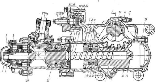
Figure: 4 Steering gear with integrated hydraulic booster:
1- front cover; 2- hydraulic booster control valve; 3, 28-lock rings; 4 - floating bushing; 5, 7-o-rings; 6. 8-spacer rings; 9-set screw; 10 - bipod shaft: 11 - bypass valve; 12-protective cap: 13-back cap; 14-steering gear housing; 15- piston-rack; 16-drain magnetic plug; 17-screw: 18-ball nut; 19-groove; 20-ball; 21 - angular gearbox; 22-thrust roller bearing: 23-spring washer; 24, 26-nuts; 25-adjustment screw; 27-side cover; 29-adjusting washer; 30-thrust washer