GOST R 51709-2001. Motor vehicles. Safety requirements for technical condition and verification methods
STATE STANDARD OF THE RUSSIAN FEDERATION
Motor vehicles
SAFETY REQUIREMENTS FOR TECHNICAL CONDITION AND INSPECTION METHODS
GOST R 51709-2001
Date of introduction 2002.01.01
1 area of use.
This standard applies to cars, buses, trucks, trailers and semi-trailers (hereinafter referred to as motor vehicles) used on highways.
The standard states:
- methods of checking the technical condition of the vehicle in operation.
safety requirements for technical condition vehicles(ATC);
maximum permissible values of the technical condition parameters of vehicles affecting safety road traffic and the state of the environment;
The standard does not apply to vehicles whose maximum speed set by the manufacturer does not exceed 25 km / h, and to off-road vehicles.
Requirements 4.1.1-4.1.7, 4.1.13, 4.1.19, 4.1.21 do not apply to heavy trucks.
The standard should be applied when checking the technical condition of operated vehicles according to safety criteria.
The requirements of the standard are mandatory and are aimed at ensuring road safety, life and health of people, the safety of their property and environmental protection.
The technical condition of the automatic telephone exchange may be subject to additional requirements established by the relevant regulatory documents.
Registered vehicles, in the design of which (including in the design component parts and items of additional equipment) were changes affecting ensuring road safety are checked in accordance with the procedures approved in the prescribed manner.
- GOST 17.2.2.03-87 Nature Protection. Atmosphere, Norms and methods for measuring the content of carbon monoxide and hydrocarbons in the exhaust gases of cars with gasoline engines. Safety requirements.
- GOST R 17.2.02.06-99 Nature protection. Atmosphere. Standards and methods for measuring the content of carbon monoxide and hydrocarbons in the exhaust gases of gas-cylinder vehicles.
- GOST 5727-88 Safety glass for land transport... General technical conditions.
- GOST 8769-75 External lighting devices for cars, buses, trolley buses, tractors, trailers and semi-trailers. Number, location, color, viewing angles.
- GOST 9921-81 Manual tire pressure gauges. General technical conditions.
- GOST 21393-75 Cars with diesel engines. Smoke in the exhaust gases. Norms and methods of measurements. Safety requirements.
- GOST 27902-88 Safety glass for cars, tractors and agricultural machines. Determination of optical properties.
- GOST R 50574-93 Cars, buses and motorcycles of special and operational services. Color schemes, identification marks, inscriptions, special light and sound signals... General requirements.
- GOST R 50577-93 State registration signs of vehicles. Types and basic sizes. Technical requirements.
- GOST R 51253-99 Motor vehicles. Color-graphic schemes for the placement of reflective markings. Technical requirements.
3. Definitions.
The following terms are used in this standard with appropriate definitions:
3.1 road train:
3.2 anti-lock braking system:
3.3 :
3.4 brake system lag time:
3.5 deceleration rise time:
3.6 auxiliary braking system:
3.7 rear protective device:
3.8 spare braking system:
3.9 good condition of the PBX:
3.10 changing the design of the vehicle:
3.12 class of rear-view mirrors:
The class of the mirror is indicated in the marking on the certified rear-view mirrors in Roman numerals.
3.13 wheel brake mechanisms: Devices designed to create artificial resistance to the movement of the vehicle due to friction between rotating and stationary parts of the wheel.
3.14 end of braking: The moment in time at which the artificial resistance to the movement of the vehicle has disappeared or it has stopped. Denoted by a dot TO See Appendix B.
3.15 ATC contour marking:
3.16 traffic corridor:
3.17 place of attachment of seat belts:
3.18 start of braking:
3.19 initial deceleration rate -
3.20 neutral position of the steering wheel (steering wheels):
3.21 brake system control:
3.22 sensory examination:
3.23 reference axis: Line of intersection of planes passing through the center of the lens light fixture parallel to the longitudinal center plane of the vehicle and the support surface.
3.24 full braking: Braking, as a result of which the vehicle stops.
3.25 longitudinal central plane of the vehicle:
3.26 permissible maximum mass:
3.27 ATS and its parts operability: A condition in which the values of the parameters characterizing the ability of the vehicle to carry out transport work meet the requirements of regulatory documents.
3.28 service brake system: A braking system designed to reduce vehicle speed.
3.29 reflective marking material:
3.30 equipped state of automatic telephone exchange: The state of the vehicle without cargo (passengers) with filled containers of power, cooling and lubrication systems, with a set of tools and accessories (including a spare wheel) provided by the vehicle manufacturer in accordance with the operational documentation.
3.31 components and items of ATC equipment:
3.32 parking brake system:
3.33 total steering play:
3.34 technical condition of automatic telephone exchange: The aggregate of the properties subject to change during operation and the ATS parameters established by regulatory documents, which determines the possibility of its intended use.
3.35 braking: The process of creating and changing artificial resistance to the movement of the vehicle.
3.36 braking force: Reaction of the support surface to the vehicle wheels causing braking. To assess the technical condition of the braking systems, the maximum values of the braking forces are used.
3.37 brake system: A set of parts of the vehicle intended for its braking when acting on the control of the brake system.
3.38 brake control:
3.39 brake drive: The set of parts of the braking control, designed for the controlled transmission of energy from its source to braking mechanisms for the purpose of braking.
3.40 braking distance:
3.41 specific braking force:
3.42 steady-state deceleration:
3.43 vehicle stability during braking: The ability of the vehicle to move when braking within the traffic corridor.
3.44 headlights types R, HR:
3.45 headlights of types C, HC: Low beam headlights.
3.46 headlights types CR, HCR:
3.47 type B headlights: Fog lights.
3.48 "cold" braking mechanism:
3.49 emergency braking:
3.50 braking efficiency:
4. Requirements for the technical condition of the automatic telephone exchange.
4.1 Requirements for braking control
Note - The application of indicators of braking efficiency and stability of the vehicle during braking, as well as methods for their verification, is given in 5.1.
4.1.2 In road conditions, when braking with the service brake system with an initial braking speed of 40 km / h, the vehicle should not leave the standard traffic corridor with a width of 3 m with any of its parts.
| Table 1- Standards for the braking efficiency of the vehicle with the working brake system during tests on the stands. | |||||||
| ATC | ATC category | Effort on the control R P, H, no more | Specific braking force γ Т, not less | ||||
| Ml | 490 | 0,59 | |||||
| М2, МЗ | 686 | 0,51 | |||||
| Trucks | N1, N2, N3 | 686 | 0,51 | ||||
| Table2- Standards for the braking efficiency of the vehicle with the working brake system when checking in road conditions. | |||||||
| ATC | Effort on the control R P, H,no more | Braking distance of ATC S T, no more | |||||
| Passenger and utility vehicles | Ml | 490 | 14,7 | ||||
| М2, МЗ | 686 | 18,3 | |||||
| Ml | 490 | 14,7 | |||||
| Trucks | N1, N2, N3 | 686 | 18,3 | ||||
| N1, N2, N3 | 686 | 19,5 | |||||
| Table 3- Standards for the braking efficiency of the vehicle with the working brake system when checking in road conditions. | |||||||
| ATC | ATC category (tractor unit as part of a road train) | Effort on the control R P, H, no more | Steady-state deceleration j mouth m / s 2, not less | Brake response time T T, s, no more | |||
| Passenger and utility vehicles | Ml | 490 | 5,8 | 0,6 | |||
| М2, МЗ | 686 | 5,0 | 0,8 (1,0) | ||||
| Cars with trailers | Ml | 490 | 5.8 | 0,6 | |||
| Trucks | N1, N2, N3 | 686 | 5,0 | 0,8 (1,0) | |||
| Trucks with a trailer (semi-trailer) | N1, N2, N3 | 686 | 5,0 | 0,9 (1,3) | |||
| Note - The values in brackets are for vehicles manufactured before 01.01.81 | |||||||
4.1.3 When checking on stands, the relative difference in the braking forces of the axle wheels (as a percentage of the maximum value) is allowed for vehicles of categories
Ml, M2, МЗ and front axles of cars and trailers of categories Nl, N2, N3.02.03.04 not more than 20%, and for semitrailers and subsequent axles of cars and trailers of categories Nl, N2, N3, О2, О3, О4 - 25%.
4.1.4 When checking the working brake system of trailers and semi-trailers (except for dismantling trailers and semi-trailers with more than three axles) at the stands, the specific braking force must be at least 0.5 for trailers with two or more axles and at least 0.45 - for trailers with one (central) axle and semi-trailers.
4.1.5 The parking braking system for vehicles of the permissible maximum mass must provide a specific braking force of at least 0.16 or a stationary state of the vehicle on a supporting surface with a slope of at least 16%. Parking brake system for vehicles in running order
must provide a design specific braking force equal to 0.6 of the ratio of the unladen weight on the axles, which is affected by the parking brake system, to the unladen weight, or the vehicle's stationary state on the surface with a slope of at least 23% for vehicles of categories M1-MZ and not less than 31% for categories N1-N3.
The gain applied to the control of the parking brake system to activate it should be no more than 392 N for vehicles of category Ml and 588 N for vehicles of other categories.
4.1.6 The auxiliary braking system, with the exception of the engine retarder, when checking in road conditions in the speed range of 25-35 km / h must ensure a steady deceleration of at least 0.5 m / s 2 - for vehicles of the permissible maximum mass and 0.8 m / s 2 - for vehicles in running order, taking into account the driver's weight. The engine retarder must be operable. 4.1.7 The spare braking system, equipped with a control unit independent of other braking systems, must ensure compliance with the standards for the braking performance of the vehicle on the stand in accordance with Table 4, or in road conditions in accordance with Table 5 or 6. The initial braking speed at road tests - 40 km / h.
| Table 4 - Standards for the braking efficiency of the vehicle by the spare braking system during tests at the stands. | |||
| ATC | ATC category | Effort on the control RNS, H, no more | Specific braking force γ T, not less |
| Passenger and utility vehicles | Ml | 490 (392*) | 0,295 |
| М2, МЗ | 686 (589*) | 0,255 | |
| Trucks | N1.N2.N3 | 686 (589*) | 0,220 |
| * For PBX with manual control spare braking system. | |||
| Table 5 - Standards for the braking efficiency of the vehicle by the spare braking system when checking in road conditions. | |||
| ATC | ATC category (tractor unit as part of a road train) | Effort on the control RNS, H, no more | Braking distance of ATC ST, no more |
| Passenger and utility vehicles | Ml | 490 (392*) | 25,3 |
| М2, МЗ | 686 (589*) | 30,6 | |
| Cars with trailers | Ml | 490 (392*) | 25,3 |
| Trucks | N1, N2, N3 | 686 (589*) | 33,8 |
| Trucks with a trailer (semi-trailer) | N1, N2, N3 | 686 (589*) | 35,0 |
| * For vehicles with manual control of the spare brake system. | |||
| Table 6 - Standards for the braking efficiency of the vehicle by the spare braking system when checking in road conditions. | ||||
| ATC | ATC category (tractor unit as part of a road train) | Effort on the control R P, H... no more | Steady-state deceleration j mouth m / s 2 not less | Brake response time τ T, s, no more |
| Passenger and utility vehicles | Ml | 490 (392*) | 2,9 | 0,6 |
| М2, МЗ | 686 (589*) | 2,5 | 0,8(1,0**) | |
| Cars with trailers | Ml | 490 (392*) | 2,9 | 0,6 |
| Trucks | N1, N2, N3 | 686 (589*) | 2,2 | 0,8(1,0**) |
| Trucks with a trailer (semi-trailer) | N1, N2, N3 | 686 (589*) | 2,2 | 0,9(1,3**) |
| * For vehicles with manual control of the spare brake system. ** For vehicles manufactured before 01/01/81 | ||||
4.1.8 It is allowed to drop the air pressure in the pneumatic or pneumohydraulic brake drive when the engine is not running by no more than 0.05 MPa from the value of the lower limit of regulation by the pressure regulator during:
30 min - with the free position of the brake system control;
15 minutes - after full actuation of the brake system control.
Leaks compressed air from wheel brake chambers are not allowed.
4.1.9 For vehicles with an engine, the pressure at the control terminals of the pneumatic brake actuator receivers with the engine running is allowed from 0.65 to 0.85 MPa, and for trailers (semitrailers) - not less than 0.48 MPa when connected to the tractor via a single-wire drive and not less than 0.63 MPa - when connected via a two-wire drive.
4.1.10 The presence of visible places of chafing, corrosion, mechanical damage, kinks or leaks in pipelines or connections in the brake drive, leakage brake fluid, parts in the brake drive with cracks and permanent deformation are not allowed.
4.1.11 The alarm system and control of brake systems, pressure gauges of the pneumatic and pneumohydraulic brake drive, the device for fixing the control of the parking brake system must be operational.
4.1.12 Flexible brake hoses transmitting the pressure of compressed air or brake fluid to the wheel brakes must be connected to each other without additional transition elements (for vehicles manufactured after 01/01/81). The location and length of flexible brake hoses must ensure the tightness of the joints, taking into account the maximum deformations of the elastic suspension elements and the angles of rotation of the vehicle wheels. Swelling of hoses under pressure, cracks and visible chafing points on them are not allowed.
4.1.13 The location and length of the connecting hoses of the pneumatic brake drive of road trains must exclude their damage during mutual movements of the tractor and trailer (semi-trailer).
4.1.14 The action of the service and spare braking systems should be adjustable:
a decrease or increase in the braking force must be ensured by acting on the control of the brake system in the entire range of control of the braking force;
the braking force must change in the same direction as the impact on the control;
the braking force must be adjusted smoothly and without difficulty.
4.1.15 Pressure at the test terminal of the brake force regulator as part of the pneumatic brake actuator in the positions of the permissible maximum mass and the loaded state of the vehicle or the tension force of the free end of the regulator spring, equipped with a linkage with the rear axle, as part of brake hydraulic drive must correspond to the values specified in the manufacturer's plate installed on the vehicle or in the operational documentation.
4.1.16 Vehicles equipped with anti-lock braking systems (ABS), when braking in running order (taking into account the driver's weight) with an initial speed of at least 40 km / h, must move within the traffic corridor without visible traces of skidding and skidding, and their wheels must not must leave traces of skid on the road surface until the ABS is turned off when the speed is reached, corresponding to the ABS shutdown threshold (no more than 15 km / h). The functioning of the ABS warning devices must correspond to its good condition.
4.1.17 The free play of the inertial brake control device for trailers of categories 01 and 02 must comply with the requirements established by the vehicle manufacturer in the operating documentation.
4.1.18 When the inertia brake drive is disconnected for trailers of category 01, the push-in force of the trailer hitch must be at least 200 N, and for trailers of category 02 - at least 350 N.
4.2 Steering requirements
4.2.1 The change in the effort when turning the steering wheel should be smooth over the entire range of its steering angle.
4.2.2 Spontaneous rotation of the steering wheel with the power steering from the neutral position when the vehicle is stationary and the engine is running is not allowed.
4.2.3 The total backlash in the steering must not exceed the limit values specified by the vehicle manufacturer in the operational documentation, or, if such values are not specified by the manufacturer, the following limit values:
- cars and trucks and buses created on the basis of their aggregates ..... 10 °
- buses .......................... 20 °
- trucks ........ 25 °
4.2.4 The maximum turn of the steering wheel shall be limited only by devices provided by the design PBX.
4.2.5 The mobility of the steering column in planes passing through its axis, the steering wheel in the axial direction, the steering gear housing, steering drive parts relative to each other or the supporting surface is not allowed. Threaded connections must be tightened and secured. Backlash in the joints of the pivot pins and the steering rod joints is not allowed. The device for fixing the position of the steering column with an adjustable position of the steering wheel must be functional.
4.2.6 The use of parts with traces of permanent deformation, cracks and other defects in the steering mechanism and steering drive is not allowed.
4.2.7 The tension of the power steering pump drive belt and the level of the working fluid in its reservoir must comply with the requirements established by the vehicle manufacturer in the operating documentation. Leakage of working fluid in the hydraulic system of the amplifier is not allowed.
4.3 Requirements for external lighting devices and reflective markings
4.3.1 The number and color of external lighting devices installed on the vehicle must comply with GOST 8769. Changing the locations of external light devices provided by the manufacturer of the vehicle is not allowed.
4.3.2 It is allowed to install a spotlight or searchlight-searchlight, if provided by the manufacturer. It is allowed to install additional braking signals and replace external lighting devices with those used on vehicles of other brands and models.
4.3.3 Indicators for switching on light devices located in the cab (passenger compartment) must be operable.
4.3.4 Headlamps of types C (HC) and CR (HCR) shall be adjusted so that the plane containing the left (from the vehicle) part of the cut-off line of the passing beam is located as specified in Figure 1 and Table 7 distance values L from the optical center of the headlight to the screen, height H installation of the headlamp in the center of the lens above the plane of the working platform and the angle a of inclination of the light beam to the horizontal plane, or distance R on the screen from the projection of the center of the headlamp to the light border of the light beam and the distances L and H.4.3.5 The luminous intensity of each type C (HC) and CR (HCR) headlamp in dipped beam mode, measured in a vertical plane through the reference axis, shall not exceed 750 cd in the 34 "direction upward part of the cut-off line and not less than 1600 cd in the 52 "direction downward from the position of the left side of the cut-off line.
4.3.6 Type R (HR) headlamps should be adjusted so that the angle of inclination of the brightest (central) part of the light beam in the vertical plane is in the range 0 ... 34 "downward from the reference axis. In this case, the vertical plane of symmetry of the brightest part of the light the beam must pass through the reference axis.
4.3.7. The luminous intensity of type CR (HCR) headlamps in the "high-beam" mode shall be measured in the direction 34 "upward from the position of the left-hand side of the" dipped-beam "cut-off in a vertical plane through the reference axis.
4.3.8. The luminous intensity of Type R (HR) headlamps shall be measured at the center of the brightest part of the light beam.
4.3.9 The luminous intensity of all headlamps of types R (HR) and CR (HCR), located on the same side of the vehicle, in the "high beam" mode must be at least 10,000 cd, and the total luminous intensity of all headlamps of the specified typical shall be more than 225,000 cd.
4.3.10 Fog lamps (type B) shall be adjusted so that the plane containing the upper cut-off of the beam is located as indicated in table 8.
In this case, the upper cut-off border of the fog lamp beam should be parallel to the plane of the working platform on which the vehicle is installed.
4.3.11 The luminous intensity of fog lamps, measured in a vertical plane passing through the reference axis, shall be no more than 625 cd in a direction 3 ° upward from the upper cut-off position and not less than 1000 cd in a direction 3 ° downward from the upper cut-off position. 4.3.12. Fog lights must be switched on when the side lights are on, regardless of whether the main and (or) dipped beam headlights are switched on. 4.3.13 The luminous intensity of each of the signal lights (lanterns) in the direction of the reference axis should be within the limits specified in Table 9. 4.3.14 The luminous intensity of paired lamps of the same functional purpose, symmetrically located on different sides of the vehicle (front or rear), should not differ more than doubled.
4.3.15 Marker, outline lights, as well as the road train identification mark must operate in a continuous mode.
4.3.16 Braking signals (main and additional) must be switched on when acting on the controls of the brake systems and work in a constant mode.
4.3.17 Lantern reverse should turn on when engaging reverse gear and work continuously.
4.3.18 Direction indicators and side indicator repeaters must be functional. The flashing repetition rate must be within (90 + 30) flashes per minute or (1.5 + 0.5) Hz.
4.3.19 Alarm must ensure the synchronous activation of all direction indicators and side repeaters in flashing mode.
4.3.20 The lamp for illumination of the rear state registration plate must be switched on simultaneously with the side lights and work in a constant mode.
4.3.21 Rear Fog lights should be switched on only when the headlamps of the main beam or dipped beam are on, or fog lights and work continuously.
4.3.22 The vehicle must have a reflective marking in accordance with GOST R 51253. Damage and delamination of the reflective marking is not allowed.
4.4 Requirements for wipers and washers
4.4.1 ATS must be equipped with wipers and washers windscreen.
4.4.2 Frequency of movement of brushes on wet glass in mode maximum speed wipers must be at least 35 double strokes per minute.
4.4.3 Washers should provide liquid supply to glass cleaning areas.
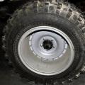
4.5 Requirements for tires and wheels
4.5.1 The tread height of the tires must be at least:
- for passenger cars-1.6 mm;
- for trucks - 1.0 mm;
- for buses - 2.0 mm;
- for trailers and semi-trailers - the same as for the tractors with which they work. The tire is not suitable for use when:
- the presence of a section of the treadmill of the dimensions specified in 5.5.1.1, the height of the tread pattern along the entire length of which is less than the specified standard;
- the appearance of one wear indicator (a protrusion along the bottom of the groove of the treadmill, the height of which corresponds to the minimum permissible height of the tire tread pattern) with uniform wear, or two indicators in each of the two sections with uneven wear of the treadmill.
4.5.2 Twin wheels shall be installed so that the valve holes in the rims are aligned to allow the air pressure and tire inflation to be measured. Replacement of spools with plugs, plugs and other devices is not allowed.
4.5.3 Local damage to tires (punctures, swelling, through and blind cuts) that expose the cord, as well as local peeling of the tread are not allowed.
4.5.4 ATS must be equipped with tires in accordance with the manufacturer's requirements in accordance with the manufacturer's operational documentation or the Operating Rules car tires.
4.5.5 On passenger cars and buses of class I *, it is allowed to use tires retreaded according to class I **, and on their rear axles, in addition, retreated according to classes II and D **.
On the middle and rear axles of buses of classes II and III *, it is allowed to use tires retreaded according to class I **. Fitting retreaded tires on the front axles of these buses is not permitted.
On all axles of trucks, trailers and semi-trailers, it is allowed to use tires retreaded according to classes I, II, III **, and on their rear axles, in addition, also according to class D **.
On the rear axle of cars and buses of classes I, II, III *, middle and rear axles of trucks, on any axles of trailers and semi-trailers, it is allowed to use tires with repaired local damages and a tread pattern with an in-depth cutting method.
4.5.6 The absence of at least one bolt or nut for fastening the discs and wheel rims, as well as loosening of their tightening, is not allowed.
4.5.7 Cracks on the disks and rims of the wheels are not allowed.
4.5.8 Visible violations of the shape and size of the mounting holes in the wheel rims are not allowed.
* Determination of bus classes - according to Appendix A
** Determination of tire retreading classes according to the Rules for the operation of automobile tires.
4.6 Requirements for the engine and its systems
4.6.1 The maximum permissible content of carbon monoxide and hydrocarbons in the exhaust gases of vehicles with gasoline engines is in accordance with GOST 17.2.2.03.
4.6.2 The maximum permissible smoke level of exhaust gases from vehicles with diesel engines is in accordance with GOST 21393.
4.6.3 The maximum permissible content of carbon monoxide and hydrocarbons in the exhaust gases of gas-cylinder vehicles is in accordance with GOST 17.2.02.06.
4.6.4 Fuel leaks in the fuel system gasoline engines and diesels are not allowed. Fuel tank shut-off devices and fuel shut-off devices must be functional. The fuel tank caps must be fixed in the closed position; damage to the sealing elements of the caps is not allowed.
4.6.5 The gas supply system of gas-cylinder vehicles must be hermetically sealed. It is not allowed to use cylinders with expired period of their periodic survey on gas-cylinder vehicles.
4.6.6 There should be no leaks in the joints and elements of the exhaust system, and for vehicles equipped with exhaust gas converters, no leakage into the atmosphere bypassing the converter is allowed.
4.6.7 Disconnection of pipes in the crankcase ventilation system is not allowed.
4.7 Requirements for other structural elements
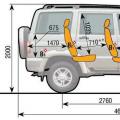
4.7.1 The vehicle must be equipped with rear-view mirrors in accordance with Table 10, as well as glasses, a sound signal and sun visors.
| Table 10 - Requirements for equipping motor vehicles with rear-view mirrors. | |||||||||
| ATC category | Mirror application | Number and location of mirrors on PBX | Mirror characteristic | Class * mirrors | |||||
| 1 | 2 | 3 | 4 | 5 | |||||
| M1, N1 | Mandatory - only if there is a review and through it | One inside the PBX | Internal | 1 | |||||
| Necessarily | One left | Outdoor, main | 3 (or 2) | ||||||
| Mandatory - in case of insufficient visibility through the interior mirror, in other cases - allowed | One on the right | ||||||||
| М2, МЗ | Necessarily | One to the right, one to the left | Outdoor main | 2 | |||||
| Allowed | One on the right | Outdoor wide angle | 4 | ||||||
| Outdoor side view | 5** | ||||||||
| N2 (UP TO 7.5 t) | Necessarily | One to the right, one to the left | Outdoor main | 2 (or 3 on one bracket with 4) | |||||
| Allowed | One inside the PBX | Internal | 1 | ||||||
| One on the right | Outdoor wide angle | 4 | |||||||
| Outdoor side view | 5** | ||||||||
| N2 (over 7.5 t) N3 | Necessarily | One to the right, one to the left | Outdoor main | 2 (or З on one bracket with 4 - only for N2) | |||||
| Allowed | One on the right | Outdoor wide angle | 4 | ||||||
| Outdoor side view | 5** | ||||||||
| One inside the PBX | Internal | 1 | |||||||
| * For the class of rear-view mirrors, see 3.12. ** The mirror must be positioned at least 2 m above the level of the supporting surface. | |||||||||
4.7.2 The presence of cracks on the windshield of the vehicle in the area of cleaning half of the glass by the wiper located on the driver's side is not allowed.
4.7.3 It is not allowed to have additional objects or coatings that limit visibility from the driver's seat (with the exception of rear-view mirrors, parts of windshield wipers, external and applied or built-in radio antennas, heating elements for defrosting and drying the windshield).
In the upper part of the windshield, it is allowed to mount a strip of transparent colored film with a width of not more than 140 mm, and on vehicles of categories MZ, N2, N3 - with a width not exceeding the minimum distance between the upper edge of the windshield and the upper boundary of the zone of its cleaning with a wiper. The light transmission of glasses, including those covered with transparent colored films, must comply with GOST 5727.
Notes:
- If there are blinds and curtains on the rear windows of passenger cars, outside mirrors are required on both sides.
- On the side and rear windows of class 1P buses, it is allowed to use a curtain.
4.7.4 Locks of the body or cab doors, locks of the sides of the cargo platform, locks of the necks of the tanks, adjustment mechanisms and fixing devices for the driver's and passengers' seats, a sound signal, a heating and blowing device for the windshield, an anti-theft device provided by the vehicle manufacturer, an emergency switch for doors and a demand signal bus stops, bus emergency exits and devices for activating them, interior lighting devices of the bus interior, door control drive and signaling of their operation must be operable.
ATS side hinged door locks must be operable and fixed in two locking positions: intermediate and final.
4.7.5 Emergency exits in buses must be marked and have signs according to the rules for their use. It is not allowed to equip the bus interior with additional structural elements restricting free access to emergency exits.
4.7.6 Means for measuring speed (speedometers) and distance traveled must be functional. Tachographs must be functional, metrologically verified in accordance with the established procedure and sealed.
4.7.7 Loosening of bolted connections and destruction of suspension parts and cardan transmission of the vehicle are not allowed.
The lever of the floor (body) level regulator of the vehicle with air suspension in the loaded state must be in the horizontal position. The pressure at the test output of the floor level regulator for vehicles with air suspension, manufactured after 01/01/97, must correspond to that indicated in the manufacturer's plate.
4.7.8 On vehicles of categories N2, N3 and 02-04, dismantling of the rear protective device (RSP) installed by the manufacturer is not allowed. The RUP in length should be no more than the length of the rear axle and no shorter than it by more than 100 mm on each side.
4.7.9 Deformations of the front and rear bumpers of cars, buses and trucks, in which the radius of curvature of the outwardly protruding parts of the bumper (except for parts made of non-metallic elastic materials) is less than 5 mm, is not allowed.
4.7.10 Visible destruction, short circuits and traces of breakdown of the insulation of electrical wires are not allowed.
4.7.11 The lock of the fifth wheel coupling of semitrailer tractors must close automatically after the coupling. Manual and automatic locking of the fifth wheel coupling must prevent spontaneous uncoupling of the tractor and the semi-trailer. Cracks and local destruction of coupling parts are not allowed.
Trailers must be equipped with safety chains (ropes), which must be in good working order. The length of the safety chains (cables) must prevent contact of the drawbar eyelet with the road surface and at the same time ensure the trailer control in case of breakage (breakdown) of the towing hitch. Safety chains (cables) must not be attached to parts of the towing hitch or to its fastening parts.
Trailers (except for single-axle and uncoupled trailers) must be equipped with a device that supports the drawbar hitching eye in a position that facilitates hitching and uncoupling with a towing vehicle.
Longitudinal backlash is not allowed in backlash-free towing hitch devices with a traction fork for a tractor coupled to a trailer.
Traction couplings of passenger cars must ensure a backlash-free coupling of the lock device with a ball. Spontaneous uncoupling is not allowed.
4.7.12 Front towing devices of vehicles (except for trailers and semi-trailers) equipped with these devices must be operable.
4.7.13 The diameter of the coupling pivot of the coupling devices of semi-trailers with a permissible maximum mass of up to 40 t must be in the range from the nominal equal to 50.9 mm to the maximum permissible one of 48.3 mm, and the largest inner diameter of the working surfaces of the coupling grips - from 50 , 8 mm, up to 55 mm.
The diameter in the longitudinal plane of the throat of the pulling hook of the "hook-and-loop" towing system of trucks-tractors must be in the range from the minimum, which is 48.0 mm, to the maximum permissible, equal to 53.0 mm, and the smallest cross-sectional diameter of the bar of the coupling loop - from 43.9 mm to 36 mm.
The diameter of the pivot of backlash-free towing couplings with a drawbar should be within the range from the nominal 38.5 mm to the maximum allowable 36.4 mm.
The diameter of the ball of the towing device of passenger cars must be in the range from the nominal, equal to 50.0 mm, to the maximum allowable, equal to 49.6 mm.
4.7.14 ATS must be equipped with seat belts in accordance with the requirements of operational documents.
The use of seat belts with the following defects is not allowed:
tear on the strap, visible to the naked eye;
the lock does not fix the "tongue" of the strap or does not throw it out after pressing the button of the locking device;
the webbing does not extend or retract into the retractor (coil);
when the strap is pulled sharply, it does not stop (blocking) its pulling out of the retractor (coil) equipped with a double blocking mechanism for the strap.
4.7.15 ATS must be equipped with a first-aid kit, an emergency stop sign (or a flashing red light), and vehicles of categories M3, N2, N3, in addition, also wheel chocks(at least two). Cars and trucks must be equipped with at least one fire extinguisher, and buses and trucks intended for the transport of people - two, one of which must be located in the driver's cab, and the second in the passenger compartment (body). The use of fire extinguishers without seals and (or) with expired shelf life is not allowed. The first aid kit must be equipped with suitable medications.
4.7.16 Bus handrails, spare wheel, batteries, seats, and fire extinguishers and first aid kit on vehicles equipped with devices for their fastening, must be securely fixed in the places provided for by the design of the vehicle.
4.7.17 On vehicles equipped with mechanisms for longitudinal adjustment of the position of the cushion and the angle of inclination of the seat back or a mechanism for moving the seat (for getting in and out of passengers), these mechanisms must be operational. After the termination of regulation or use, these mechanisms should be automatically blocked.
4.7.18 The height of the head restraint from the seat cushion in the free (uncompressed) state, on vehicles manufactured after 01.01.99 and equipped with non-height-adjustable head restraints, must be at least 800 mm, the height of the adjustable head restraint in the middle position - (800 + 5) mm ... For vehicles manufactured before 01.01.99, the specified value may be reduced to (750 + 5) mm.
4.7.19 The vehicle must be equipped with the wheel-mounted dirt protection devices provided for by the design. The width of these devices must be at least the width of the tires used.
4.7.20 The vertical static load on the towing device of the vehicle from the hitching eye of a single-axle trailer (dismantling trailer) in the loaded state should not exceed 490 N. support leg must be equipped with a lifting-lowering mechanism that ensures the installation of the towing eye in the position of the hitch (uncoupling) of the trailer with the tractor.
4.7.21 Spare wheel holder, winch and spare wheel lifting and lowering mechanism must be functional. The winch ratchet device must clearly fix the drum with the lashing rope.
4.7.22 Semi-trailers must be equipped with a supporting device that must be functional. Retainers transport position supports, designed to prevent their spontaneous lowering when the vehicle is moving, must be operational. The mechanisms for raising and lowering the supports must be functional. The ratchet device of the winches for lifting and lowering the supports must clearly fix the drum with the lashing rope, preventing it from sagging.
4.7.23 Dropping of oils and working fluids from the engine, gearbox, final drives, rear axle, clutch, battery, cooling and air conditioning systems and additional hydraulic devices installed on the vehicle are not allowed.
4.7.24 Equipment of automatic telephone exchanges with special light and (or) sound signals, application of special color-graphic coloring in accordance with GOST R 50574 without the appropriate permission is not allowed.
4.7.25 Color schemes for painting vehicles of operational and special services, special light and sound signals must comply with GOST R 50574.
4.7.26 Placement of special light signals not on the roof of the vehicle body (cabin) is not allowed.
4.8 Requirements for vehicle marking
4.8.1 ATS manufactured after 01.01.2000 must be marked, the content and location of which must comply with the requirements of regulatory documents.
4.8.2 Public registration plates on the PBX must be installed and fixed on designated locations according to GOST R 50577.
4.8.3 For vehicles equipped with a gas supply system, on the outer surface of the gas cylinders, their passport data, including the dates of the current and subsequent survey, must be marked.
5. Methods of verification.
5.1 Methods for checking brake control
5.1.1 Characteristics of brake control test methods.
5.1.1.1 The efficiency of braking and stability of the vehicle during braking is checked at stands or in road conditions.
5.1.1.2. The working and spare braking systems are checked for the braking efficiency and stability of the vehicle during braking, and the parking and auxiliary braking systems - for the braking efficiency. The use of indicators and methods for checking the effectiveness of braking and stability of the vehicle during braking by various braking systems is summarized in Appendix B.
5.1.1.3 Measuring instruments used for verification shall be operable and metrologically verified. The measurement error should not exceed when determining:
braking distance +5,0 %
initial braking speed +1.0 km / h
braking force +3.0%
efforts at the governing body +7.0%
brake system response time +0.03 s
brake system lag time +0.03 s
deceleration rise time + 0.03 s
steady-state deceleration + 4.0%
air pressure in pneumatic or pneumohydraulic brake actuator + 5.0%
pushing force of the coupling device of trailers equipped with an inertial brake + 5.0%
longitudinal slope of the platform for braking +1.0%
vehicle weight +3.0%
NOTE The requirement for the stopping distance measurement error does not apply to the calculated determination. this indicator according to Appendix G.
5.1.1.4 It is allowed to check the indicators of braking efficiency and stability of the vehicle during braking by methods and methods equivalent to those established by this standard, if they are regulated by regulatory documents.
5.1.2 Conditions for checking the technical condition of the brake control
5.1.2.1. The vehicle is tested with "cold" brakes.
5.1.2.2 The tires of the vehicle tested at the vehicle stand must be clean, dry, and the pressure in them must comply with the standard established by the vehicle manufacturer in the operating documentation. The pressure is checked in completely cooled tires using pressure gauges corresponding to GOST 9921.
5.1.2.3 Checks at stands and on the road (except for checking the auxiliary brake system) are carried out with the engine running and disconnected from the transmission, as well as with the drives disconnected, additional driving axles and unlocked transmission differentials (if the specified units are available in the vehicle design).
5.1.2.4 Indicators according to 4.1.1, 1.4.1.3-4.1.5 are checked on a roller stand for checking brake systems, if there are categories on the front seat of the vehicle
Ml-N1 driver and passenger. The force of impact on the control of the brake system is increased to the value provided for in 4.1.1 or 4.1.5, or 4.1.7, during the actuation time in accordance with the manual (instructions) for the operation of the stand.
5.1.2.5 Wear of the stand rollers until the corrugated surface is completely erased or the abrasive coating of the rollers is destroyed.
5.1.2.6. Road checks shall be carried out on a straight, level, horizontal, dry, clean road with cement or asphalt concrete pavement. Braking by the service brake system is carried out in the emergency full braking mode by a single action on the control. The time for full activation of the brake system control shall not exceed 0.2 s.
5.1.2.7 Correction of the vehicle trajectory during braking when checking the service braking system in road conditions is not allowed (unless it is required to ensure the safety of checks). If such an adjustment has been made, then the results of the check are not taken into account.
5.1.2.8 The total mass of the technical means of diagnostics used for checks in road conditions shall not exceed 25 kg.
5.1.2.9 Vehicles equipped with ABS are checked in the road conditions specified in 5.1.2.6.
5.1.2.10 When carrying out inspections of the technical condition on the stands and on the road, the instructions for work safety and the manuals (instructions) for the operation of the roller stand must be observed.
5.1.3 Checking the service brake system
5.1.3.1 For checking at the stands, vehicles are sequentially installed with the wheels of each of the axles on the rollers of the stand. Disconnect the engine, additional drive axles from the transmission and unlock the transmission differentials, start the engine and set the minimum stable speed crankshaft... Measurements are carried out in accordance with the manual (instructions) for the operation of the roller stand. For roller stands that do not measure the mass of the vehicle wheels, use weighing devices or reference data on the vehicle mass. Measurements and registration of indicators on the stand are performed for each vehicle axle and the indicators of the specific braking force and the relative difference in the braking forces of the axle wheels are calculated according to 4.1.1, 4.1.3, 4.1.4.
5.1.3.2 For road trains, when checking on stands, the values of the specific braking force must be determined separately for the tractor and the trailer (semitrailer) equipped with the brake control. The obtained values are compared with the standards for vehicles with an engine according to 4.1.1, and for trailers and semi-trailers - according to 4.1.4.
5.1.3.3 When checking the vehicle braking efficiency in road conditions without measuring the braking distance, it is allowed to directly measure the steady-state deceleration and response time of the braking system or calculate the stopping distance indicator according to the method specified in Appendix D, based on the results of measuring the steady-state deceleration, the brake system lag time and a deceleration ramp-up time at a given initial deceleration speed.
5.1.3.4 When checking on stands, the relative difference in braking forces is calculated according to Appendix D and the resulting value is compared with the maximum permissible according to 4.1.3. Measurements and calculations are repeated for the wheels of each vehicle axle.
5.1.3.5 The stability of the vehicle when braking in road conditions is checked by performing braking within the standard traffic corridor. The axis, right and left boundaries of the traffic corridor are preliminarily designated by parallel markings on the road surface. Before braking, the vehicle must move in a straight line with the set initial speed along the axis of the corridor. The exit of the vehicle by any of its parts outside the standard traffic corridor is established visually by the position of the vehicle projection onto the supporting surface or by the device for testing brake systems in road conditions when the measured value of the displacement of the vehicle in the transverse direction exceeds half the difference between the width of the standard traffic corridor and the maximum width of the vehicle.
5.1.3.6 When checking in road conditions the braking efficiency of the working brake system and the stability of the vehicle during braking, deviations of the initial braking speed from the value specified in 4.1.1, 4.1.2, no more than +4 km / h are allowed. In this case, the braking distance standards must be recalculated according to the methodology described in Appendix D.
5.1.3.7 Based on the results of performing checks in road conditions or at stands, the indicators specified in 5.1.3.3, 5.1.3.5 or 5.1.3.1, 5.1.3.2, 5.1.3.4, respectively, are calculated using the methodology described in Appendix D. The vehicle is considered to have passed the test of braking efficiency and stability when braking with the service braking system if the calculated values of these indicators correspond to the standards given in 4.1.1-4.1.4. For vehicles that are not equipped with ABS, instead of compliance with the specific braking force standards 4.1.1, it is allowed to block all the wheels of the vehicle on the stand rollers.
5.1.4 Checking the parking and emergency braking system
5.1.4.1 Checking the parking brake system in road conditions is carried out by placing the vehicle on the supporting surface with a slope equal to that specified in 4.1.5. brake system, and the subsequent disconnection of the service brake system. The verification determines the possibility of providing stationary ATS under the influence of the parking brake system for at least 1 min.
5.1.4.2. Testing at the stand is carried out by alternately driving the stand rollers into rotation and braking the wheels of the vehicle axle, which is affected by the parking brake system. A force according to 4.1.5 is applied to the control body of the parking brake system, controlling it with an error not exceeding that specified in 5.1.1.3. Based on the results of the check, similar to that described in 5.1.3.1, calculate the specific braking force according to the method described in Appendix D, taking into account the notes to Table A.1 in Appendix A, and compare the obtained value with the standard value calculated according to 4.1.5. The vehicle is considered to have passed the braking efficiency test with the parking brake system if the specific braking force is not less than the calculated standard or if the wheels of the tested axle are blocked on the stand rollers according to 4.1.5.
5.1.4.3 Requirements 4.1.7 are checked at the stands by the methods established for checking the service brake system in 5.1.2.1-5.1.2.4, 5.1.2.9, 5.1.3.1,5.1.3.2,5.1.3.7.
5.1.5 Checking the auxiliary brake system
5.1.5.1. The auxiliary braking system is checked in road conditions by activating it and measuring the vehicle deceleration when braking in the speed range specified in 4.1.6. In this case, the transmission of the vehicle must be engaged in a gear that excludes exceeding the maximum permissible engine speed.
5.1.5.2 An indicator of the braking performance of the auxiliary braking system on the road is the steady-state deceleration value. The vehicle is considered to have passed the braking efficiency test by the auxiliary braking system if the steady-state deceleration corresponds to the normative one in 4.1.6. 5.1.6 Checking units and parts of brake systems 5.1.6.1 Requirements 4.1.8, 4.1.9 and 4.1.15 are checked using pressure gauges or electronic meters connected to test leads or connecting heads of the brake drive of a stationary tractor and trailer. When using pressure drop meters with smaller measurement errors, it is allowed to adjust the standards for the measurement period and the maximum allowable air pressure drop in the brake drive according to the method described in Appendix E. When checking the requirement 4.1.15 to the value of the spring tension of the brake force regulator, a dynamometer is used. Leaks in wheel brake chambers are detected using an electronic compressed air leak detector or organoleptically.
5.1.6.2 Requirements 4.1.10, 4.1.12-4.1.13 are checked visually on a stationary vehicle.
5.1.6.3 Requirements 4.1.11 are checked on a stationary vehicle with the engine running by visual observation of the working functioning of the tested units.
5.1.6.4 Requirements 4.1.14 are checked on the stands or on the road during checks of the braking efficiency and stability of the vehicle when braking with the service brake system according to 5.1.3 without performing additional braking by observing the nature of the change in braking forces or deceleration of the vehicle when acting on the body brake system control.
5.1.6.5 Requirements 4.1.16 are checked in road conditions by means of preliminary acceleration of the vehicle, speed control, execution emergency braking and observation of traces of braking of wheels, as well as visual control functioning of the ABS signaling devices in all modes of its operation.
6.1.6.6 The requirements of 4.1.17 are checked using a ruler.
5.1.6.7 The requirements of 4.1.18 are checked by disconnecting the brake inertial-mechanical drive rod from the control device and applying force to the coupling head using a compression dynamometer with an error not exceeding that specified in 5.1.1.3.
5.2 Steering test methods
5.2.1 Requirements 4.2.1, 2.4.2.4 are checked on a stationary vehicle with the engine running by alternately turning the steering wheel to maximum angle in each direction.
5.2.2 Requirement 4.2.2 is checked by observing the position of the steering wheel on a stationary vehicle with power steering after setting the steering wheel to a position approximately corresponding to straight-line movement and starting the engine.
5.2.3 Requirement 4.2.3 is checked on a stationary vehicle using devices for determining the total backlash in the steering, fixing the steering wheel rotation angle and the beginning of the steering wheel rotation.
5.2.3.1 The steered wheels must be preliminarily brought to a position approximately corresponding to straight-line movement, and the engine of the vehicle equipped with the power-assisted steering must be running.
5.2.3.2 Wheel turn to the position corresponding to the beginning of the rotation of the controlled wheels of the vehicle in one direction, and then in the other direction to the position corresponding to the beginning of the rotation of the controlled wheels in the opposite direction. In this case, the angle between the indicated extreme positions of the steering wheel is measured, which is the total backlash in the steering.
5.2.3.3 The maximum measurement error of the total backlash is not more than 1 °. The vehicle is considered to have passed the test if the total backlash does not exceed the standards in 4.2.3.
5.2.4 The requirements of 4.2.5 are checked organoleptically on a stationary vehicle with the engine off by applying loads to the steering units and tapping the threaded connections.
5.2.4.1 Axial displacement and oscillation of the steering wheel, oscillation of the steering column is carried out by applying alternating forces to the steering wheel in the direction of the steering shaft axis and in the plane of the steering wheel perpendicular to the column, as well as alternating moments of forces in two mutually perpendicular planes passing through the axis of the steering column ...
5.2.4.2 Mutual movements of the steering drive parts, the fastening of the steering gear housing and the pivot pins levers are checked by turning the steering wheel relative to the neutral position by 40 ° - 60 ° in each direction and applying an alternating force directly to the steering drive parts. To visually assess the condition of the hinge joints, use stands for checking the steering drive.
5.2.4.3 The operability of the device for fixing the position of the steering column is checked by activating it and then swinging the steering column with its fixed position by applying alternating forces to the steering wheel in the plane of the steering wheel perpendicular to the column in mutually perpendicular planes passing through the axis of the steering column.
5.2.5 Requirements of 4.2.6 are checked visually on a stationary vehicle.
5.2.6 Requirements 4.2.7 are checked by measuring the tension of the power steering pump drive belt on a stationary vehicle using special devices for simultaneous control of effort and displacement or using a ruler and a dynamometer with a maximum error of not more than 7%.
5.3 Methods for checking external lighting devices and reflective markings
5.3.1 Requirements 4.3.1, 4.3.3, 4.3.12, 4.3.15 - 4.3.17, 4.3.19 - 4.3.21 are checked visually, including when turning on and off lighting devices.
5.3.2 The requirements of 4.3.2,4.3.22 are checked visually.
5.3.3 Requirements 4.3.4-4.3.11,4.3.13,4.3.14 are checked with the vehicle engine off at a special post equipped with a working platform, a flat screen with a matte finish, a light meter with a photodetector (protected from extraneous light) and a device, orienting the mutual arrangement of the PBX and the screen. Requirements 4.3.4,4.3.6,4.3.10 are checked on vehicles in running order (except for vehicles of category Ml), and on vehicles of category ML - with a load (70 + 20) kg on the driver's seat (person or cargo).
5.3.3.1 The dimensions of the working platform should, when the vehicle is placed on it, ensure a distance of at least 5 m between the lens of the vehicle light device and the screen along the reference axis. The unevenness of the working platform is allowed no more than 3 mm per 1 m.
5.3.3.2 The angle between the plane of the screen and the work platform shall be (90 + 3) °.
5.3.3.3 The orienting device must ensure that the vehicle is installed in such a way that the reference axis of the lighting device is parallel to the plane of the working platform and is in the plane perpendicular to the planes of the screen and the working platform with an error of not more than + 0.5 °.
5.3.3.4 The screen layout should provide verification of the requirements of 4.3.4-4.3.8,4.3.10,4.3.11. The permissible error when measuring indicators according to 4.3.4 and 4.3.10 should not be more than: for angular values .... + 15 ", for linear values at a distance of 10 m to the screen ..., + 44 mm, at a distance of 5 m to the screen .... + 22 mm.
5.3.3.5 When checking the requirements of 4.3.13, 4.3.14, the photodetector is placed at a distance (3 + 0.1) m from the lens of the light device along its reference axis.
5.3.4 To check the requirements of 4.3.4-4.3.8,4.3.10,4.3.11 it is allowed to use a measuring device with an orienting device instead of a screen.
5.3.4.1 The diameter of the lens inlet should not be less than the size of the headlamp.
5.3.4.2 The optical axis of the measuring device should be directed parallel to the working platform with an error of not more than + 0.25 °.
5.3.4.3 A movable screen with markings shall be installed in the focal plane of the lens to ensure verification of the requirements of 4.3.4-4.3.8,4.3.10,4.3.11.
5.3.4.4 The orienting device should ensure the installation of the optical axis of the device parallel to the longitudinal plane of symmetry of the vehicle (or perpendicular to the axis of the rear wheels) with an error of not more than + 0.5 °.
5.3.5 Measurements of luminous intensity 4.3.5, 4.3.9, 4.3.11, 4.3.13 are carried out using a photodetector adjusted to the average curve of the spectral sensitivity of the eye. The sensitivity of the photodetector must correspond to the intervals of allowable luminous intensity values according to 4.3.5, 4.3.9, 4.3.11, 4.3.13. The permissible error when measuring indicators according to 4.3.5, 4.3.9, 4.3.11,4.3.13, 4.3.18 should not exceed 7%.
The diameter of the photodetector should be no more than 30 mm - when working with a screen according to 5.3.3 and no more than 6 mm - when working with a measuring device according to 5.3.4.
5.3.6 Requirements 4.3.18 to the repetition rate of flashes of direction indicators are checked by at least 10 flashes using a measuring device or a universal time meter with a countdown from 1 to 60 s and a division value of not more than 1 s.
5.4 Methods for checking wipers and washers
The performance of the wipers and washers is checked visually during their working operation at a minimum stable crankshaft speed at Idling ATC engine. Headlights must be on when checking electrically operated wipers high beam... The requirements of 4.4.2 are checked using a universal time meter with a countdown from 1 to 60 s (hours, stopwatch, etc.) and a graduation of no more than 1 s.
5.5 Methods for checking tires and wheels
5.5.1 The requirements of 4.5.1 are checked by measuring the residual height of the tire tread pattern using special templates or a ruler.
5.5.1.1 The height of the pattern with uniform wear of the tire tread is measured in the area bounded by a rectangle, the width of which is not more than half the width of the tread track, and the length is equal to 1/6 of the tire circumference (corresponds to the length of the arc, the chord of which is equal to the tire radius), located in the middle tread track, and in case of uneven wear - in several areas with different wear, the total area of which has the same value.
5.5.1.2. The height of the pattern is measured at the places where the tread is most worn out, but not at the areas where the wear indicators, half-bridges and steps are located at the base of the tread pattern.
The limit wear of tires with wear indicators is recorded with uniform wear of the tread pattern by the appearance of one indicator, and with uneven wear - by the appearance of two indicators in each of the two sections of the wheel.
The height of the tread pattern of tires having a solid rib in the center of the treadmill is measured at the edges of this rib.
The height of the tread pattern of off-road tires is measured between the lugs in the center or in the places least distant from the center of the treadmill, but not along the ledges at the base of the lugs and not along the half-bridges.
5.5.2 Requirements 4.5.3-4.5.8 are checked visually and by tapping bolted joints and fastening parts of disks and wheel rims.
5.6 Methods for checking the engine and its systems
5.6.2 The requirements of 4.6.2 are checked in accordance with GOST 21393.
5.6.3 The requirements of 4.6.3 are checked in accordance with GOST 17.2.02.06.
5.6.4 The requirements of 4.6.4-4.6.6 are checked organoleptically and by activating the shut-off devices of the fuel tanks and the fuel shut-off devices while the engine is running. The technical condition of the fuel tank lids is checked by double opening and closing, the safety of the sealing elements of the lids is checked visually. Tightness gas system the power supply is checked using a special indicator device - a leak detector.
5.6.5 The requirements of 4.6.7 are checked visually.
5.7 Methods for checking other structural elements
5.7.1 Requirements 4.7.1-4.7.3,4.7.5,4.7.10,4.7.12,4.7.15,4.7.26 are checked visually. The light transmission of glasses according to 4.7.3 is checked according to GOST 27902.
5.7.2 Requirements 4.7.4,4.7.11,4.7.14,4.7.17,4.7.21,4.7.22,4.7.24,4.7.25 are checked by inspection, actuation and observation of the functioning and technical condition of the vehicle parts ...
5.7.3 Requirements 4.7.6 are checked visually by changing the speedometer readings when the vehicle is moving in road conditions or on a roller stand to check the speedometers, or to check the traction and power qualities. The performance of the tachographs is checked organoleptically.
5.7.4 The requirements of 4.7.7 are checked visually and by tapping the bolted connections, and, if necessary, using a torque wrench. The pressure at the test terminal of the floor level regulator is measured with a manometer or an electronic meter, the maximum measurement error for which does not exceed 5.0%.
5.7.5 Requirements 4.7.8, 4.7.18,4.7.19 are checked visually and using a ruler, and requirement 4.7.18 is allowed to be checked using a special template.
5.7.6 Requirements 4.7.9, 4.7.13 are checked visually using special templates for checking the inner and outer diameters of wearing parts or by measuring the indicated diameters with a vernier caliper after disengaging the tractor and the trailer (semi-trailer).
5.7.7 The requirements of 4.7.16 are checked by applying non-standardized forces to parts of the vehicle.
5.7.8 The requirements of 4.7.20 are checked by measuring the vertical load on the trailer hitching eye with a dynamometer in the drawbar position corresponding to the hitch position.
5.7.9 The requirements of 4.7.23 are checked visually after 3 minutes. after stopping the vehicle, with the engine running.
5.8 Methods of checking the vehicle marking.
Requirements 4.8.1-4.8.3 are checked visually.
5.6.1 The requirements of 4.6.1 are checked in accordance with GOST 17.2.2.03. 4.1.1 The service braking system of the vehicle must ensure compliance with the braking performance standards on the stands in accordance with Table 1 or in road conditions in Table 2 or 3. The initial braking speed when checking in road conditions is 40 km / h. Vehicle weight during checks should not exceed the maximum allowed. A measure of braking that characterizes the ability of the braking system to create the necessary artificial resistance to the movement of the vehicle. Braking in order to reduce the speed of the vehicle as quickly as possible. A brake mechanism, the temperature of which, measured at the friction surface of the brake drum or brake disc, less than 100 ° C. Low and high beam headlamps High beam headlamps Average deceleration value during braking τ mouth from the end of the deceleration ramp-up time period to the end of deceleration. Denoted j mouth in Appendix B. The ratio of the sum of the braking forces on the wheels of the vehicle to the product of the mass of the vehicle and the acceleration of gravity (for a tractor and a trailer or semi-trailer is calculated separately). The distance traveled by the vehicle from the beginning to the end of braking. The totality of all vehicle braking systems. The angle of rotation of the steering wheel from the position corresponding to the beginning of the rotation of the controlled wheels of the vehicle in one direction to the position corresponding to the beginning of their rotation in the opposite direction. A braking system designed to keep the vehicle stationary. Units, assemblies and parts installed and (or) used in the design of the vehicle, which are subject to requirements regulated by regulatory documents. A surface or device from which, in the presence of radiation, a relatively large portion of the light rays of the original radiation are reflected in their direction. The maximum mass of the equipped vehicle with cargo (passengers), set by the manufacturer as the maximum permissible according to the operational documentation. A plane perpendicular to the plane of the bearing surface and passing through the middle of the vehicle track. Inspection performed with the senses of a qualified technician without the use of measuring instruments. A set of devices designed to give a signal to start braking and to control the energy coming from the energy source or accumulator to the braking mechanisms. The position corresponding to the rectilinear movement of the vehicle in the absence of disturbing influences. vehicle speed at the beginning of braking. The point in time at which the braking system receives a signal to brake. Denoted by a dot H See Appendix B. Part of the body structure (cab) or any other part of the vehicle (for example, the seat frame) to which the seat belt is attached. The part of the support surface, the right and left boundaries of which are marked so that during the movement, the horizontal projection of the vehicle onto the plane of the support surface does not intersect them with a single point. A series of strips of reflective material designed to be applied to the vehicle to indicate its dimensions (outline) from the side (side markings) and from the rear (rear markings) Type of mirrors characterized by one of the following combinations of characteristics and functions: class 1 - interior rear-view mirrors flat or spherical; class 2 - the main external rear-view mirrors are spherical; class 3 - the main external rear-view mirrors are flat or spherical (a smaller radius of curvature is allowed than for class 2 mirrors); class 4 - wide-angle external spherical mirrors; class 5 - external spherical side-view mirrors Subdivision of the vehicle in accordance with the classification adopted in the Geneva Agreement (see Appendix A). Exclusion of components and items of equipment provided for or installation not provided for by the design of the vehicle that affect its safety characteristics. Condition corresponding all the requirements of regulatory documents for the design and technical condition of vehicles. Brake system designed to reduce the speed of vehicles in the event of failure of the service brake system. A brake system designed to reduce the energy load on the brakes of the ATS service brake system. The time interval of a monotonous increase in deceleration until the moment at which the deceleration takes on a steady value. Denoted τ n in Appendix B. Time interval from the start of braking until the appearance of deceleration (braking force). Denoted τ c in Appendix B. The time interval from the start of braking to the moment at which the vehicle deceleration takes on a steady-state value during checks in road conditions (indicated by t cp in Appendix B), or until the moment at which the braking force during tests at stands or takes a maximum value , or the ATS wheel is blocked on the stand rollers. When checking on stands, the response time is measured for each of the wheels of the vehicle. ATS brake system with automatic control during braking of the degree of slippage of the vehicle wheels in the direction of their rotation. A vehicle consisting of a tractor unit and a semi-trailer or trailer (s) connected by a towing device (s)
Portal "Dangerous Cargo" is an association of participants in the market of hazardous substances and products.
6. Requirements for the technical condition and equipment of vehicles
6.1. General Provisions
6.1.1. The technical condition, equipment and staffing of vehicles of all types, brands, purposes, trailers and semitrailers in operation must comply with the requirements of the current regulatory enactments.
6.1.2. The following requirements are imposed on the cab (cabin) of the automatic telephone exchange:
side windows should be smoothly moved by window lifting mechanisms;
no dips, torn places, protruding springs and sharp corners are allowed on the seat and back of the seat;
noise, vibration, microclimate and concentration harmful substances in the cabin of a truck, inside the cabin and the cabin of a bus and the body of a passenger car must comply with the values specified in the current state standards, sanitary standards and rules, hygiene standards;
the heating devices of the cabin and interior must be operational in cold weather; it is prohibited to use exhaust gases as a coolant for heating the cab and interior; they can only be used to heat the coolant;
the floor of the cab, passenger compartment and vehicle body must be covered with a mat that has no holes or other damage.
6.1.3. The controls of the vehicle must be with serviceable seals to prevent the penetration of exhaust gases into the cab or the passenger compartment of the car (bus).
6.1.4. The wheel discs must be securely attached to the hubs. The locking rings of the wheel disks must be in good condition and correctly installed in their places. Cracks and bending of wheel rims are prohibited.
6.1.5. The technical condition of the ATS electrical equipment should ensure that the engine is started with a starter, uninterrupted and timely ignition of the mixture in the engine cylinders, the trouble-free operation of lighting, signaling and electrical devices. control devices, and also to exclude the possibility of sparking in wires and clamps. All wires of electrical equipment must have reliable, undamaged insulation. The battery must be clean and secure. Do not leak electrolyte from the battery monoblock.
6.1.6. Each vehicle must be provided with special stops (at least two pieces) for placing under the wheels, a wide pad under the heel of the jack, as well as a first aid kit, an emergency stop sign or a flashing red light and a fire extinguisher.
6.1.7. Buses and trucks, adapted for the transport of people and specially equipped for these purposes, must be additionally equipped with a second fire extinguisher, with one fire extinguisher located in the driver's cab, the second in the passenger compartment of the bus or the body of a car in accordance with the requirements of current regulatory enactments.
6.1.8. When heading to a long-distance flight (lasting more than 1 day), trucks and buses must be additionally supplied with metal tragus, a shovel, a towing device, a safety fork for the wheel lock ring, and in winter time- additionally with snow chains.
6.1.9. The crankshaft ratchet must have slots that are not worn out and the starter handle must have a straight pin of appropriate length and strength. The starter grip must be smooth and free from burrs.
6.1.10. The exhaust pipes and muffler must be free of cracks and breakdowns, and their connections must not allow exhaust gases to pass through. The end of the exhaust pipe must be free of dents and damage.
Harvesting vehicles must have exhaust pipes equipped with spark arresters.
6.1.11. ATS with lifting cabins must have serviceable latches on the cab stops.
6.1.12. Cab doors, hoods must be with serviceable opening stops and latches for open and closed positions.
6.2. Additional requirements for trucks, trailers, semi-trailers
6.2.1. Cargo body onboard vehicle, trailer and semi-trailer must not have broken beams and boards; the technical condition of the sides should exclude the possibility of cargo falling out when the vehicle is moving.
6.2.2. The sides of the body must open freely (recline), have serviceable hinges and locks.
6.2.3. For one-time transportation of passengers, the body of a cargo onboard vehicle must be equipped with a ladder or brackets for boarding and disembarking, with seats fixed at a height of 0.3-0.5 m from the floor and at least 0.3 m from the upper edge of the side. When transporting children, the sides must have a height of at least 0.8 m from the floor level. Seats along the back and side boards must have strong backs; side locks must be securely fastened; the number of people carried must not exceed the number of seats equipped.
6.2.4. A truck used for the constant transport of people must be equipped with:
an awning or other device that protects transported people from atmospheric influences;
flat floor without through holes and slots;
sound and light signaling associated with the cabin;
stationary or removable ladder for boarding and disembarking people from the rear side;
the exhaust pipe of the muffler, extended beyond the dimensions of the body by 30-50 mm.
A lorry and semi-trailer with a body of the "van" type used for the transport of people and goods with mandatory escort by people, in addition, must have:
serviceable, outward opening doors located at the back or on the right side of the body;
a working device for fixing the doors in the open position;
serviceable locks, excluding spontaneous door opening while driving;
steps located directly under the doors for people to enter and exit;
a device for heating in the cold season;
a second fire extinguisher located in the body.
6.2.5. Trailers, semi-trailers and trucks intended for the transportation of long loads must be equipped with serviceable folding racks and shields (the latter are installed between the cab and the load), have turntables equipped with devices for securing these circles when the vehicle is moving without load.
6.2.6. The turntables of trailers must have serviceable stoppers to prevent the trailer from turning when moving backward.
6.2.7. Trailers (except for dismantling) must have serviceable devices that support the drawbar hitching loop in a position convenient for hitching to and uncoupling with a tractor.
6.2.8. Single-axle trailers (except for dismantling), as well as trailers without brakes, must have safety (emergency) chains or cables that prevent the trailer from breaking off in the event of a breakdown of the coupling. Chains (cables) must not be attached to the vehicle's drawbar or its attachment parts.
Single-axle trailers (except for dismantling) must also have serviceable support legs that ensure the stability of the trailer in the uncoupled state.
6.2.9. All trailers and semi-trailers, with the exception of single-axle ones, must have a working parking brake that ensures the trailer is held after it is disconnected from the tractor, as well as at least two wheel chocks (shoes).
6.2.10. Semi-trailers must be equipped with:
serviceable devices serving as front supports when they are disconnected from the towing vehicle;
serviceable saddle devices.
6.2.11. Dump trucks and dump trailers must have serviceable devices of the required strength, excluding the possibility of spontaneous lowering of the raised body.
On the sides of a dump truck, the inscription "Do not work without a stop under a raised body" should be applied with a bright indelible paint, and a KamAZ dump truck - "Do not work under a raised body without installing a stopper".
6.2.12. The opening side of a dump truck or dump trailer must fit snugly to the body and exclude the loss of cargo, spontaneous opening of the side is prohibited.
6.2.13. The exhaust pipe of the muffler of a car carrying fire and explosive goods must not pass under the body and must be led out to the right under the front of the car (in the direction) with the outlet slope down.
6.2.14. Trucks with a closed body designed for the transport of flammable and toxic substances in small containers and barrels must have natural ventilation of the body.
6.2.15. Capacity (container) for transportation dangerous goods must have a clearly visible warning inscription and signs in accordance with the requirements of the current state standards.
6.2.16. ATS, designed for the transportation of dangerous goods, is additionally equipped with equipment and fire extinguishing means in accordance with applicable regulations.
6.2.17. A truck used for technical assistance must additionally have:
van type body;
a workbench with a bench vise and a set of tools, fixtures and fittings for car repairs on the line;
special boxes with cells for storing tools, spare parts, accessories;
additional sources of lighting (floodlights, portable low-voltage lamps) for repairs at night;
rigid towing devices and cables, entrenching tools and snow chains;
metal tragus and wheel stops;
additional tanks for the delivery of fuel, oil and equipment for their safe refueling (hoses, pumps, funnels, etc.);
scuttlebutt;
devices for pulling out and lifting of crashed vehicles, as well as removable protective grilles on the front glass.
6.3. Additional requirements for gas-fueled vehicles
6.3.1. Technical condition of cars running on gas fuel, must comply with the requirements of technical specifications and instructions of manufacturers of gas-cylinder vehicles or gas-cylinder equipment.
6.3.2. The equipment, pipelines, main and flow valves must be sealed, excluding the penetration of gas into the cabin, body, and also into the atmosphere.
Tightness gas equipment on the vehicle must be checked in accordance with the requirements of the current regulations.
CNG cylinders must meet the requirements of applicable government standards and other regulations.
6.3.3. Gas cylinders installed on a car must be painted red, have passport data printed on them in accordance with the current state standard and other regulatory enactments and an inscription with white paint "Propane" or "Methane".
6.3.4. It is not allowed to operate vehicles on gas cylinders of which:
no passport data;
the period of examination has expired;
there is external damage (corrosion, cracks, potholes, shells, etc.);
adapters and valves are faulty;
coloring and inscriptions do not meet the requirements.
6.3.5. Gas cylinders must be securely attached to the vehicle.
6.3.6. Gas pipes high pressure should be colored red.
6.3.7. It is not allowed to operate gas-fueled vehicles with faulty gas equipment. After troubleshooting the elements of the gas supply system or replacing the gas cylinders, the tightness of the gas supply system must be checked.
6.4. Requirements for the conversion of motor vehicles to operate on gas fuel
6.4.1. Under the operating conditions of automatic telephone exchanges, the installation of gas equipment on them for operation on CNG or GOS is carried out in accordance with the requirements of the current state standards and other regulations.
6.4.2. When preparing a vehicle for the installation of LPG equipment, you must:
wash the PBX ( engine compartment, cab, frame, etc.);
drain gasoline from fuel tank and pipelines of the power supply system, if the technology of installing gas equipment requires the removal of the fuel tank from the car.
6.4.3. When performing electrical work, the following requirements must be observed:
the fixed wires should not turn relative to the terminals of the devices;
wires going to the engine compartment to the sensor low pressure gas, solenoid petrol valve, solenoid gas valve, solenoid start valve and other elements of electrical equipment of gas-cylinder equipment, should not touch the heating parts of the vehicle;
it is forbidden to touch the metal parts of the automatic telephone exchange with the current-carrying terminals of the devices and wire ends;
wires should not be located on sharp edges and edges of vehicle parts;
insulating tubes must be tightly seated on the wire ends;
sharp bends of the wires, as well as twisting and pulling them after connecting to electrical equipment, are not allowed.
6.4.4. The installation of cylinders on the vehicle must be done using lifting devices after making sure that there is no gas in the cylinders.
6.4.5. CNG cylinders installed on vehicles must be of the same steel grade and have the same inspection period.
When installing such cylinders on a vehicle, it is necessary to maintain the distances from the neck to the structural elements corresponding to the technical documentation. Rubber gaskets must be laid in the places where the cylinders are attached.
The cylinders must be secured in such a way that the possibility of their rotation and movement is excluded.
6.4.6. Before installing high pressure gas pipelines, blow them out with compressed air and inspect them (no cracks or damage).
6.4.7. The switch "mass" must be installed in the vehicle cab in a place convenient for the driver.
6.4.8. When installing adapters and valves on cylinders, the following requirements must be observed:
cylinders must meet the requirements of the Gosgortekhnadzor of Russia, approved in the prescribed manner;
to ensure tightness, tapered threads must be lubricated (with lead litharge, liquid glass or lead red lead);
the force when tightening the tapered threads of adapters and valves must correspond to 450-500 N (45-50 kgf), for which torque wrenches are used;
when installing adapters and valves, the cylinder must be installed in a special clamping device that prevents it from turning;
Adapters and valves newly screwed into the cylinder should have no more than 2-3 threads of thread that are not included in the threaded sockets of the neck of the cylinder.
6.4.9. After installing the LPG equipment at the vehicle, the gas supply system must be checked for leaks and pressurized in accordance with the requirements of the current regulatory enactments.
In the future, the vehicle must be operated in accordance with the requirements of the manual for the operation of the gas-cylinder vehicle attached to the set of gas-cylinder equipment installed on the vehicle.
6.5. Additional requirements for specialized vehicles
6.5.1. Specialized vehicles (cars, trailers and semi-trailers with different bodies designed for the carriage of various goods) must meet the relevant technical conditions.
6.5.2. All ladders, walkways and work platforms at the vehicle must be kept in good condition and free of dirt, ice and snow.
6.5.3. Work platforms located at a height of more than 1.3 m must be equipped with serviceable fencing (railings).
6.5.4. Each panel carrier must be equipped with two tragus for support under the semitrailer frame during loading and unloading operations.
6.5.5. To secure loads on panel transporters, winches, safety chains with hooks, as well as cables with angles should be provided.
6.5.6. Tank cars for the transportation of flammable and combustible liquids must have an inscription "Flammable", at least two fire extinguishers, a shovel and a grounding device (a metal chain welded at one end to the body of the tank).
6.5.7. Tank trucks for the transport of flammable and hazardous liquids, as well as bitumen must have serviceable "breathing" valves that ensure the tightness of the tanks within the specified limits.
6.5.8. The drain fittings of the road tankers must exclude the possibility of leakage.
6.5.9. When transporting liquids, tankers must have serviceable devices to control its level.
6.5.10. Tank trucks for the transport of liquid and bulk goods must have grounding devices.
6.5.11. Tank trucks for the transportation of bulk cargo with pneumatic unloading must be equipped with serviceable pressure gauges, clearly visible from the control panel. Control panels must be illuminated.
6.5.12. The loading hatch covers of road tankers must have serviceable quick-acting locks to ensure the tightness of the tanks.
6.5.13. Tank trucks under pressure must comply with the requirements for pressure receptacles.
6.5.14. The inner walls of the bodies of cars or refrigerated semi-trailers must not have scuff marks and sharp edges.
6.5.15. Cars and semi-trailers with a "van" type body must have good lighting inside the body, providing an illumination of at least 5 lux.
6.5.16. Lifting mechanisms, control devices for raising (lowering) the body, sides, etc. on specialized automatic telephone exchanges must be serviceable.
Moving parts (gears, belts, chains, etc.) must be properly guarded.
2. REQUIREMENTS FOR TECHNICAL CONDITION
AND ROLLING STOCK EQUIPMENT
2.1 GENERAL REQUIREMENTS
The study and analysis of road accidents show that they occur mainly due to violations of the rules of the road and the unsatisfactory technical condition of vehicles.
The technical condition and equipment of vehicles in operation must meet the requirements of GOST 25478-82. Of the Rules technical operation rolling stock of road transport, traffic rules. Regulations on labor protection in road transport, instructions of manufacturers, registration documents and other regulatory and technical documentation.
Technically faulty vehicles should not be allowed to operate.
Particular attention must be paid to the technical condition of the brake system, due to a malfunction of which the most severe accidents occur. Before releasing the car on the line, you should inspect the brake system, check the effectiveness of its action and, if any malfunctions are found, immediately eliminate them.
Cars are not allowed for operation if: the design of the brake systems has been changed; brake fluid, units or individual parts are used that are not provided for this car model or do not meet the requirements of the manufacturer; the tightness of the hydraulic brake drive is broken; violation of the tightness of the pneumatic brake drive causes a drop in air pressure when the compressor is not working by 0.05 MPa in 30 minutes with the free position of the brake system controls or in 15 minutes with the controls turned on; the pressure gauge of the pneumatic brake drive does not work; the parking brake lever is not held by the locking device; during road tests, the norms of the braking efficiency of the service brake system are not observed; the parking brake system does not provide a stationary state on a slope of less than 16% - vehicles with full load, 23% - cars and their modifications for the carriage of goods, buses in curb condition, 31% - trucks and road trains in “curb condition. the parking brake system, the engine must be disconnected from the transmission.
Road tests of the working brake system are carried out on a horizontal section of the road with a smooth, dry and clean cement or asphalt concrete pavement with an initial braking speed of 40 km / h.
The braking distance for cars in running order, taking into account the driver's weight, should be no more than, m:
Cars
and their modifications for the carriage of goods ……………………… 14.5
GVW buses
up to 5 tons inclusive ………………………………………… 18.7
The same over 5 tons …………………………………………… 19.9
Trucks with a gross weight of up to 3.5 ............................................. 19.0
The same from 3.5 to 12 tons inclusive ……………… .. ………… .18.8
The same over 12 tons …………………………………… ... ……… 17.7
Road trains with tractor vehicles with a gross weight of up to 3.5 tons inclusive ……………………………………… .. ……… ..22,7
The same from 3.5 to 12 tons inclusive ………………. …… ..22.1
The same over 12 tons …………………………………….… ... 21.9
The test results shall be invalidated if the driver has to correct the trajectory in order to maintain a straight heading during braking.
During bench tests of the working brake system, as well as when checking the effectiveness of the spare (emergency) and auxiliary brake systems, the standards in accordance with GOST 25478-82 are applied.
Steering should provide ease and reliability of front wheels control at any speed and in various road conditions. The technical condition of the steering is judged by the total backlash. For cars of certain types, it must not exceed the following limit values, degrees:
Passenger cars and created
on their basis, cargo modifications and buses ........................... 10
Buses ................................................. ..................................... twenty
Trucks................................................ ................. 25
In steering, tangible mutual movements of parts and assemblies, or their movement relative to the body (chassis, cab, frame) of the car, not provided for by the design, are unacceptable. All screw connections must be tight or secure. The steering system should not use parts with traces of permanent deformation and other defects, as well as parts and working fluids that are not provided for this car model or do not meet the manufacturer's requirements.
It should be remembered that increased gaps in the joints of the steering elements, wear and deformation of parts, loosening of their fastening lead to vibration of the front of the car, loss of stability, and sometimes even control of the car.
The condition of the car's running gear is determined by an external examination of suspension parts, disks, wheels and tires, by checking the axial play of wheel bearings, the angles of the front wheels.
The normal technical condition of the running gear means reliable suspension mounting, correct positioning of the front and rear axles relative to the frame or body. Bends, cracks in the frame beams or suspension parts are unacceptable; destruction of the root leaf or the central bolt of the spring, damage to the springs.
Wheel disks must be securely fixed in the hubs, they must not have cracks, bends, developed holes or annular grooves, as well as faulty locking rings and damaged fastening parts.
One of the main guarantees for the safe movement of a car is tires. Traffic rules prohibit the operation of a vehicle if: a passenger car tire has a residual tread height of less than 1.6 mm, a truck tire - 1.0 mm, a bus - 2.0 mm (for trailers and semi-trailers, the norms are the same as for tractor vehicles ); tires have local damage (cuts, breaks), exposing the cord, as well as delamination of the carcass, peeling of the tread and sidewalls; there are foreign objects between the twin tires; tire by size and permissible load does not match the car model; on one axle there are diagonal and radial tires, as well as tires with different tread patterns. Cannot be mounted on front axles intercity bus tires remanufactured according to the first or second class of repair, and on other axles - according to the second class of repair. Tires, retreaded according to the second class of repair, cannot also be installed on the front axle of a passenger car and buses (except for intercity buses).
When operating the car, it is necessary to ensure that the internal air pressure in the tires is maintained within the established norms. In addition, at each TO-1 and TO-2, the pressure should be measured and, if necessary, inflated tires.
The axial play (tightening) of the wheel bearings is checked with a hoist or jack suspended front wheel... If the bearings are adjusted correctly, then when the wheel is swinging in the axial direction, there should be no noticeable backlash, and after pushing by hand, the wheel should make several revolutions. You should be aware that weak or strong tightening can lead to the destruction of the bearings, and strong, in addition, can cause the hubs to heat up and jam the wheels.
The angles of the front wheels (toe, camber) are checked during TO-2 on special diagnostic stands or using the TsPKTB ruler. Improper alignment of the front wheels leads to accelerated tire wear and poor vehicle handling.
To the car engine from the point of view of safety and fire safety have the following requirements. Cooling and lubrication systems must be free of oil, antifreeze and water leaks. The crankcase ventilation must work properly, excluding the breakthrough of gases into the engine compartment. The ratchet of the crankshaft must be with unfilled slots, and the starting handle must have a straight pin of the appropriate length and strength and a smooth, burr-free handle. The car is not allowed to operate if; the content of harmful substances in the exhaust gases or their smokiness exceeds the established standards; the fuel system is leaking; the exhaust system is faulty; there are no devices to suppress interference with radio reception. It is not allowed to make changes in the design of the engine, as well as to install devices and equipment for operation on another type of fuel without the consent of the manufacturer.
The technical condition of the vehicle's electrical equipment must ensure reliable engine start-up with a starter, uninterrupted and timely ignition of the mixture in the engine cylinders. trouble-free operation of lighting devices, alarms and electrical control devices, as well as exclude the possibility of sparking in wires and clamps. All wires must have reliable insulation. The battery must be securely fastened. The monoblock should not have cracks or damage, electrolyte leakage from the monoblock is not allowed.
Traffic safety is also influenced by the state of external lighting devices, which ensure driving at night and in fog, signaling car maneuvers and accidents. Incorrect headlight adjustment and the simultaneous inclusion of low and high beam can lead to dazzling of drivers of oncoming vehicles. It is necessary to keep lighting devices and reflectors clean, timely cleaning them from dirt, dust and adhered snow, to maintain their performance in the prescribed mode. The headlights should be checked and adjusted periodically.
All cars must be provided with a set of serviceable tools, a first-aid kit, a fire extinguisher, an emergency stop sign (flashing red light). Trucks with a GVW of 3.5 t and buses with a GVW of over 5 t also provide wheel chocks. Buses and specially equipped trucks for transporting people are equipped with two fire extinguishers. One of the fire extinguishers must be in the driver's cab and the other in the passenger compartment of a bus or the body of a truck.
Tank cars for the transportation of flammable and combustible liquids must have at least two fire extinguishers, a felt felt, a shovel, a grounding device (a metal chain welded at one end to the tank body).
A constructive way to increase the comfort of a truck
The body of the bus is designed to accommodate passengers during their mass transportation. It is a complex structure, which consists of about three thousand parts ...
Survey of road conditions and improvement of traffic safety on Sovetskaya street in the city of Volgodonsk
Let's analyze the correspondence of the elements of st. Soviet for compliance with the requirements of GOST R 50797-93. The pavement of the carriageway has slight subsidence, several large potholes, the dimensions of which exceed 15 cm in length ...
Determination of the financial condition of road transport by city bus by route taxis
Km. (5) Where: lcc is the average daily mileage of the bus, km. (6), km. We will enter the calculation results into table No. 1: Table No. 1 No. p / p Name of indicators Value 1. Auto days in operation ADE 4216363 2. Auto hours in operation ACHE 59872354 3 ...
Features of the movement of the fighter
Theorem 1: A linear non-stationary system is fully controllable by state only if the matrix has a rank: 2 Initial data Option No. 2, Mode No. 8. 1) ...
Selection diagnostic equipment during the reconstruction of the municipal unitary enterprise "Volgograd Passenger Motor Transport Enterprise No. 7"
The braking system of cars, consisting of braking mechanisms and their drive, is designed to reduce the speed of movement up to a complete stop with a minimum braking distance ...
Selection of diagnostic equipment during the reconstruction of the municipal unitary enterprise "Volgograd Passenger Motor Transport Enterprise No. 7"
In accordance with the requirements of GOST R 51709-2001, the parameters of the technical condition of the steering must meet the requirements set forth below. The change in effort when turning the steering wheel should be smooth over the entire range of its rotation ...
Road transport certification program
The engine compartment must be designed to prevent accumulation of fuel or lubricant in any place of it, for which, if necessary, drainage holes can be provided ...
The bus is sent for overhaul if necessary overhaul body. During its service life, the bus undergoes no more than one major overhaul ...
Reconstruction project of the production base "Kostanayavtotrans"
Design of a service station for passenger cars on Shosseinaya street in the Sheksna village of the Vologda region
To ensure the competitiveness of the service technical center, it is necessary to take into account a number of requirements: - ensuring the convenience of the place ...
Development of technology and organization of passenger transportation
Average daily mileage of a working bus: Lav.day = Ve * Tn; (21) Lav.day = Ve * Tn = 22.1 * 11, 4 = 251.94 km. Total mileage for all buses for the year Ltot = Lav.day * ADe; (22) Ltot = 251.94 * 6588 = 1659780.7 km. Useful mileage of buses: Lpol = Ltot * in; (23) Lpol = 1659780.7 * 0.95 = 1576791.7 km ...
The technology of repairing the cylinder-piston group of a car with the development of a device for pressing out piston pins
The condition of the exhaust gases can be used to accurately determine the condition of the engine. If black smoke appears from the exhaust pipe, this indicates incomplete fuel combustion ...
Stable and efficient functioning of the transport complex of the Republic of Belarus
To substantiate the volume of traffic for the prospect of design, an analysis of the work was carried out bus fleet over the last 5 years. The analysis results are presented in table. 2 ...
Operation and maintenance of cranes and scrapers
Engines installed on road construction machines internal combustion work in extremely unfavorable conditions - high dustiness of the environment, often severe climatic conditions ...
Posted:2007-07-06GOST R 51709-2001. Safety requirements for technical condition and test methods
STATE STANDARD OF THE RUSSIAN FEDERATION
Motor vehicles
SAFETY REQUIREMENTS FOR TECHNICAL CONDITION AND INSPECTION METHODS
GOST R 51709-2001
Date of introduction 2002.01.01
1 area of use.
This standard applies to cars, buses, trucks, trailers and semi-trailers (hereinafter referred to as motor vehicles) used on highways.
The standard states:
- methods of checking the technical condition of the vehicle in operation.
safety requirements for the technical condition of vehicles (ATS);
the maximum permissible values of the parameters of the technical condition of vehicles that affect road safety and the state of the environment;
The standard does not apply to vehicles whose maximum speed set by the manufacturer does not exceed 25 km / h, and to off-road vehicles.
Requirements 4.1.1-4.1.7, 4.1.13, 4.1.19, 4.1.21 do not apply to heavy trucks.
The standard should be applied when checking the technical condition of operated vehicles according to safety criteria.
The requirements of the standard are mandatory and are aimed at ensuring road safety, life and health of people, the safety of their property and environmental protection.
The technical condition of the automatic telephone exchange may be subject to additional requirements established by the relevant regulatory documents.
Registered vehicles, in the design of which (including in the design of components and items of additional equipment) there have been changes affecting ensuring road safety, are checked in accordance with the procedures approved in the prescribed manner.
- GOST 17.2.2.03-87 Nature Protection. Atmosphere, Norms and methods for measuring the content of carbon monoxide and hydrocarbons in the exhaust gases of cars with gasoline engines. Safety requirements.
- GOST R 17.2.02.06-99 Nature protection. Atmosphere. Standards and methods for measuring the content of carbon monoxide and hydrocarbons in the exhaust gases of gas-cylinder vehicles.
- GOST 5727-88 Safety glass for land transport. General technical conditions.
- GOST 8769-75 External lighting devices for cars, buses, trolley buses, tractors, trailers and semi-trailers. Number, location, color, viewing angles.
- GOST 9921-81 Manual tire pressure gauges. General technical conditions.
- GOST 21393-75 Cars with diesel engines. Smoke in the exhaust gases. Norms and methods of measurements. Safety requirements.
- GOST 27902-88 Safety glass for cars, tractors and agricultural machines. Determination of optical properties.
- GOST R 50574-93 Cars, buses and motorcycles of special and operational services. Color schemes, identification marks, inscriptions, special light and sound signals. General requirements.
- GOST R 50577-93 State registration signs of vehicles. Types and basic sizes. Technical requirements.
- GOST R 51253-99 Motor vehicles. Color-graphic schemes for the placement of reflective markings. Technical requirements.
3. Definitions.
The following terms are used in this standard with appropriate definitions:
3.1 road train: A vehicle consisting of a tractor unit and a semi-trailer or trailer (s) connected by a towing device (s)
3.2 anti-lock braking system: ATS brake system with automatic control during braking of the degree of slippage of the vehicle wheels in the direction of their rotation.
3.3 : The time interval from the start of braking to the moment at which the vehicle deceleration takes on a steady-state value during checks in road conditions (indicated by tav in Appendix B), or until the moment at which the braking force during tests at stands either takes a maximum value, or the vehicle wheel is blocked on the stand rollers. When checking on stands, the response time is measured for each of the wheels of the vehicle.
3.4 brake system lag time: The time interval from the start of braking until the appearance of deceleration (braking force). Denoted τ c in Appendix B.
3.5 deceleration rise time: Time interval of monotonic growth of deceleration until the moment at which the deceleration takes on a steady-state value. Denoted τ See Appendix B.
3.6 auxiliary braking system: A brake system designed to reduce the energy load on the brakes of the ATS service brake system.
3.7 rear protective device: Part of the structure of vehicles of categories N2, N3, O3 and O4, designed to protect cars of categories ML and N1 from falling under them when they are hit from behind.
3.8 spare braking system: A brake system designed to reduce the speed of the vehicle in the event of failure of the service brake system.
3.9 good condition of the PBX: Condition that meets all the requirements of regulatory documents for the design and technical condition of the vehicle.
3.10 changing the design of the vehicle: Exclusion of components and items of equipment provided for or installation not provided for by the design of the vehicle, affecting its safety characteristics.
3.12 class of rear-view mirrors: A type of mirrors characterized by one of the following combinations of characteristics and functions: class 1 - interior rear-view mirrors, flat or spherical; class 2 - the main external rear-view mirrors are spherical; class 3 - the main external rear-view mirrors are flat or spherical (a smaller radius of curvature is allowed than for class 2 mirrors); class 4 - wide-angle external spherical mirrors; class 5 - external spherical side-view mirrors.
The class of the mirror is indicated in the marking on the certified rear-view mirrors in Roman numerals.
3.13 wheel brake mechanisms: Devices designed to create artificial resistance to the movement of the vehicle due to friction between rotating and stationary parts of the wheel.
3.14 end of braking: The moment in time at which the artificial resistance to the movement of the vehicle has disappeared or it has stopped. Denoted by a dot TO See Appendix B.
3.15 ATC contour marking: A series of stripes of reflective material, intended for application to the vehicle to indicate its dimensions (outline) from the side (side markings) and from the back (rear markings).
3.16 traffic corridor: The part of the support surface, the right and left boundaries of which are marked so that during the movement, the horizontal projection of the vehicle onto the plane of the support surface does not intersect them with a single point.
3.17 place of attachment of seat belts: The part of the body structure (cab) or any other part of the vehicle (for example, the seat frame) to which the seat belt is attached.
3.18 start of braking: The point in time at which the braking system receives a signal to brake. Denoted by a dot H See Appendix B.
3.19 initial deceleration rate - vehicle speed at the beginning of braking.
3.20 neutral position of the steering wheel (steering wheels): The position corresponding to the rectilinear movement of the vehicle in the absence of disturbing influences.
3.21 brake system control: A set of devices designed to give a signal to start braking and to control the energy coming from the energy source or accumulator to the braking mechanisms.
3.22 sensory examination: Inspection performed with the senses of a qualified technician without the use of measuring instruments.
3.23 reference axis: The line of intersection of the planes passing through the center of the lens of the light device parallel to the longitudinal center plane of the vehicle and the reference surface.
3.24 full braking: Braking, as a result of which the vehicle stops.
3.25 longitudinal central plane of the vehicle: A plane perpendicular to the plane of the bearing surface and passing through the middle of the vehicle track.
3.26 permissible maximum mass: The maximum mass of the equipped vehicle with cargo (passengers), set by the manufacturer as the maximum permissible according to the operational documentation.
3.27 ATS and its parts operability: A condition in which the values of the parameters characterizing the ability of the vehicle to carry out transport work meet the requirements of regulatory documents.
3.28 service brake system: A braking system designed to reduce vehicle speed.
3.29 reflective marking material: A surface or device from which, in the presence of radiation, a relatively large portion of the light rays of the original radiation are reflected in their direction.
3.30 equipped state of automatic telephone exchange: The state of the vehicle without cargo (passengers) with filled containers of power, cooling and lubrication systems, with a set of tools and accessories (including a spare wheel) provided by the vehicle manufacturer in accordance with the operational documentation.
3.31 components and items of ATC equipment: Units, assemblies and parts installed and (or) used in the design of the vehicle, which are subject to requirements regulated by regulatory documents.
3.32 parking brake system: A braking system designed to keep the vehicle stationary.
3.33 total steering play: The angle of rotation of the steering wheel from the position corresponding to the beginning of the rotation of the controlled wheels of the vehicle in one direction to the position corresponding to the beginning of their rotation in the opposite direction.
3.34 technical condition of automatic telephone exchange: The aggregate of the properties subject to change during operation and the ATS parameters established by regulatory documents, which determines the possibility of its intended use.
3.35 braking: The process of creating and changing artificial resistance to the movement of the vehicle.
3.36 braking force: Reaction of the support surface to the vehicle wheels causing braking. To assess the technical condition of the braking systems, the maximum values of the braking forces are used.
3.37 brake system: A set of parts of the vehicle intended for its braking when acting on the control of the brake system.
3.38 brake control: The totality of all vehicle braking systems.
3.39 brake drive: A set of parts of the braking control, designed for the controlled transfer of energy from its source to the braking mechanisms in order to perform braking.
3.40 braking distance: Distance traveled by the vehicle from start to end of braking.
3.41 specific braking force: The ratio of the sum of the braking forces on the wheels of the vehicle to the product of the mass of the vehicle and the acceleration of gravity (for a tractor unit and a trailer or semitrailer is calculated separately).
3.42 steady-state deceleration: Average deceleration during deceleration τ setpoint of the end of the deceleration rise time period until the end of deceleration. Denoted j in Appendix B.
3.43 vehicle stability during braking: The ability of the vehicle to move when braking within the traffic corridor.
3.44 headlights types R, HR: High beam headlights.
3.45 headlights of types C, HC: Low beam headlights.
3.46 headlights types CR, HCR: Headlights of low and high beam.
3.47 type B headlights: Fog lights.
3.48 "cold" braking mechanism: Brake mechanism, the temperature of which, measured on the friction surface of the brake drum or brake disc, is less than 100 ° C.
3.49 emergency braking: Braking in order to reduce the speed of the vehicle as quickly as possible.
3.50 braking efficiency: A measure of braking that characterizes the ability of the braking system to create the necessary artificial resistance to the movement of the vehicle.
4. Requirements for the technical condition of the automatic telephone exchange.
4.1 Requirements for braking control
4.1.1 The service braking system of the vehicle must ensure compliance with the braking performance standards on the stands in accordance with Table 1 or in road conditions in Table 2 or 3. The initial braking speed when checking in road conditions is 40 km / h. Vehicle weight during checks should not exceed the maximum allowed.
Note - The application of indicators of braking efficiency and stability of the vehicle during braking, as well as methods for their verification, is given in 5.1.
4.1.2 In road conditions, when braking with the service brake system with an initial braking speed of 40 km / h, the vehicle should not leave the standard traffic corridor with a width of 3 m with any of its parts.
Table 1- Standards for the braking efficiency of the vehicle with the working brake system during tests on the stands. |
|||||||
Effort on the control RP , H, no more |
Specific braking force γТ, not less |
||||||
Passenger and cargo-passenger cars |
|||||||
Trucks |
|||||||
|
Table2- Standards for the braking efficiency of the vehicle with the working brake system when checking in road conditions. |
|||||||
Effort on the control RP |
Braking distance of ATC ST, no more |
||||||
Trucks |
|||||||
|
3- Standards for the braking efficiency of the vehicle with the working brake system when checking in road conditions. |
|||||||
Effort on the control RP, H, no more |
Steady-state deceleration |
Brake response time T T, s, no more |
|||||
Passenger and utility vehicles |
|||||||
Cars with trailers |
|||||||
Trucks |
|||||||
Trucks with a trailer (semi-trailer) |
|||||||
Note Values in brackets - for vehicles manufactured before 01.01.81 |
|||||||
4.1.3 When checking on stands, the relative difference in the braking forces of the axle wheels (as a percentage of the maximum value) is allowed for vehicles of categories
Ml, M2, МЗ and front axles of cars and trailers of categories Nl, N2, N3.02.03.04 not more than 20%, and for semitrailers and subsequent axles of cars and trailers of categories Nl, N2, N3, О2, О3, О4 - 25%.
4.1.4 When checking the working brake system of trailers and semi-trailers (except for dismantling trailers and semi-trailers with more than three axles) at the stands, the specific braking force must be at least 0.5 for trailers with two or more axles and at least 0.45 - for trailers with one (central) axle and semi-trailers.
4.1.5 The parking braking system for vehicles of the permissible maximum mass must provide a specific braking force of at least 0.16 or a stationary state of the vehicle on a supporting surface with a slope of at least 16%. Parking brake system for vehicles in running order
must provide a design specific braking force equal to 0.6 of the ratio of the unladen weight on the axles, which is affected by the parking brake system, to the unladen weight, or the vehicle's stationary state on the surface with a slope of at least 23% for vehicles of categories M1-MZ and not less than 31% for categories N1-N3.
The gain applied to the control of the parking brake system to activate it should be no more than 392 N for vehicles of category Ml and 588 N for vehicles of other categories.
4.1.6 The auxiliary braking system, with the exception of the engine retarder, when checking in road conditions in the speed range of 25-35 km / h must ensure a steady deceleration of at least 0.5 m / s2 - for vehicles of the permissible maximum mass and 0.8 m / c2 - for vehicles in running order, taking into account the driver's weight. The engine retarder must be operable. 4.1.7 The spare braking system, equipped with a control unit independent of other braking systems, must ensure compliance with the standards for the braking performance of the vehicle on the stand in accordance with Table 4, or in road conditions in accordance with Table 5 or 6. The initial braking speed at road tests - 40 km / h.
Table 4 - Standards for the braking efficiency of the vehicle by the spare braking system during tests at the stands. |
|||
Effort on the control RNS ,H, no more |
Specific braking force γ T, not less |
||
Passenger and utility vehicles |
|||
Trucks |
|||
* For vehicles with manual control of the spare brake system. |
|||
|
Table 5 - Standards for the braking efficiency of the vehicle by the spare braking system when checking in road conditions. |
|||
Effort on the control RNS ,H, no more |
Braking distance of ATC ST, no more |
||
Passenger and utility vehicles |
|||
Cars with trailers |
|||
Trucks |
|||
Trucks with a trailer (semi-trailer) |
|||
* For vehicles with manual control of the spare brake system. |
|||
Table 6 - Standards for the braking efficiency of the vehicle by the spare braking system when checking in road conditions. |
||||
Effort on the control NS,H... no more |
Steady-state deceleration j mouth m / s2 |
Brake response time τТ, s, no more |
||
Passenger and utility vehicles |
||||
Cars with trailers |
||||
Trucks |
||||
Trucks with a trailer (semi-trailer) |
||||
* For vehicles with manual control of the spare brake system. ** For vehicles manufactured before 01/01/81 |
||||
4.1.8 It is allowed to drop the air pressure in the pneumatic or pneumohydraulic brake drive when the engine is not running by no more than 0.05 MPa from the value of the lower limit of regulation by the pressure regulator during:
30 min - with the free position of the brake system control;
15 minutes - after full actuation of the brake system control.
Leakage of compressed air from wheel brake chambers is not allowed.
4.1.9 For vehicles with an engine, the pressure at the control terminals of the pneumatic brake actuator receivers with the engine running is allowed from 0.65 to 0.85 MPa, and for trailers (semitrailers) - not less than 0.48 MPa when connected to the tractor via a single-wire drive and not less than 0.63 MPa - when connected via a two-wire drive.
4.1.10 The presence of visible places of chafing, corrosion, mechanical damage, kinks or leakage of pipelines or connections in the brake drive, brake fluid leakage, parts in the brake drive with cracks and permanent deformation are not allowed.
4.1.11 The alarm system and control of brake systems, pressure gauges of the pneumatic and pneumohydraulic brake drive, the device for fixing the control of the parking brake system must be operational.
4.1.12 Flexible brake hoses transmitting the pressure of compressed air or brake fluid to the wheel brakes must be connected to each other without additional transition elements (for vehicles manufactured after 01/01/81). The location and length of flexible brake hoses must ensure the tightness of the joints, taking into account the maximum deformations of the elastic suspension elements and the angles of rotation of the vehicle wheels. Swelling of hoses under pressure, cracks and visible chafing points on them are not allowed.
4.1.13 The location and length of the connecting hoses of the pneumatic brake drive of road trains must exclude their damage during mutual movements of the tractor and trailer (semi-trailer).
4.1.14 The action of the service and spare braking systems should be adjustable:
a decrease or increase in the braking force must be ensured by acting on the control of the brake system in the entire range of control of the braking force;
the braking force must change in the same direction as the impact on the control;
the braking force must be adjusted smoothly and without difficulty.
4.1.15 The pressure at the test terminal of the brake force regulator as part of the pneumatic brake actuator in the positions of the permissible maximum mass and the loaded condition of the vehicle or the tension force of the free end of the regulator spring, equipped with a linkage with the rear axle, as part of the hydraulic brake actuator must correspond to the values specified in the ATC manufacturer's plate or operational documentation.
4.1.16 Vehicles equipped with anti-lock braking systems (ABS), when braking in running order (taking into account the driver's weight) with an initial speed of at least 40 km / h, must move within the traffic corridor without visible traces of skidding and skidding, and their wheels must not must leave traces of skid on the road surface until the ABS is turned off when the speed is reached, corresponding to the ABS shutdown threshold (no more than 15 km / h). The functioning of the ABS warning devices must correspond to its good condition.
4.1.17 The free play of the inertial brake control device for trailers of categories 01 and 02 must comply with the requirements established by the vehicle manufacturer in the operating documentation.
4.1.18 When the inertia brake drive is disconnected for trailers of category 01, the push-in force of the trailer hitch must be at least 200 N, and for trailers of category 02 - at least 350 N.
4.2 Steering requirements
4.2.1 The change in the effort when turning the steering wheel should be smooth over the entire range of its steering angle.
4.2.2 Spontaneous rotation of the steering wheel with the power steering from the neutral position when the vehicle is stationary and the engine is running is not allowed.
4.2.3 The total backlash in the steering must not exceed the limit values specified by the vehicle manufacturer in the operational documentation, or, if such values are not specified by the manufacturer, the following limit values:
- cars and trucks and buses created on the basis of their aggregates ... 10 °
- buses ................................................. .................................................. ........................... 20 °
- trucks................................................ ..................... ... ............................ ........ 25 °
4.2.4 The maximum turn of the steering wheel should be limited only by devices provided by the vehicle design.
4.2.5 The mobility of the steering column in planes passing through its axis, the steering wheel in the axial direction, the steering gear housing, steering drive parts relative to each other or the supporting surface is not allowed. Threaded connections must be tightened and secured. Backlash in the joints of the pivot pins and the steering rod joints is not allowed. The device for fixing the position of the steering column with an adjustable position of the steering wheel must be functional.
4.2.6 The use of parts with traces of permanent deformation, cracks and other defects in the steering mechanism and steering drive is not allowed.
4.2.7 The tension of the power steering pump drive belt and the level of the working fluid in its reservoir must comply with the requirements established by the vehicle manufacturer in the operating documentation. Leakage of working fluid in the hydraulic system of the amplifier is not allowed.
4.3 Requirements for external lighting devices and reflective markings
4.3.1 The number and color of external lighting devices installed on the vehicle must comply with GOST 8769. Changing the locations of external light devices provided by the manufacturer of the vehicle is not allowed.
4.3.2 It is allowed to install a spotlight or searchlight-searchlight, if provided by the manufacturer. It is allowed to install additional braking signals and replace external lighting devices with those used on vehicles of other brands and models.
4.3.3 Indicators for switching on light devices located in the cab (passenger compartment) must be operable.
4.3.4 Headlamps of types C (HC) and CR (HCR) shall be adjusted so that the plane containing the left (from the vehicle) part of the cut-off line of the passing beam is located as specified in Figure 1 and Table 7 distance values L from the optical center of the headlight to the screen, height H installation of the headlamp in the center of the lens above the plane of the working platform and the angle a of inclination of the light beam to the horizontal plane, or distance R on the screen from the projection of the center of the headlamp to the light border of the light beam and the distances L and H.4.3.5 The luminous intensity of each type C (HC) and CR (HCR) headlamp in the “dipped beam” mode, measured in a vertical plane passing through the reference axis, shall not exceed 750 cd in the direction 34 part of the cut-off line and not less than 1600 cd in the 52 "direction downward from the position of the left side of the cut-off line.
4.3.6 Type R (HR) headlamps should be adjusted so that the angle of inclination of the brightest (central) part of the light beam in the vertical plane is in the range 0 ... 34 "downward from the reference axis. In this case, the vertical plane of symmetry of the brightest part of the light the beam must pass through the reference axis.
4.3.7 The luminous intensity of type CR (HCR) headlamps in the “high beam” mode shall be measured in the direction 34 "upward from the position of the left-hand side of the cut-off line for the“ dipped beam ”mode in a vertical plane passing through the reference axis.
4.3.8. The luminous intensity of Type R (HR) headlamps shall be measured at the center of the brightest part of the light beam.
4.3.9 The luminous intensity of all headlamps of types R (HR) and CR (HCR), located on the same side of the vehicle, in the “high beam” mode must be at least 10,000 cd, and the total luminous intensity of all headlamps specified for the typical shall be more than 225,000 cd.
4.3.10 Fog lamps (type B) shall be adjusted so that the plane containing the upper cut-off of the beam is located as indicated in table 8.
In this case, the upper cut-off border of the fog lamp beam should be parallel to the plane of the working platform on which the vehicle is installed.
4.3.11 The luminous intensity of fog lamps, measured in a vertical plane passing through the reference axis, shall be no more than 625 cd in a direction 3 ° upward from the upper cut-off position and not less than 1000 cd in a direction 3 ° downward from the upper cut-off position. 4.3.12. Fog lights must be switched on when the side lights are on, regardless of whether the main and (or) dipped beam headlights are switched on. 4.3.13 The luminous intensity of each of the signal lights (lanterns) in the direction of the reference axis should be within the limits specified in Table 9. 4.3.14 The luminous intensity of paired lamps of the same functional purpose, symmetrically located on different sides of the vehicle (front or rear), should not differ more than doubled.
4.3.15 Marker, outline lights, as well as the road train identification mark must operate in a continuous mode.
4.3.16 Braking signals (main and additional) must be switched on when acting on the controls of the brake systems and work in a constant mode.
4.3.17 The reversing lamp should turn on when the reverse gear is engaged and work in a constant mode.
4.3.18 Direction indicators and side indicator repeaters must be functional. The flashing repetition rate shall be within the range of (90 ± 30) flashes per minute or (1.5 ± 0.5) Hz.
4.3.19 Hazard signaling should ensure the synchronous activation of all direction indicators and side repeaters in flashing mode.
4.3.20 The lamp for illumination of the rear state registration plate must be switched on simultaneously with the side lights and work in a constant mode.
4.3.21 Rear Fog lamps must be switched on only when the headlights of the main beam or dipped beam or fog lamps are on and operate in a constant mode.
4.3.22 The vehicle must have a reflective marking in accordance with GOST R 51253. Damage and delamination of the reflective marking is not allowed.
4.4 Requirements for wipers and washers
4.4.1 The vehicle must be equipped with windscreen wipers and windscreen washers.
4.4.2 The frequency of movement of the brushes on wet glass at the maximum speed of the wipers should be at least 35 double strokes per minute.
4.4.3 Washers should provide liquid supply to glass cleaning areas.
4.5 Requirements for tires and wheels
4.5.1 The tread height of the tires must be at least:
- for passenger cars -1.6 mm;
- for trucks - 1.0 mm;
- for buses - 2.0 mm;
- for trailers and semi-trailers - the same as for the tractors with which they work. The tire is not suitable for use when:
- the presence of a section of the treadmill of the dimensions specified in 5.5.1.1, the height of the tread pattern along the entire length of which is less than the specified standard;
- the appearance of one wear indicator (a protrusion along the bottom of the groove of the treadmill, the height of which corresponds to the minimum permissible height of the tire tread pattern) with uniform wear, or two indicators in each of the two sections with uneven wear of the treadmill.
4.5.2 Twin wheels shall be installed so that the valve holes in the rims are aligned to allow the air pressure and tire inflation to be measured. Replacement of spools with plugs, plugs and other devices is not allowed.
4.5.3 Local damage to tires (punctures, swelling, through and blind cuts) that expose the cord, as well as local peeling of the tread are not allowed.
4.5.4 ATS must be equipped with tires in accordance with the manufacturer's requirements in accordance with the manufacturer's operational documentation or the Rules for the operation of automobile tires.
4.5.5 On passenger cars and buses of class I *, it is allowed to use tires retreaded according to class I **, and on their rear axles, in addition, retreated according to classes II and D **.
On the middle and rear axles of buses of classes II and III *, it is allowed to use tires retreaded according to class I **. Fitting retreaded tires on the front axles of these buses is not permitted.
On all axles of trucks, trailers and semi-trailers, it is allowed to use tires retreaded according to classes I, II, III **, and on their rear axles, in addition, also according to class D **.
On the rear axle of cars and buses of classes I, II, III *, middle and rear axles of trucks, on any axles of trailers and semi-trailers, it is allowed to use tires with repaired local damages and a tread pattern with an in-depth cutting method.
4.5.6 The absence of at least one bolt or nut for fastening the discs and wheel rims, as well as loosening of their tightening, is not allowed.
4.5.7 Cracks on the disks and rims of the wheels are not allowed.
4.5.8 Visible violations of the shape and size of the mounting holes in the wheel rims are not allowed.
* Determination of bus classes - according to Appendix A
** Determination of tire retreading classes according to the Rules for the operation of automobile tires.
4.6 Requirements for the engine and its systems
4.6.1 The maximum permissible content of carbon monoxide and hydrocarbons in the exhaust gases of vehicles with gasoline engines is in accordance with GOST 17.2.2.03.
4.6.2 The maximum permissible smoke level of exhaust gases from vehicles with diesel engines is in accordance with GOST 21393.
4.6.3 The maximum permissible content of carbon monoxide and hydrocarbons in the exhaust gases of gas-cylinder vehicles is in accordance with GOST 17.2.02.06.
4.6.4 Fuel leaks in the power supply system of gasoline engines and diesel engines are not allowed. Fuel tank shut-off devices and fuel shut-off devices must be functional. The fuel tank caps must be fixed in the closed position; damage to the sealing elements of the caps is not allowed.
4.6.5 The gas supply system of gas-cylinder vehicles must be hermetically sealed. It is not allowed to use cylinders with expired period of their periodic survey on gas-cylinder vehicles.
4.6.6 There should be no leaks in the joints and elements of the exhaust system, and for vehicles equipped with exhaust gas converters, no leakage into the atmosphere bypassing the converter is allowed.
4.6.7 Disconnection of pipes in the crankcase ventilation system is not allowed.
4.7 Requirements for other structural elements
4.7.1 The vehicle must be equipped with rear-view mirrors in accordance with Table 10, as well as glasses, a sound signal and sun visors.
Table 10 - Requirements for equipping motor vehicles with rear-view mirrors. |
|||||||||
Mirror application |
Number and location of mirrors on PBX |
Mirror characteristic |
Class * mirrors |
||||||
Mandatory - only if there is a review and through it |
One inside the PBX |
Internal |
|||||||
Necessarily |
One left |
Outdoor, main |
|||||||
Mandatory - in case of insufficient visibility through the internal mirror, in other cases - allowed |
One on the right |
||||||||
Necessarily |
One to the right, one to the left |
Outdoor main |
|||||||
Allowed |
One on the right |
Outdoor wide angle |
|||||||
Outdoor side view |
|||||||||
Necessarily |
One to the right, one to the left |
Outdoor main |
2 (or 3 on one bracket with 4) |
||||||
Allowed |
One inside the PBX |
Internal |
|||||||
One on the right |
Outdoor wide angle |
||||||||
Outdoor side view |
|||||||||
N2 (over 7.5 t) |
Necessarily |
One to the right, one to the left |
Outdoor main |
2 (or З on one bracket with 4 - only for N2) |
|||||
Allowed |
One on the right |
Outdoor wide angle |
|||||||
Outdoor side view |
|||||||||
One inside the PBX |
Internal |
||||||||
* For the class of rear-view mirrors, see 3.12. ** The mirror must be positioned at least 2 m above the level of the supporting surface. |
|||||||||
4.7.2 The presence of cracks on the windshield of the vehicle in the area of cleaning half of the glass by the wiper located on the driver's side is not allowed.
4.7.3 It is not allowed to have additional objects or coatings that limit visibility from the driver's seat (with the exception of rear-view mirrors, parts of windshield wipers, external and applied or built-in radio antennas, heating elements for defrosting and drying the windshield).
In the upper part of the windshield, it is allowed to mount a strip of transparent colored film with a width of not more than 140 mm, and on vehicles of categories MZ, N2, N3 - with a width not exceeding the minimum distance between the upper edge of the windshield and the upper boundary of the zone of its cleaning with a wiper. The light transmission of glasses, including those covered with transparent colored films, must comply with GOST 5727.
Notes:
- If there are blinds and curtains on the rear windows of passenger cars, outside mirrors are required on both sides.
- On the side and rear windows of class 1P buses, it is allowed to use a curtain.
4.7.4 Locks of the body or cab doors, locks of the sides of the cargo platform, locks of the necks of the tanks, adjustment mechanisms and fixing devices for the driver's and passengers' seats, a sound signal, a heating and blowing device for the windshield, an anti-theft device provided by the vehicle manufacturer, an emergency switch for doors and a demand signal bus stops, bus emergency exits and devices for activating them, interior lighting devices of the bus interior, door control drive and signaling of their operation must be operable.
ATS side hinged door locks must be operable and fixed in two locking positions: intermediate and final.
4.7.5 Emergency exits in buses must be marked and have signs according to the rules for their use. It is not allowed to equip the bus interior with additional structural elements restricting free access to emergency exits.
4.7.6 Means for measuring speed (speedometers) and distance traveled must be functional. Tachographs must be functional, metrologically verified in accordance with the established procedure and sealed.
4.7.7 Loosening of bolted connections and destruction of suspension parts and cardan transmission of the vehicle are not allowed.
The lever of the floor (body) level regulator of the vehicle with air suspension in the loaded state must be in the horizontal position. The pressure at the test output of the floor level regulator for vehicles with air suspension, manufactured after 01/01/97, must correspond to that indicated in the manufacturer's plate.
4.7.8 On vehicles of categories N2, N3 and 02-04, dismantling of the rear protective device (RSP) installed by the manufacturer is not allowed. The RUP in length should be no more than the length of the rear axle and no shorter than it by more than 100 mm on each side.
4.7.9 Deformations of the front and rear bumpers of cars, buses and trucks, in which the radius of curvature of the outwardly protruding parts of the bumper (except for parts made of non-metallic elastic materials) is less than 5 mm, is not allowed.
4.7.10 Visible destruction, short circuits and traces of breakdown of the insulation of electrical wires are not allowed.
4.7.11 The lock of the fifth wheel coupling of semitrailer tractors must close automatically after the coupling. Manual and automatic locking of the fifth wheel coupling must prevent spontaneous uncoupling of the tractor and the semi-trailer. Cracks and local destruction of coupling parts are not allowed.
Trailers must be equipped with safety chains (ropes), which must be in good working order. The length of the safety chains (cables) must prevent contact of the drawbar eyelet with the road surface and at the same time ensure the trailer control in case of breakage (breakdown) of the towing hitch. Safety chains (cables) must not be attached to parts of the towing hitch or to its fastening parts.
Trailers (except for single-axle and uncoupled trailers) must be equipped with a device that supports the drawbar hitching eye in a position that facilitates hitching and uncoupling with a towing vehicle.
Longitudinal backlash is not allowed in backlash-free towing hitch devices with a traction fork for a tractor coupled to a trailer.
Traction couplings of passenger cars must ensure a backlash-free coupling of the lock device with a ball. Spontaneous uncoupling is not allowed.
4.7.12 Front towing devices of vehicles (except for trailers and semi-trailers) equipped with these devices must be operable.
4.7.13 The diameter of the coupling pivot of the coupling devices of semi-trailers with a permissible maximum mass of up to 40 t must be in the range from the nominal equal to 50.9 mm to the maximum permissible one of 48.3 mm, and the largest inner diameter of the working surfaces of the coupling grips - from 50 , 8 mm, up to 55 mm.
The diameter in the longitudinal plane of the throat of the pulling hook of the “hook-loop” towing system of trucks-tractors must be in the range from the minimum, which is 48.0 mm, to the maximum permissible, equal to 53.0 mm, and the smallest diameter of the cross-section of the bar of the coupling loop - from 43.9 mm to 36 mm.
The diameter of the pivot of backlash-free towing couplings with a drawbar should be within the range from the nominal 38.5 mm to the maximum allowable 36.4 mm.
The diameter of the ball of the towing device of passenger cars must be in the range from the nominal, equal to 50.0 mm, to the maximum allowable, equal to 49.6 mm.
4.7.14 ATS must be equipped with seat belts in accordance with the requirements of operational documents.
The use of seat belts with the following defects is not allowed:
tear on the strap, visible to the naked eye;
the lock does not fix the “tongue” of the strap or does not throw it out after pressing the button of the locking device;
the webbing does not extend or retract into the retractor (coil);
when the strap is pulled sharply, it does not stop (blocking) its pulling out of the retractor (coil) equipped with a double blocking mechanism for the strap.
4.7.15 ATS must be equipped with a first-aid kit, an emergency stop sign (or a flashing red light), and vehicles of categories M3, N2, N3, in addition, also have anti-rollback stops (at least two). Cars and trucks must be equipped with at least one fire extinguisher, and buses and trucks intended for the transport of people - two, one of which must be located in the driver's cab, and the second in the passenger compartment (body). The use of fire extinguishers without seals and (or) with expired shelf life is not allowed. The first aid kit must be equipped with suitable medications.
4.7.16 Handrails in buses, a spare wheel, batteries, seats, as well as fire extinguishers and a first aid kit on vehicles equipped with devices for their attachment must be securely fixed in the places provided for by the vehicle design.
4.7.17 On vehicles equipped with mechanisms for longitudinal adjustment of the position of the cushion and the angle of inclination of the seat back or a mechanism for moving the seat (for getting in and out of passengers), these mechanisms must be operational. After the termination of regulation or use, these mechanisms should be automatically blocked.
4.7.18 The height of the head restraint from the seat cushion in the free (uncompressed) state, on vehicles manufactured after 01.01.99 and equipped with non-height-adjustable head restraints, must be at least 800 mm, the height of the adjustable head restraint in the middle position - (800 ± 5) mm ... For vehicles manufactured before 01.01.99, the specified value may be reduced to (750 ± 5) mm.
4.7.19 The vehicle must be equipped with the wheel-mounted dirt protection devices provided for by the design. The width of these devices must be at least the width of the tires used.
4.7.20 The vertical static load on the towing device of the vehicle from the hitching loop of a single-axle trailer (dismantling trailer) in the loaded condition should not exceed 490 N. With a vertical static load from the trailer's hitching loop of more than 490 N, the front support leg must be equipped with a lifting mechanism - lowering, ensuring the installation of the hitching eye in the position of the hitch (uncoupling) of the trailer with the tractor.
4.7.21 Spare wheel holder, winch and spare wheel lifting and lowering mechanism must be functional. The winch ratchet device must clearly fix the drum with the lashing rope.
4.7.22 Semi-trailers must be equipped with a supporting device that must be functional. Locks for the transport position of the supports, designed to prevent their spontaneous lowering when the vehicle is moving, must be operational. The mechanisms for raising and lowering the supports must be functional. The ratchet device of the winches for lifting and lowering the supports must clearly fix the drum with the lashing rope, preventing it from sagging.
4.7.23 Dropping of oils and working fluids from the engine, gearbox, final drives, rear axle, clutch, battery, cooling and air conditioning systems and additional hydraulic devices installed on the vehicle is not allowed.
4.7.24 Equipment of automatic telephone exchanges with special light and (or) sound signals, application of special color-graphic coloring in accordance with GOST R 50574 without the appropriate permission is not allowed.
4.7.25 Color schemes for painting vehicles of operational and special services, special light and sound signals must comply with GOST R 50574.
4.7.26 Placement of special light signals not on the roof of the vehicle body (cabin) is not allowed.
4.8 Requirements for vehicle marking
4.8.1 ATS manufactured after 01.01.2000 must be marked, the content and location of which must comply with the requirements of regulatory documents.
4.8.2 State registration plates on the vehicle must be installed and secured in the designated places in accordance with GOST R 50577.
4.8.3 For vehicles equipped with a gas supply system, on the outer surface of the gas cylinders, their passport data, including the dates of the current and subsequent survey, must be marked.
5. Methods of verification.
5.1 Methods for checking brake control
5.1.1 Characteristics of brake control test methods.
5.1.1.1 The efficiency of braking and stability of the vehicle during braking is checked at stands or in road conditions.
5.1.1.2. The working and spare braking systems are checked for the braking efficiency and stability of the vehicle during braking, and the parking and auxiliary braking systems - for the braking efficiency. The use of indicators and methods for checking the effectiveness of braking and stability of the vehicle during braking by various braking systems is summarized in Appendix B.
5.1.1.3 Measuring instruments used for verification shall be operable and metrologically verified. The measurement error should not exceed when determining:
braking distance ± 5.0%
initial braking speed ± 1.0 km / h
braking force ± 3.0%
efforts on the control body ± 7.0%
braking system response time ± 0.03 s
brake system lag time ± 0.03 s
deceleration rise time ± 0.03 s
steady-state deceleration ± 4.0%
air pressure in pneumatic or pneumohydraulic brake actuator + 5.0%
pushing force of the coupling device of trailers equipped with an inertial brake + 5.0%
longitudinal slope of the platform for braking ± 1.0%
vehicle mass ± 3.0%
Note - The requirement for the stopping distance measurement error does not apply to the calculated determination of this indicator according to Appendix D.
5.1.1.4 It is allowed to check the indicators of braking efficiency and stability of the vehicle during braking by methods and methods equivalent to those established by this standard, if they are regulated by regulatory documents.
5.1.2 Conditions for checking the technical condition of the brake control
5.1.2.1 The vehicle is tested with “cold” brakes.
5.1.2.2 The tires of the vehicle tested at the vehicle stand must be clean, dry, and the pressure in them must comply with the standard established by the vehicle manufacturer in the operating documentation. The pressure is checked in completely cooled tires using pressure gauges corresponding to GOST 9921.
5.1.2.3 Checks at stands and on the road (except for checking the auxiliary brake system) are carried out with the engine running and disconnected from the transmission, as well as with the drives disconnected, additional driving axles and unlocked transmission differentials (if the specified units are available in the vehicle design).
5.1.2.4 Indicators according to 4.1.1, 1.4.1.3-4.1.5 are checked on a roller stand for checking brake systems, if there are categories on the front seat of the vehicle
Ml-N1 driver and passenger. The force of impact on the control of the brake system is increased to the value provided for in 4.1.1 or 4.1.5, or 4.1.7, during the actuation time in accordance with the manual (instructions) for the operation of the stand.
5.1.2.5 Wear of the stand rollers until the corrugated surface is completely erased or the abrasive coating of the rollers is destroyed.
5.1.2.6. Road checks shall be carried out on a straight, level, horizontal, dry, clean road with cement or asphalt concrete pavement. Braking by the service brake system is carried out in the emergency full braking mode by a single action on the control. The time for full activation of the brake system control shall not exceed 0.2 s.
5.1.2.7 Correction of the vehicle trajectory during braking when checking the service braking system in road conditions is not allowed (unless it is required to ensure the safety of checks). If such an adjustment has been made, then the results of the check are not taken into account.
5.1.2.8 The total mass of the technical means of diagnostics used for checks in road conditions shall not exceed 25 kg.
5.1.2.9 Vehicles equipped with ABS are checked in the road conditions specified in 5.1.2.6.
5.1.2.10 When carrying out inspections of the technical condition on the stands and on the road, the instructions for work safety and the manuals (instructions) for the operation of the roller stand must be observed.
5.1.3 Checking the service brake system
5.1.3.1 For checking at the stands, vehicles are sequentially installed with the wheels of each of the axles on the rollers of the stand. The engine, additional drive axles are disconnected from the transmission and the transmission differentials are unlocked, the engine is started and the minimum stable crankshaft speed is set. Measurements are carried out in accordance with the manual (instructions) for the operation of the roller stand. For roller stands that do not measure the mass of the vehicle wheels, use weighing devices or reference data on the vehicle mass. Measurements and registration of indicators on the stand are performed for each vehicle axle and the indicators of the specific braking force and the relative difference in the braking forces of the axle wheels are calculated according to 4.1.1, 4.1.3, 4.1.4.
5.1.3.2 For road trains, when checking on stands, the values of the specific braking force must be determined separately for the tractor and the trailer (semitrailer) equipped with the brake control. The obtained values are compared with the standards for vehicles with an engine according to 4.1.1, and for trailers and semi-trailers - according to 4.1.4.
5.1.3.3 When checking the vehicle braking efficiency in road conditions without measuring the braking distance, it is allowed to directly measure the steady-state deceleration and response time of the braking system or calculate the stopping distance indicator according to the method specified in Appendix D, based on the results of measuring the steady-state deceleration, the brake system lag time and a deceleration ramp-up time at a given initial deceleration speed.
5.1.3.4 When checking on stands, the relative difference in braking forces is calculated according to Appendix D and the resulting value is compared with the maximum permissible according to 4.1.3. Measurements and calculations are repeated for the wheels of each vehicle axle.
5.1.3.5 The stability of the vehicle when braking in road conditions is checked by performing braking within the standard traffic corridor. The axis, right and left boundaries of the traffic corridor are preliminarily designated by parallel markings on the road surface. Before braking, the vehicle must move in a straight line with the set initial speed along the axis of the corridor. The exit of the vehicle by any of its parts outside the standard traffic corridor is established visually by the position of the vehicle projection onto the supporting surface or by the device for testing brake systems in road conditions when the measured value of the displacement of the vehicle in the transverse direction exceeds half the difference between the width of the standard traffic corridor and the maximum width of the vehicle.
5.1.3.6 When checking in road conditions the braking efficiency of the working brake system and the stability of the vehicle during braking, deviations of the initial braking speed from the value set in 4.1.1, 1.4.1.2 are allowed to be no more than ± 4 km / h. In this case, the braking distance standards must be recalculated according to the methodology described in Appendix D.
5.1.3.7 Based on the results of performing checks in road conditions or at stands, the indicators specified in 5.1.3.3, 5.1.3.5 or 5.1.3.1, 5.1.3.2, 5.1.3.4, respectively, are calculated using the methodology described in Appendix D. The vehicle is considered to have passed the test of braking efficiency and stability when braking with the service braking system if the calculated values of these indicators correspond to the standards given in 4.1.1-4.1.4. For vehicles that are not equipped with ABS, instead of compliance with the specific braking force standards 4.1.1, it is allowed to block all the wheels of the vehicle on the stand rollers.
5.1.4 Checking the parking and emergency braking system
5.1.4.1 Checking the parking brake system in road conditions is carried out by placing the vehicle on the supporting surface with a slope equal to that specified in 4.1.5. brake system, and the subsequent disconnection of the service brake system. When checking, the possibility of ensuring a stationary state of the vehicle under the influence of the parking brake system for at least 1 minute is determined.
5.1.4.2. Testing at the stand is carried out by alternately driving the stand rollers into rotation and braking the wheels of the vehicle axle, which is affected by the parking brake system. A force according to 4.1.5 is applied to the control body of the parking brake system, controlling it with an error not exceeding that specified in 5.1.1.3. Based on the results of the check, similar to that described in 5.1.3.1, calculate the specific braking force according to the method described in Appendix D, taking into account the notes to Table A.1 in Appendix A, and compare the obtained value with the standard value calculated according to 4.1.5. The vehicle is considered to have passed the braking efficiency test with the parking brake system if the specific braking force is not less than the calculated standard or if the wheels of the tested axle are blocked on the stand rollers according to 4.1.5.
5.1.4.3 Requirements 4.1.7 are checked at the stands by the methods established for checking the service brake system in 5.1.2.1-5.1.2.4, 5.1.2.9, 5.1.3.1,5.1.3.2,5.1.3.7.
5.1.5 Checking the auxiliary brake system
5.1.5.1. The auxiliary braking system is checked in road conditions by activating it and measuring the vehicle deceleration when braking in the speed range specified in 4.1.6. In this case, the transmission of the vehicle must be engaged in a gear that excludes exceeding the maximum permissible engine speed.
5.1.5.2 An indicator of the braking performance of the auxiliary braking system on the road is the steady-state deceleration value. The vehicle is considered to have passed the braking efficiency test by the auxiliary braking system if the steady-state deceleration corresponds to the normative one in 4.1.6. 5.1.6 Checking units and parts of brake systems 5.1.6.1 Requirements 4.1.8, 4.1.9 and 4.1.15 are checked using pressure gauges or electronic meters connected to test leads or connecting heads of the brake drive of a stationary tractor and trailer. When using pressure drop meters with smaller measurement errors, it is allowed to adjust the standards for the measurement period and the maximum allowable air pressure drop in the brake drive according to the method described in Appendix E. When checking the requirement 4.1.15 to the value of the spring tension of the brake force regulator, a dynamometer is used. Leaks in wheel brake chambers are detected using an electronic compressed air leak detector or organoleptically.
5.1.6.2 Requirements 4.1.10, 4.1.12-4.1.13 are checked visually on a stationary vehicle.
5.1.6.3 Requirements 4.1.11 are checked on a stationary vehicle with the engine running by visual observation of the working functioning of the tested units.
5.1.6.4 Requirements 4.1.14 are checked on the stands or on the road during checks of the braking efficiency and stability of the vehicle when braking with the service brake system according to 5.1.3 without performing additional braking by observing the nature of the change in braking forces or deceleration of the vehicle when acting on the body brake system control.
5.1.6.5 Requirements 4.1.16 are checked in road conditions by means of preliminary acceleration of the vehicle, control of the speed of movement, emergency braking and observation of wheel braking traces, as well as visual control of the functioning of the ABS warning devices in all modes of its operation.
6.1.6.6 The requirements of 4.1.17 are checked using a ruler.
5.1.6.7 The requirements of 4.1.18 are checked by disconnecting the brake inertial-mechanical drive rod from the control device and applying force to the coupling head using a compression dynamometer with an error not exceeding that specified in 5.1.1.3.
5.2 Steering test methods
5.2.1 Requirements of 4.2.1, 4.4.2.4 are checked on a stationary vehicle with the engine running by alternately turning the steering wheel to the maximum angle in each direction.
5.2.2 Requirement 4.2.2 is checked by observing the position of the steering wheel on a stationary vehicle with power steering after setting the steering wheel to a position approximately corresponding to straight-line movement and starting the engine.
5.2.3 Requirement 4.2.3 is checked on a stationary vehicle using devices for determining the total backlash in the steering, fixing the steering wheel rotation angle and the beginning of the steering wheel rotation.
5.2.3.1 The steered wheels must be preliminarily brought to a position approximately corresponding to straight-line movement, and the engine of the vehicle equipped with the power-assisted steering must be running.
5.2.3.2. The steering wheel is turned to the position corresponding to the beginning of the turn of the steered wheels of the vehicle in one direction, and then in the other direction to the position corresponding to the beginning of the turn of the steered wheels in the opposite direction. In this case, the angle between the indicated extreme positions of the steering wheel is measured, which is the total backlash in the steering.
5.2.3.3 The maximum measurement error of the total backlash is not more than 1 °. The vehicle is considered to have passed the test if the total backlash does not exceed the standards in 4.2.3.
5.2.4 The requirements of 4.2.5 are checked organoleptically on a stationary vehicle with the engine off by applying loads to the steering units and tapping the threaded connections.
5.2.4.1 Axial displacement and oscillation of the steering wheel, oscillation of the steering column is carried out by applying alternating forces to the steering wheel in the direction of the steering shaft axis and in the plane of the steering wheel perpendicular to the column, as well as alternating moments of forces in two mutually perpendicular planes passing through the axis of the steering column ...
5.2.4.2 Mutual movements of the steering drive parts, the fastening of the steering gear housing and the pivot pins levers are checked by turning the steering wheel relative to the neutral position by 40 ° - 60 ° in each direction and applying an alternating force directly to the steering drive parts. To visually assess the condition of the hinge joints, use stands for checking the steering drive.
5.2.4.3 The operability of the device for fixing the position of the steering column is checked by activating it and then swinging the steering column with its fixed position by applying alternating forces to the steering wheel in the plane of the steering wheel perpendicular to the column in mutually perpendicular planes passing through the axis of the steering column.
5.2.5 Requirements of 4.2.6 are checked visually on a stationary vehicle.
5.2.6 Requirements 4.2.7 are checked by measuring the tension of the power steering pump drive belt on a stationary vehicle using special devices for simultaneous control of effort and displacement or using a ruler and a dynamometer with a maximum error of not more than 7%.
5.3 Methods for checking external lighting devices and reflective markings
5.3.1 Requirements 4.3.1, 4.3.3, 4.3.12, 4.3.15 - 4.3.17, 4.3.19 - 4.3.21 are checked visually, including when turning on and off lighting devices.
5.3.2 The requirements of 4.3.2,4.3.22 are checked visually.
5.3.3 Requirements 4.3.4-4.3.11,4.3.13,4.3.14 are checked with the vehicle engine off at a special post equipped with a working platform, a flat screen with a matte finish, a light meter with a photodetector (protected from extraneous light) and a device, orienting the mutual arrangement of the PBX and the screen. Requirements 4.3.4,4.3.6,4.3.10 are checked on vehicles in running order (except for vehicles of category Ml), and on vehicles of category ML - with a load (70 ± 20) kg on the driver's seat (person or cargo).
5.3.3.1 The dimensions of the working platform should, when the vehicle is placed on it, ensure a distance of at least 5 m between the lens of the vehicle light device and the screen along the reference axis. The unevenness of the working platform is allowed no more than 3 mm per 1 m.
5.3.3.2 The angle between the plane of the screen and the work platform shall be (90 ± 3) °.
5.3.3.3 The orienting device must ensure that the vehicle is installed in such a way that the reference axis of the lighting device is parallel to the plane of the working platform and is in the plane perpendicular to the planes of the screen and the working platform with an error of no more than ± 0.5 °.
5.3.3.4 The screen layout should provide verification of the requirements of 4.3.4-4.3.8,4.3.10,4.3.11. The permissible error when measuring indicators according to 4.3.4 and 4.3.10 should not be more than: for angular values .... ± 15 ", for linear values at a distance of 10 m to the screen ..., ± 44 mm, at a distance of 5 m to the screen .... ± 22 mm.
5.3.3.5 When checking the requirements of 4.3.13, 4.3.14, the photodetector is placed at a distance (3 ± 0.1) m from the lens of the light device along its reference axis.
5.3.4 To check the requirements of 4.3.4-4.3.8,4.3.10,4.3.11 it is allowed to use a measuring device with an orienting device instead of a screen.
5.3.4.1 The diameter of the lens inlet should not be less than the size of the headlamp.
5.3.4.2 The optical axis of the measuring device shall be directed parallel to the working platform with an error of not more than ± 0.25 °.
5.3.4.3 A movable screen with markings shall be installed in the focal plane of the lens to ensure verification of the requirements of 4.3.4-4.3.8,4.3.10,4.3.11.
5.3.4.4 The orienting device should ensure the installation of the optical axis of the device parallel to the longitudinal plane of symmetry of the vehicle (or perpendicular to the axis of the rear wheels) with an error of not more than ± 0.5 °.
5.3.5 Measurements of luminous intensity 4.3.5, 4.3.9, 4.3.11, 4.3.13 are carried out using a photodetector adjusted to the average curve of the spectral sensitivity of the eye. The sensitivity of the photodetector must correspond to the intervals of allowable luminous intensity values according to 4.3.5, 4.3.9, 4.3.11, 4.3.13. The permissible error when measuring indicators according to 4.3.5, 4.3.9, 4.3.11,4.3.13, 4.3.18 should not exceed 7%.
The diameter of the photodetector should be no more than 30 mm - when working with a screen according to 5.3.3 and no more than 6 mm - when working with a measuring device according to 5.3.4.
5.3.6 Requirements 4.3.18 to the repetition rate of flashes of direction indicators are checked by at least 10 flashes using a measuring device or a universal time meter with a countdown from 1 to 60 s and a division value of not more than 1 s.
5.4 Methods for checking wipers and washers
The performance of the wipers and washers is checked visually during their working operation at a minimum stable crankshaft speed at idle speed of the ATS engine. When checking electrically operated windscreen wipers, the main beam headlamps must be on. The requirements of 4.4.2 are checked using a universal time meter with a countdown from 1 to 60 s (hours, stopwatch, etc.) and a graduation of no more than 1 s.
5.5 Methods for checking tires and wheels
5.5.1 The requirements of 4.5.1 are checked by measuring the residual height of the tire tread pattern using special templates or a ruler.
5.5.1.1 The height of the pattern with uniform wear of the tire tread is measured in the area bounded by a rectangle, the width of which is not more than half the width of the tread track, and the length is equal to 1/6 of the tire circumference (corresponds to the length of the arc, the chord of which is equal to the tire radius), located in the middle tread track, and in case of uneven wear - in several areas with different wear, the total area of which has the same value.
5.5.1.2. The height of the pattern is measured at the places where the tread is most worn out, but not at the areas where the wear indicators, half-bridges and steps are located at the base of the tread pattern.
The limit wear of tires with wear indicators is recorded with uniform wear of the tread pattern by the appearance of one indicator, and with uneven wear - by the appearance of two indicators in each of the two sections of the wheel.
The height of the tread pattern of tires having a solid rib in the center of the treadmill is measured at the edges of this rib.
The height of the tread pattern of off-road tires is measured between the lugs in the center or in the places least distant from the center of the treadmill, but not along the ledges at the base of the lugs and not along the half-bridges.
5.5.2 Requirements 4.5.3-4.5.8 are checked visually and by tapping bolted joints and fastening parts of disks and wheel rims.
5.6 Methods for checking the engine and its systems
5.6.1 The requirements of 4.6.1 are checked in accordance with GOST 17.2.2.03.
5.6.2 The requirements of 4.6.2 are checked in accordance with GOST 21393.
5.6.3 The requirements of 4.6.3 are checked in accordance with GOST 17.2.02.06.
5.6.4 The requirements of 4.6.4-4.6.6 are checked organoleptically and by activating the shut-off devices of the fuel tanks and the fuel shut-off devices while the engine is running. The technical condition of the fuel tank lids is checked by double opening and closing, the safety of the sealing elements of the lids is checked visually. The tightness of the gas supply system is checked using a special indicator device - a leak detector.
5.6.5 The requirements of 4.6.7 are checked visually.
5.7 Methods for checking other structural elements
5.7.1 Requirements 4.7.1-4.7.3,4.7.5,4.7.10,4.7.12,4.7.15,4.7.26 are checked visually. The light transmission of glasses according to 4.7.3 is checked according to GOST 27902.
5.7.2 Requirements 4.7.4,4.7.11,4.7.14,4.7.17,4.7.21,4.7.22,4.7.24,4.7.25 are checked by inspection, actuation and observation of the functioning and technical condition of the vehicle parts ...
5.7.3 Requirements 4.7.6 are checked visually by changing the speedometer readings when the vehicle is moving in road conditions or on a roller stand to check the speedometers, or to check the traction and power qualities. The performance of the tachographs is checked organoleptically.
5.7.4 The requirements of 4.7.7 are checked visually and by tapping the bolted connections, and, if necessary, using a torque wrench. The pressure at the test terminal of the floor level regulator is measured with a manometer or an electronic meter, the maximum measurement error for which does not exceed 5.0%.
5.7.5 Requirements 4.7.8, 4.7.18,4.7.19 are checked visually and using a ruler, and requirement 4.7.18 is allowed to be checked using a special template.
5.7.6 Requirements 4.7.9, 4.7.13 are checked visually using special templates for checking the inner and outer diameters of wearing parts or by measuring the indicated diameters with a vernier caliper after disengaging the tractor and the trailer (semi-trailer).
5.7.7 The requirements of 4.7.16 are checked by applying non-standardized forces to parts of the vehicle.
5.7.8 The requirements of 4.7.20 are checked by measuring the vertical load on the trailer hitching eye with a dynamometer in the drawbar position corresponding to the hitch position.