Rear axle ZIL-130
TO Category:
ZIL cars
Rear axle ZIL-130
The main gear is two-stage, consists of a pair of bevel gear wheels with spiral teeth and a pair of spur gears with oblique teeth (on some cars, the main gear is single, hypoid, with a gear ratio of 6.33). Number of teeth of a bevel gear pair, cylindrical pair. General ratio main gear 6,32.
The bevel gear is mounted in a sleeve on two tapered roller bearings. The bevel gear bearings are preloaded at the factory. A spacer sleeve 36 and two adjusting washers 8 are installed between the inner rings, the thickness of the set of which is selected so as to provide the required preload of the bearings. With the bearings correctly adjusted without taking into account the friction of the oil seal, the torque required to turn the gear is 1-3.5 N m (0.1 - 0.35 kgf m).
The bevel wheel is pressed onto the shaft and riveted to its flange. The bevel gear assembly with the shaft and inner rings of the roller bearings is installed in the main gear housing from the side of the differential supports. The outer rings of the roller bearings are installed on the outside of the crankcase together with the covers. Steel spacers 13 are placed under the covers to adjust the bearings. These bearings are preloaded at the factory. With correctly adjusted bearings, the torque of the bevel wheel shaft is 4-6 Nm (0.4-0.6 kgf * m).
Then a bevel gear assembly with a glass is installed in the main gear housing, the engagement of the bevel pair with spiral teeth is checked and, if necessary, it is adjusted. To adjust the gearing, steel gaskets 10 are used, located between the end of the gearbox housing and the end of the sleeve 7 of the pinion shaft bearing.
If it is not possible to adjust the engagement by moving the bevel gear, then move the bevel wheel by shifting the adjusting shims of the side covers from one side to the other. The total number of shims under the covers must be kept constant so that the alignment of the tapered roller bearings of the bevel gear shaft is not affected. The engagement of the bevel pair with spiral teeth is checked by contact for paint. With the correct meshing of the bevel pair with the spiral teeth of the sideways, the gap at the wide part of the tooth is 0.15-0.4 mm.
The differential with four satellites is symmetrical. The differential bearings are preloaded at the factory. To obtain the required differential bearing preload, the nuts on both sides are tightened one notch from the position corresponding to the zero axial clearance. When adjusting all tapered roller bearings, keep in mind that if overtightened, the bearings may fail.
Lubrication of the final drive and hubs rear wheels should be carried out according to the lubrication chart. At the next maintenance after 20,000 km of run, check the tightening of the bevel gear flange nut. The tightening torque of the flange mounting nut should be equal to 250-300 -N m (25-30 kgf m), and the tightening torque of the nuts for fastening the differential cups should be 120-140 N "m (12-14 kgf m).
During maintenance it is necessary to check the adjustment of the rear wheel hub bearings. The hub should rotate freely without noticeable play. To adjust the tapered bearings of the wheel hubs, tighten the bearing retaining nut, the tightening torque is 60-80 N "m (6-8 kgf-m), turning the hub in both directions to prevent skewing of the rollers, and then unscrew the nut for about 120 hours (1/3 turnover). Check for axial play in the hub bearings. Install the washer by aligning the pin of the nut with the nearest hole in the lock washer and tighten the lock nut. The tightening torque is 250-300 Nm (25-30 kg ”m) 1. In this case, the hub should rotate freely and not have a noticeable (more than 0.15 mm) axial clearance. It is necessary to periodically flush the breather air passages; if they become clogged, the pressure in the rear wash crankcase may increase, which can lead to oil leakage.
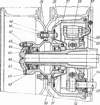
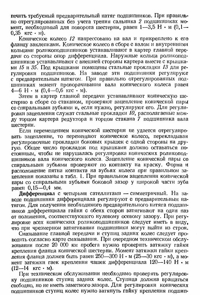
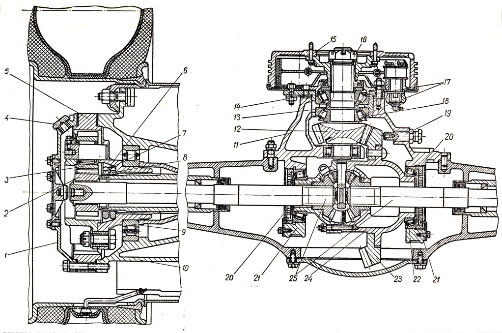
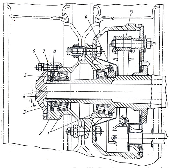
Figure: 1. Rear axle: 1 - gear flange; 2 - oil seal; 3 - cover; 4 - gear washer; 5 - gasket; 6 - front tapered bearing of the bevel gear shaft; 7 - a glass of the bearing of the bevel gear shaft; 8 - adjusting washers of bevel gear shaft bearings; 9 - rear tapered roller bearing of the bevel gear shaft; 10 - gasket for adjusting the meshing of bevel gears; 11 - bevel gear; 12 - bevel wheel; 13 - shims; 14 - right tapered roller bearing intermediate shaft; 15 and 35 - covers, respectively, right and left bearings; 16 - cylindrical gear; 17 - main gear case; 18 - differential bearing cover; 19 - semi-axle wheel support washer; 20 - the right cup of the differential; 21 - cylindrical wheel; 22 - semi-axial gear wheel; 23 - the left cup of the differential; 24 - differential roller bearing ”25 - differential bearing adjusting nut; 26 - brake chamber; 27 - brake shaft with expander fist; 28 - bracket for fastening the brake chamber and expander shaft; 29 - semi-axis; 30 - bridge housing; 31 - satellite with a bronze bushing; 32 - satellite support washer; 33 - crosspiece of satellites; 34 - left tapered roller bearing of the intermediate shaft; 36 - spacer vd-ulka; 37 - brake drum; 38 - hub oil seal; 39 - wheel stud; 40 - nut for fastening the outer wheel; 41 - cap nut for fastening the inner wheel; 42 - oil seal; 43 - lock washer; 44 - wheel bearing nut; 45 - nut pin; 46 - wheel bearing nut; 47 - hole for the axle shaft puller; 48 - hub; 49 - pin; 50 - roller bearing; 51 - oil catcher; 52 - support of the expander; 53 - oiler for lubricating the expander sleeve; 54 - expanding fist; 55 - brake shield; 56 - support; 57 - the axis of the shoe; 58 - brake shoe
The main gear and differential of the hypoid axle are assembled in a separate crankcase (Fig. 43), which, when installed on the axle crankcase, is centered with a landing shoulder. The differential bearing cover rests against the landing collar of the rear wall of the axle housing, thereby increasing the rigidity of the bearings. After disassembling, the covers must be reinstalled in their original places using the pins.
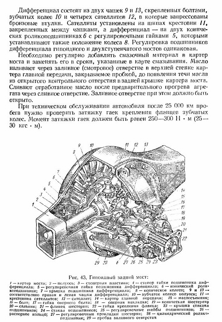
The gear wheel of the glass is installed in two tapered roller bearings in one cylindrical bearing located in the casing of the glazed transmission. Between the spacer ring and the end face of the inner ring of the front tapered roller bearing, there are two shims, the thickness of which is adjusted so that the required bearing preload is ensured. With correctly adjusted bearings, the torque required to rotate the shaft is 2.5-4 Nm (0.25-0.4 kgf-m). Shims are supplied between the bearing cup flange and the main gear housing, the set of which determines the axial arrangement of the gear.
To limit the axial movement of the wheel in the main gear housing, a support bolt is installed, the gap between the ends of the wheel and the support pad should be 0.15-0.20 mm.
In the main gear rear axle an oil scraper is attached to the support pad with two rivets, which removes oil from the wheel end and feeds it into the crankcase pocket, then the oil flows through the channel to the bearings of the gear 19. The oil that gets into the cavity between the outer bearing and the oil seal 20 returns through the channel to the crankcase.
The differential consists of two bolted cups, gears and four satellites, into which bronze bushings are pressed. The satellites are installed on the spikes of the crosses fixed between the cups, and the differential is mounted on two tapered roller bearings 6 with adjusting nuts, which also set the position of the wheel. The adjustment of the differential bearings of the hypoid and two-stage axles is the same.
Must be added regularly lubricant into the axle housing and replace it within the time specified in the lubrication chart. Oil is poured through the filler (inspection) hole in the upper wall of the main gear case, closed with a plug, until oil leaks from the open control hole in the rear cover of the axle case. After preheating the unit, drain the used oil through the drain hole. The filling hole must be open.
When servicing the vehicle after 25,000 km of run, check the tightness of the nuts securing the flanges of the gear wheels. The tightening torque of the nuts should be equal to 250-300 N m (25 - 30 kgf m).
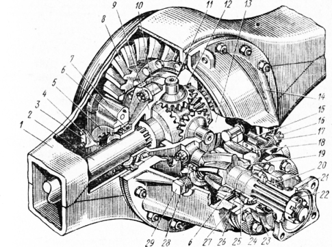
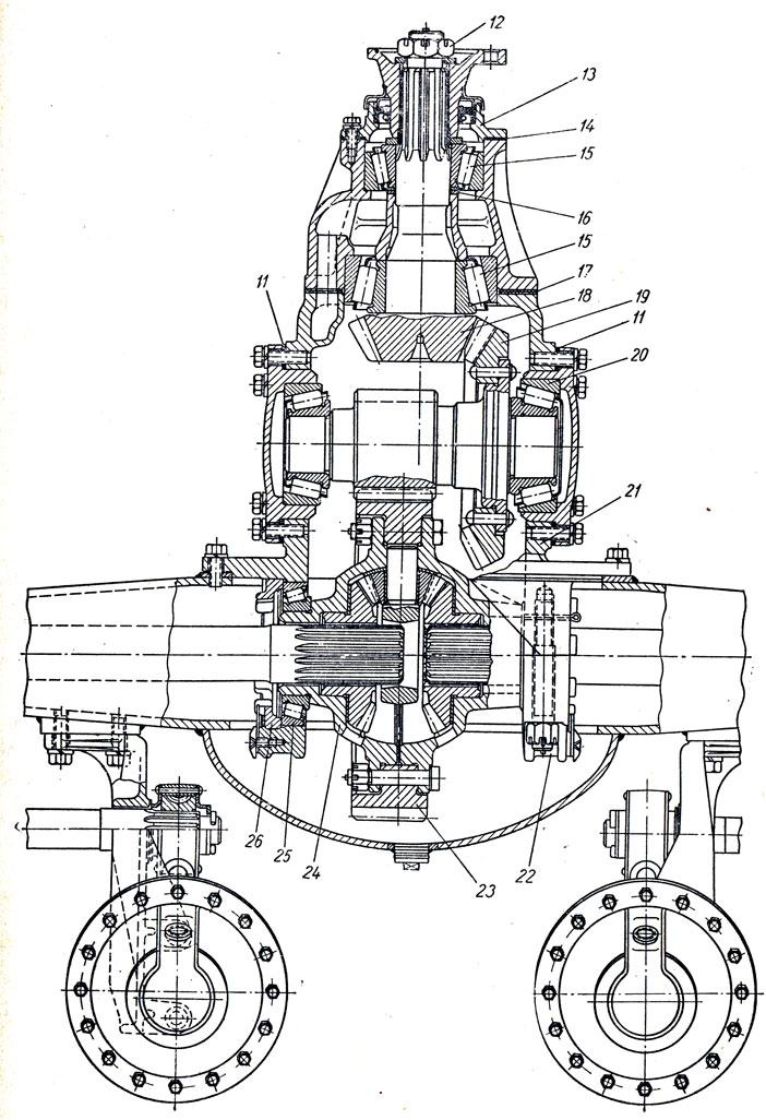
Figure: 2. Hypoid rear axle: 1 - axle housing; 2 - semi-axis; 3 - locking plate; 4 - differential bearing nut stopper; 5 - differential bearing adjusting nut; 6 - tapered roller bearing; 7 - differential bearing cover; 8 - bevel wheel; 9 and 13 - respectively, right and left cups of the differential: 10 - a gear wheel of the semi-axle; 11 - festovina satellites; 12 - satellite; 14 - main gear case; 15 - oil scraper; 16 - bolt; 17 - support bolt nut; 18 - support plate; 19 - bevel gear) oil seal; 21 - gear flange; 22 - flange mounting nut; 23 - glass lid Ba ~ ipnik0v; 24 - Staka. 1 bearings; 25 - bearing adjusting washers; 26 - controversial ring; 27 - gear shims; 28 - cylindrical roller bearing; 29 - filler plug
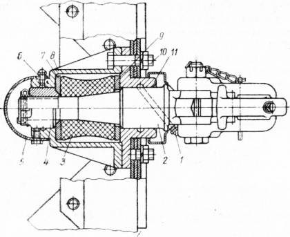
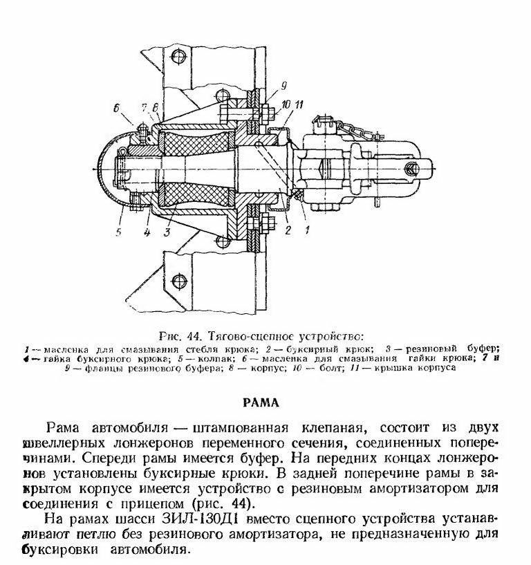
Figure: 3. Towing hitch: 1 - oiler for lubricating the hook stem; 2 - towing hook; 3 - rubber buffer; 4 - towing hook nut; 5 -cap; 6 - oiler for lubricating the hook nut; 7 and 9 - rubber buffer flanges; 8 - case; 10 - bolt; 11 - housing cover
TO Category: - ZIL cars
The main transmission of the rear axles of all modifications of ZIL-130 cars is double, consisting of a pair of bevel gears with spiral teeth and a pair of spur gears with helical teeth. The number of teeth of bevel gears 13 and 25, cylindrical gears 14 and 46. The total gear ratio of the main gear is 6.32.
The leading bevel gear 11 is installed in a glass 7 on two tapered roller bearings. Between the inner rings of the bearings there is a spacer sleeve 33 and two washers 8, which are selected so that when the fastening nut is tightened to failure, the bearings assume the correct working position... At the factory, the pinion pinion bearings are preloaded. With properly adjusted bearings without taking into account the friction of the oil seal 2, the moment required to turn the drive gear is 0.1-0.35 kgf * m.
The driven bevel gear 12 is pressed onto the shaft and riveted to its flange. The driven bevel gear, assembled with the shaft and inner rings of the roller bearings, is installed in the main gear housing from the side of the differential supports, the outer rings of the roller bearings are installed on the outside of the crankcase together with covers 15 and 32. Steel spacers 13 are placed under the covers to adjust the bearings. These bearings are preloaded at the factory.
With correctly adjusted bearings, the torque required to turn the shaft of the driven bevel gear is 0.1-0.35 kgf * m.
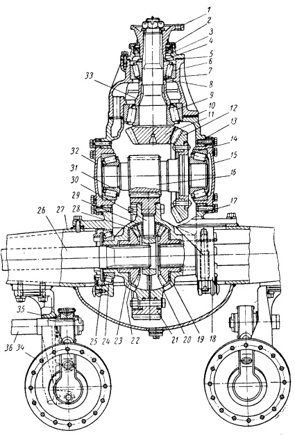
Figure: Rear axle ZIL-130: 1 - driving gear; 2 - oil seal; 3 - cover; 4 - drive gear washer; 5 - gasket; 6 - front roller bearing of the drive bevel gear shaft; 7 - a glass of bearings of the shaft of the driving bevel gear; 8 - adjusting washers of the bearings of the shaft of the driving bevel gear; 9 - rear roller bearing of the drive bevel gear shaft; 10 - gasket for adjusting the meshing of bevel gears; 11 - leading bevel gear; 12 - driven bevel gear; 13 - shims; 14 - right roller bearing of the intermediate shaft; 15 - right bearing cover; 16 - a leading cylindrical gear; 17 - main gear case; 18 - differential bearing cover; 19 - half-axle gear supporting washer; 20 - the right cup of the differential box; 21 - driven cylindrical gear; 22 - half-axle gear; 23 - the left cup of the differential box; 24 - roller bearing of the differential box; 25 - differential bearing adjusting nut; 26 - semi-axis; 27 - bridge housing; 28 - satellite with a bronze bushing; 29 - satellite support washer; 30 - satellite crosspiece; 31 - left bearing of the intermediate shaft; 32 - left bearing cover; 33 - spacer sleeve; 34 - brake chamber; 35 - bracket for fastening the brake chamber and expander shaft; 36 - brake shaft with expander fist; 37 - brake drum; 38 - hub oil seal; 39 - wheel stud; 40 - nut for fastening the outer wheel; 41 - cap nut for fastening the inner wheel; 42 - oil seal; 43 - lock washer; 44 - wheel bearing nut (inner); 45 - nut pin; 46 - wheel bearing nut (outer); 47 - hole for the axle shaft puller; 48 - hub; 49 - pin; 50 - roller bearing; 51 - oil catcher; 52 - support of the expander; 53 - oiler for lubricating the expander sleeve; 54 - expanding fist; 55 - brake shield; 56 - support; 57 - the axis of the shoe; 58 brake pad
Then a leading bevel gear assembly with a glass is installed in the main gear housing, the meshing of the bevel gears with spiral teeth is checked, and, if necessary, it is adjusted.
To adjust the gearing, steel gaskets 10 are used, located between the end of the gearbox housing and the end of the cup 7 of the bearings of the drive gear shaft, by moving the driving bevel gear, it is not possible to adjust the gearing, then the driven bevel gear is moved by shifting the adjusting spacers of the side covers from one side to the other. The total number of shims under the covers must remain constant so that the tapered roller bearing of the driven bevel gear shaft is not disturbed. The meshing of the bevel gears with spiral teeth is checked by contact for paint.
With correct meshing of bevel gears with spiral teeth, the side clearance at the wide part of the tooth is 0.15-0.4 mm.
Differential
Differential with four satellites, symmetrical. The differential bearings are preloaded at the factory.
To obtain the required preload of the differential bearings, the nuts on both sides are tightened one notch from the position corresponding to the zero axial clearance.
When adjusting all tapered roller bearings, keep in mind that if overtightened, the bearings may fail.
Lubrication of the main gear and rear wheel hubs should be done according to the lubrication chart. At the next maintenance service after 20,000 km of run, it is necessary to check the tightening of the nut of the flange of the drive bevel gear and the nuts of the differential cups. The tightening torque of the flange mounting nut should be equal to 20-25 kgf * m, and the tightening torque of the differential cup mounting nuts should be 8-11 kgf * m.
During maintenance it is necessary to check the adjustment of the rear wheel hub bearings.
The hub should rotate freely without noticeable play. To adjust the tapered bearings of the wheel hub, tighten the bearing nut before the hub starts to brake, while turning the hub in both directions so that the rollers are correctly installed on the tapered surfaces of the rings. Then you must loosen the nut about 1/6 of a turn until the nut pin coincides with the nearest hole in the lock washer.
At the end of the adjustment, tighten the lock nut with a wrench until it stops.
It is necessary to periodically flush the breather air passages; clogging them can cause an increase in pressure in the rear axle housing, which can lead to oil leakage.
REAR AXLE ZIL-130REAR AXLE ZIL-130
REAR AXLE ZIL-130
REAR AXLE ZIL-130
REAR AXLE ZIL-130
REAR AXLE ZIL-130
REAR AXLE ZIL-130
REAR AXLE ZIL-130
REAR AXLE ZIL-130
The main gear (Fig. 42) is a two-stage, consists of a pair of bevel gears with spiral teeth and a pair of spur gears with helical teeth (on some cars the main gear is single, hypoid, with a gear ratio of 6.33). The number of teeth of a bevel pair of gears 13 and 25, a cylindrical pair of 14 and 46. The total gear ratio of the main gear is 6.32.
The bevel gear 11 is installed in the glass 7 on two tapered roller bearings. The bevel gear bearings are preloaded at the factory. A spacer sleeve 36 and two shims 8 are installed between the inner rings, the thickness of the set of which is selected in such a way as to provide the required preload of the bearings. With 2 bearings correctly adjusted without taking into account the friction of the oil seal, the moment required to turn the gear is 1-3.5 N "m (0.1-0.35 kgf■ m).
The bevel wheel 12 is pressed onto the shaft and riveted to its flange. The bevel wheel assembly with the shaft and inner rings of the roller bearings is installed in the main gear housing from the side of the differential supports. The outer rings of the roller bearings are installed on the outside of the crankcase together with the covers 15 and 35. Steel spacers 13 are placed under the covers to adjust the bearings. These bearings are preloaded at the factory. With correctly adjusted bearings, the torque of the bevel wheel shaft is 4-6 N m (0.4-0.6 kgf m).
Then, a bevel gear assembly with a glass is installed in the main gear case, the engagement of the bevel pair with spiral teeth is checked and, if necessary, it is adjusted. To adjust the gearing, steel gaskets 10 are used, located between the end of the gearbox housing and the end of the sleeve 7 of the pinion shaft bearing.
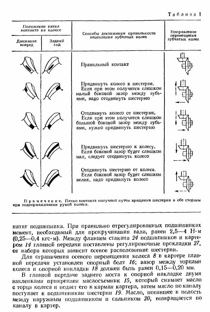
If it is not possible to adjust the engagement by moving the bevel gear, then move the bevel wheel by shifting the adjusting shims of the side covers from one side to the other. The total number of gaskets under the covers must remain constant so that the adjustment of the tapered roller bearings of the bevel gear shaft is not disturbed. The engagement of the tapered pair with the spiral teeth is checked by contact with the paint. The shape and location of the contact patch on the teeth of the wheel with correct engagement are shown in table. 1. With the correct engagement of the bevel pair with spiral teeth, the lateral clearance at the wide part of the tooth is 0.15-0.4 mm.
The differential with four satellites is symmetrical. The differential bearings are preloaded at the factory. To obtain the required preload of the differential bearings, the nuts on both sides are tightened one notch from the position corresponding to the zero axial clearance. When adjusting all tapered roller bearings, keep in mind that if overtightened, the bearings may fail.
Lubrication of the main gear and rear wheel hubs should be carried out according to the lubrication chart. At the next maintenance service after 20,000 km of run, it is necessary to check the tightening of the nut of the bevel gear flange. The tightening torque of the flange mounting nut should be equal to 250-300 N m (25-30 kgf m), and the tightening torque of the nuts for fastening the differential cups should be 120-140 N m (12-14 kgf m).
During maintenance it is necessary to check the adjustment of the rear wheel hub bearings. The hub should rotate freely without noticeable play. To adjust the tapered bearings of the wheel hubs, tighten the bearing retaining nut (the tightening torque is 60-80 N * m (6-8 kgf-m) 3, turning the hub in both directions to prevent skewing of the rollers, and then unscrew the nut approximately 120 "( 1/3 turn) Check the axial play in the hub bearings Install the lock washer by aligning the pin of the nut with the nearest hole in the lock washer and pull out the lock nut [pulling torque is 250-300 Nm (25-30 kg / m) 1. The hub must rotate freely and not have a noticeable (more than 0.15 mm) axial clearance. It is necessary to periodically flush the breather air passages, if they become clogged, the pressure in the rear axle housing may increase, which can lead to oil leakage.
Figure: 42. Rear axle.
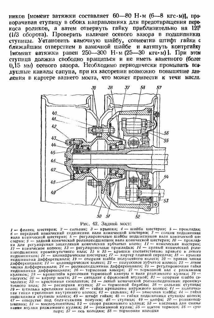
The main gear and differential of the hypoid axle are assembled in a separate crankcase 14 (Fig. 43), which, when installed on the axle crankcase, is centered with a landing shoulder. Cover 7 of the differential bearing abuts against the landing collar of the rear wall of the crankcase 1
Bridge, thereby increasing the rigidity of the supports. After disassembling, the covers must be reinstalled in their original places using the pins.
The gear 19 of the cup 24 is installed in two tapered roller bearings 6 and in one cylindrical bearing 2S located in the main gear housing. Between the spacer ring 26 and the end face of the inner ring of the front tapered roller bearing, two shims 25 are located, the thickness of which is selected so that the required preliminary
Table 1
Direction of movement of gear wheels
Reverse
Position of the contact patch on the wheel
Progress
Methods for Delivering Correct Gear Meshing
Correct contact
Slide the wheel towards the gear. If this results in too little lateral clearance between the teeth, it is necessary to move the gear
Move the wheel away from the gear. If this results in too large a lateral clearance between the teeth, you need to move the gear
Move the gear to the wheel. If the side clearance is too small, move the wheel
Move the gear away from the wheel. If the side clearance is too large, you need to move the wheel
Note. The contact patch is obtained by rotating the gear in both directions while braking the wheel by hand.
bearing preload. With correctly adjusted bearings, the torque required to rotate the shaft is 2.5-4 Nm (0.25-0.4 kgf-m). Between the flange of the cup 24 of the bearings and the crankcase 14 of the main gear, shims 27 are supplied, the set of which determines the axial arrangement of the gear.
To limit the axial movement of the wheel 8, a support bolt 1b is installed in the main gear housing, the gap between the ends of the wheel and the support pad 18 should be 0.15-0.20 mm.
In the main gear of the rear axle, an oil scraper 15 is attached to the support pad with two rivets, which removes oil from the end of the wheel and feeds it into the crankcase pocket, then the oil flows through the channel to the bearings of the gear 19. The oil that has got into the cavity between the outer bearing and the oil seal 20 is returned through the channel to the crankcase.
The differential consists of two cups 9 and 13, bolted together, gears 10 and four satellites 12, into which bronze bushings are pressed. The satellites are installed on the spikes of the I crosses, fixed between the cups, and the differential - on two tapered roller bearings b with adjusting nuts 5, which also set the position of the wheel 8. Adjustment of the differential bearings of the hypoid and two-stage axles is the same.
It is necessary to regularly add lubricant to the axle housing and replace it at the time indicated in the lubrication chart. Oil is poured through the filler (inspection) hole in the upper wall of the main gear case, closed with a plug, until oil leaks from the open control hole in the rear cover of the axle case. After preheating the unit, drain the used oil through the drain hole. The filling hole must be open.
When servicing the car after 25,000 km of run, it is necessary to check the tightening of the nuts for fastening the flanges of the gear wheels. The tightening torque of the nuts should be equal to 250-300 I m (25 - 30 kgf m).
Figure: 43. Hypoid rear axle:
"- axle housing; 2- axle shaft; 3 - locking plate - differential bearing nut stopper; 5 - differential bearing adjusting nut; 6 - tapered roller bearing; 7 - differential bearing cover; 8 - bevel wheel; 9 and 13 - right and left, respectively differential cups; 10 - semi-axle gear wheel; H - cross of satellites: 12 - satellite; 14 - main gear case; 15 - oil scraper; 16 - bolt; 17 - support bolt nut; 18 - support pad: 19-bevel gear) 20 - oil seal; 21 - gear flange: 22 - flange mounting nut; 23 - bearing cup cover; 24 - stack of 1 bearings; 25 - bearing shims; 26 - spacer ring; 27 - gear shims; 28 - cylindrical roller bearing; 29 - filler plug
Figure: 44. Trailer coupling:Cardan transmission ZIL-130
On modern cars and trucks (Volga, GAZ-53A, GAZ-66 and others), hypoid main gears are increasingly used, and on heavy-duty trucks (MAZ-500, MAZ-503, MAZ-504), a spaced main broadcast.
In the hypoid main gear, the axis of the drive gear 14 is displaced downward relative to the axis of the driven gear 1 (Fig. 131). This lowers the vehicle's center of gravity and improves stability. For the same durability, the hypoid gear is smaller than the conventional bevel gear. But the hypoid transmission has a slightly lower efficiency and, in addition, a special oil is used for it.
In a spaced-apart final drive, the initial reduction in RPM is performed using a pair of bevel gears of the final drive, and the final reduction in rotation speed and an increase in torque is performed using the wheel planetary gearsmounted in the hubs of 10 wheels (Fig. 132).
This arrangement makes it possible to reduce the dimensions of the first pair of the final drive, differential and axle shafts due to the reduction of the loads on the parts of these devices.
On trucks GAZ-53A and GAZ-66, which do not have a centralized tire inflation system, there are no oil seals at the inner ends of the axle shafts. Therefore, lubrication of the wheel hub bearings is carried out with the help of oil supplied to them from the final drive housing, which simplifies their maintenance.
The use of a cam differential 2 (see Fig. 131) of increased friction on the GAZ-66 car significantly improves the cross-country ability of this car. Blocking factor- the ratio of the tractive effort of the non-skid wheel to the total effort on the skidding and non-skid wheels - for the cam differential is 0.8, and for the gear differential - 0.55. Tests have shown that replacing a conventional limited slip differential with a limited slip differential doubles the pulling force on the hook of a vehicle moving along slippery roadif one of the drive wheels is slipping.
During operation, the gears of the main drive wear out, and if the gearing of the gears is broken and there is no lubrication, the teeth may break. The meshing of the gear teeth is disrupted as a result of bearing wear and elastic deformation of the shafts when they are overloaded.
Maintenance of final drives should ensure normal work without increased noise of gears and significant heating of the crankcase (oil temperature should not exceed 60 ° C). When starting off and when driving by inertia, no knocks should appear in the drive axle. Oil leakage, which can occur due to leaks in plugs, oil seals, connector gaskets and blockage of breathers, is not allowed.
Under operating conditions, during routine maintenance, tighten fasteners, adjust tapered roller bearings and lubricate; in repair shops, the relative position of the bevel gears is adjusted.
With TO-1, check the fastening of the crankcase 21 (Fig. 133), the gearbox and the side bearing caps 20 on the ZIL-130 car, the tightening of the nuts 6, the axle shafts 4 to the hubs of the 2 wheels, the tightness and condition of the axle housing, as well as the oil level in the crankcase ... If necessary, add oil to the level of the control plug on all vehicles.
Hypoid final drive trucks GAS can only be lubricated with TS-14.5 oil with an additive Chloref 40 (TU TNZ - 128-63). The use of other oils used for lubrication of final drives, including high quality transmission oils with additives and hypoid oil according to GOST 4003-53, intended for passenger cars, unacceptable, as this will lead to rapid wear and breakage of the gear teeth. On vehicles ZIL-130 and ZIL-131, the oil used to lubricate the gearbox is filled into the main gearboxes.
Transmission oil (nigrol) is poured into the crankcase 11 (Fig. 132) of the main gear and the gearbox of the wheel drive of the MAZ-500 car. The oil is poured into the gearbox through the filler hole in the cover 1, closed with a plug 4. In this case, the drive 2 and driven 5 gears and satellites 3 of the wheel gear reducer are lubricated.
With TO-2, the condition of the breathers of the axle housing is additionally checked and the bolts of the gearbox fastening to the rear axle beam are tightened; on GAZ-53A and GAZ-66 cars, tighten the bearing clutch bolts of the drive gear, and on the ZIL-130 they attach cover 13 (see Fig. 133) of the front bearings of the drive bevel gear and check its gasket 14.
After one TO-2, the gearbox is removed on the ZIL-130 car, the fastening of the driven cylindrical gear 23 and the tightening of the differential bearing caps 25 are checked, and on the GAZ-53A and GAZ-66 the tightening of the drive gear flange nut is checked. Oil is changed in the drive axle housings of the GAZ-53A, GAZ-66 ZIL-130, MAZ-500, Volga vehicles.
Through one TO-2, the condition and tightness of the tapered roller bearings of the wheel hubs is also checked. At the same time, they thoroughly rinse in gasoline and inspect roller bearings 3 (see Fig. 130) of the hubs of the front driving wheels and roller bearings 1 (see Fig. 133) of the rear driving wheels. The bearing is replaced when corrosive (patchy) wear or parts chipping occurs. Next, the condition of the seals 8 and 9 of the bearings is checked, the hubs of the front and rear driving wheels of the GAZ-66, which have centralized tire inflation, refractory grease-at 1-13s or YANZ-2, are placed in the rear wheel hubs of ZIL-130 cars. As noted above, the bearings of the drive wheel hubs of the GAZ-53A and GAZ-66 cars, which do not have centralized tire inflation, are lubricated with oil flowing from the main gear. Therefore, when filling it into the axle crankcase, it is necessary to alternately raise each wheel by at least 200 mm to fill the wheel hub with oil.
To adjust bearings 1 (see Fig. 133), raise the axle with a jack so that the tire does not touch the ground. Then take out the axle shaft 4, unscrew the lock nut 5, remove the lock ring 7 and the outer oil seal 8, by 1/2 - 1/3 turn, unscrew the adjusting nut 5 to check if the wheel rotates freely. If free rotation is interfered with brake pad 10 or seizure of oil seals 8 and 9, then these malfunctions must be eliminated. After that, the adjusting nut 3 is tightened until the wheel rotates tightly on the bearings. When tightening the nut, turn the wheel to ensure that the rollers are evenly positioned in the bearings. The bearings are tightened correctly if the wheel comes to a stop immediately after being pushed. Further, the adjusting nut is torn off for ZIL-130 cars by 1/6 of a turn, for GAZ-53A GAZ-66 by 1/8 of a turn and fixed with a lock washer and a locknut. After correct bearing adjustment, the wheel should rotate freely, without noticeable heaving and axial movement.
Bearings 9 (see Fig. 132) of the hub 10 of the MAZ-500 drive wheel are lubricated with oil filled in to lubricate the gears of the wheel drive reducer. Adjustment of the bearing tightening is carried out with a nut 8, which is locked with a washer 7 and a lock nut 6.
In order to increase the service life of the gears of the hypoid final drive, it is necessary to systematically monitor and adjust the installation of tapered bearings 9 (see Fig. 131). Adjustment of the tightening of the bearings of the hypoid drive gear is made only if the axial clearance of the gear is greater than 0.03 mm .
This gap is measured by the indicator with disconnected cardan shaft or by swinging the flange by hand. In order to remove the coupling 8 with the drive shaft 11, it is necessary to pull out the axle shafts 6 and 17, remove the gearbox housing 15 assembly, unscrew the screw 7 of the driven gear stop and remove the oil pipe, unscrew the nuts 5 of the differential bearings, remove the bearing caps 16 and take out the differential 18 Next, unscrew the bolts securing the clutch 8 to the crankcase 15 of the gearbox. The clutch is installed in a locksmith's vice and without disassembling it, check whether the total thickness of the shims 12 is sufficient. For this, the nut 10 of the shaft 11 of the drive gear is unpinned and screwed to failure. If there are not enough shims, then the pinion gear will turn with great resistance. In this case, the adjustment is reduced to correct selection the total thickness of the spacers by removing or adding them. Their total number is changed by one or two so that the bearings have a slight interference fit.
For checking, the coupling is assembled and installed in a vice, but without the gland and cover. The pinion shaft nut is tightened to failure, and one of its slots must coincide with the hole in the shaft for the cotter pin (it is impossible to unscrew the nut in order to match the slot and the hole). With correctly adjusted bearing tightening, the torque for turning the pinion gear (with the oil seal removed) should be 58.8399 - 137.293 Nm (6 - 14 kGm).
Differential box bearings 3 are usually adjusted during repair. In this case, with the help of nuts 5, the lateral clearance and the contact in the engagement of the gears 14 and 1 are adjusted. For this, a small lateral clearance is initially set in the engagement of the gears. Then, having previously removed the lock plates 4, the nuts 5 are screwed in until they come into contact with the outer rings of the differential bearings. Next, the nuts are alternately tightened until a slight tightening of the bearings is obtained, but with maintaining a gap in the meshing of the gears. At the same time, the driven gear 1 is turned in order for the bearing rollers to occupy correct position... After that, the nuts 5 are released, then screwed again until they come into contact with the bearings, and then they are set in such a position that the bearings do not have tightening and axial movement. Bearing adjustment ends by tightening each nut one notch to pre-tighten.
The side play of the gear teeth is checked with an indicator at four evenly spaced points. To increase the lateral clearance, release the nut from the side of the driven gear. To maintain the tightness of the differential bearings, the opposite nut is tightened the same number of notches as the driven gear nut was loosened.
The clearance of the gears of one axle should not change by more than 0.1 mm ... To ensure that the nut 5 comes into contact with the bearing ring 3 and to avoid displacement of the ring during operation, after unscrewing the nuts 5, screw them back in. So, for example, if it is required to loosen the nut by one notch, then it should be released by two notches, and then tightened by one.
The adjustment of the meshing of the bevel gears of the main drive should be carried out by qualified workers using precise measuring instruments and checking for paint on the contact patch. The dimensions of the side clearances should be maintained in accordance with the data of the factories.
To check the engagement by the contact patch, the teeth of the driving punch are covered with a thin layer of paint. The driven gear is lubricated to check the engagement under light load, and the drive gear turns in both directions.
When correct adjustment the position of the gear, the contact spot should be located in the middle part of the tooth both in the axial, to and in the radial directions, which is ensured by the selection of shims 13.
If the contact patch is located closer to the large end of the tooth (in the axial direction), it is necessary to move the driven gear towards the driving gear. If this results in a too small clearance between the teeth, then the pinion must be moved to the appropriate distance. When the spot is located closer to the small end of the tooth (in the axial direction), it is necessary to move the drive gear away from the driven gear. A decrease in the side clearance is achieved by approaching the pinion gear.
When the spot is located at the tooth apex (in the radial directions), the drive gear must be moved to the driven gear. Insufficient lateral clearance is ensured by a corresponding movement of the driven gear.
If the stain is located at the base of the tooth, then it is necessary to move the drive gear away from the driven gear. If the side clearance between the teeth is too large, then the driven gear must be moved.
For ZIL-130 cars after a run of 20,000 km at the next maintenance check the tightening of the nut 12 for fastening the flange of the shaft of the driving bevel gear and nuts 26 for fastening the bearings 25, differential cups 24. For this, respectively, apply the moments: 196.133 - 245.166 Nm 0 - 25 kGm) and 78.4532 - 107.873 nm (8 - 11 kGm).
The tightening of the tapered roller bearings 15 is adjusted by changing the thickness of the shims 16. The tightening is checked by applying a torque of 0.980665 - 3.43233 Nm (0.1 - 0.35 kGm) to the shaft flange of the drive gear 18 with the oil seal of the shaft cover 13 removed.
The tightening of the tapered roller bearings 20 of the intermediate shaft of the main gear is controlled by changing the total thickness and rearranging the spacers 11 under the bearing caps.
The meshing of the bevel gears of the main gear is regulated by changing the total thickness of the gaskets 17 installed between the bearing sleeve 15 and the crankcase 21 of the main gear. If at the same time it is not possible to adjust the engagement of the bevel gears, then the spacers 11 are rearranged from one side to the other without changing their number.
Main gear ZIL-130 chassis (Fig. 42) - two-stage, consists of a pair of bevel gears with helical teeth and a pair of spur gears with helical teeth (on some cars, the main gear is single, hypoid, with a gear ratio of 6.33). The number of teeth of a bevel pair of gears 13 and 25, a cylindrical pair of 14 and 46. The total gear ratio of the main gear is 6.32.
The bevel gear 11 is installed in the glass 7 on two tapered roller bearings. The bevel gear bearings are preloaded at the factory. A spacer sleeve 36 and two adjusting washers 8 are installed between the inner rings, the thickness of the set of which is selected so as to provide the required preload of the bearings. With 2 bearings correctly adjusted without taking into account the friction of the oil seal, the torque required to turn the gear is 1-3.5 N * m (0.1-0.35 kgf * m).
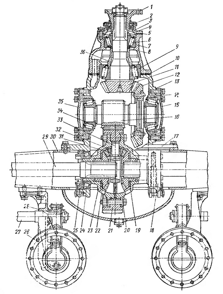
Figure: 42. Rear axle ZIL-130:
1 - gear flange; 2 - oil seal; 3 - cover; 4 - gear washer; 5 - gasket; 6 - front tapered bearing of the bevel gear shaft; 7 - a glass of the bearing of the bevel gear shaft; 8 - adjusting washers of bevel gear shaft bearings; 9 - rear tapered roller bearing of the bevel gear shaft; 10 - gasket for adjusting the meshing of bevel gears; 11 - bevel gear; 12- bevel wheel; 13 - shims; 14 - right tapered roller bearing of the intermediate shaft; 15 and 35 - covers, respectively, right and left bearings; 16 - cylindrical gear; 17 - main gear case; 18 - differential bearing cover; 19 - support washer of the semi-axle wheel of the rear axle ZIL-130; 20 - the right cup of the differential; 21 - cylindrical wheel; 22 - semi-axial gear wheel; 23 - the left cup of the differential; 24 - differential roller bearing; 25 - differential bearing adjusting nut; 26 - brake chamber; 27 - brake shaft with expander fist; 21 - bracket for fastening the brake chamber and expander shaft; 29 - semi-axis; 30 - bridge housing; 31 - satellite with a bronze bushing; 32 - satellite support washer; 33 - crosspiece of satellites; 34 - left tapered roller bearing of the intermediate shaft; 36 - spacer sleeve; 37 - brake drum; 38 - hub oil seal; 39 - wheel stud; 40 - nut for fastening the outer wheel; 41 - cap nut for fastening the inner wheel; 42 - rear axle oil seal ZIL-130; 43 - lock washer; 44 - wheel bearing nut; 45 - nut pin; 46 - wheel bearing nut; 47 - hole for the axle shaft puller; 48 - hub; 49 - pin; 50 - roller bearing; 51 - oil catcher; 52 - expansion fist support; 53 - oiler for lubricating the expander sleeve; 54 - expanding fist; 55 - brake shield; 50 - support; 57 - axis of the shoe; 58 - brake shoe.
The conical wheel 12 of the rear axle ZIL-130 is pressed onto the shaft and riveted to its flange. The bevel gear assembly with the shaft and inner rings of the roller bearings is installed in the main gear housing from the side of the differential supports. The outer rings of the roller bearings are installed on the outside of the crankcase together with the covers 15 and 35. Steel spacers 13 are placed under the covers to adjust the bearings. These bearings are preloaded at the factory. With correctly adjusted bearings, the torque of the bevel wheel shaft is 4-6 N m (0.4-0.6 kgf m).
Then, a bevel gear assembly with a glass is installed in the crankcase of the main gear ZIL-130, the engagement of the bevel pair with spiral teeth is checked and, if necessary, it is adjusted. To adjust the gearing, steel gaskets 10 are used, located between the end of the gearbox housing and the end of the sleeve 7 of the pinion shaft bearing.
If it is not possible to adjust the engagement by moving the bevel gear of the rear axle ZIL-130, then move the bevel wheel, shifting the adjusting shims of the side covers from one side to the other. The total number of gaskets under the covers must remain constant so that the adjustment of the tapered roller bearings of the bevel gear shaft is not disturbed. The engagement of the tapered pair with the spiral teeth is checked by contact with the paint. The shape and location of the contact patch on the teeth of the wheel with correct engagement are shown in table. 1. With the correct engagement of the bevel pair with spiral teeth, the lateral clearance at the wide part of the tooth is 0.15-0.4 mm.