The shaft is a detail of machines and mechanisms intended for transmitting torque along its longitudinal axis. Most often there are shafts assembly with the impellers installed on them, pulleys, asterisks, etc.
Like any other mechanical detail, the shaft may be incorrectly installed in bearing supports, have inhomogeneities in the density of material, disorders in the manufacture of manufacturing geometry and not enough to fit the parts rotating with it, etc. As a result of the above reasons, unbalanced masses appear in the rotating shaft. causing low-frequency vibrations of the shaft. These vibrations can be so significant that they can lead to the bending of the shaft and complete destruction. bearing nodes and other parts of the car. That is why it is so important to balance the effect of unbalanced by the masses of the shaft balancing procedure.
Earlier, we have already considered the types of non-unquestion of the rotor and the appropriate types of balancing - static and dynamic. It was noted that the accuracy of dynamic balancing an order of magnitude higher than the accuracy of static balancing, and that for the rotors whose diameter is significantly longer (pulleys, working wheels, asterisks), it can be limited to the implementation of static balancing.
As applied to the case of shafts in the collection (for example, a shaft with an impeller) in most cases, it is possible to limit the static balancing of the impeller and the dynamic shaft balancing assembly on the machine and / or in its own supports. In fact, the perfectly balanced shaft assembly is a shaft with separately balanced items, then balanced assembly on the machine, and finally balanced in its own supports.
As the statistics of the company "Balti" - a recognized expert in the field of balancing, - proper balancing of the shafts of rotating machines by 23% -100% increases the service life of impellers and working wheels, and also by 10% -25% increases their useful power.
Balancing of shafts in own supports must be entrusted to the specialists of the Balti technical service, the armed up-to-date balancing tools - mobile sets of Proton-Balance-II and Baltech VP-3470 and the Baltech-Balance Last Space Balance Programs.
The main production area of \u200b\u200bthe company "Balti" is the production of modern degenerase machines of horizontal, vertical and automatic type for rotors of various configurations, weight and dimensions. Consider in more detail the possibilities of Baltech balancing machines using the example of the VBM-7200 series vertical balancing machine.
Balance machines of the Baltech VBM-7200 series are designed for single-position or two-plane balancing of shafts and parts (operating wheels, pulleys, discs, etc.) without shaft neck. With regard to our case balancing of shafts, the data of the machines also carry out balancing cutting tool and cartridges.
The shaft balancing procedure takes only a few minutes and includes:
- Input of the geometric parameters of the balancing shaft;
- Run a balanced shaft into rotation and removal of automatically calculated data in size and angle of adjusting the corrective mass.
- Installation / removal of the corrective mass.
Especially note that high speed And the accuracy of measurements is achieved through the use of the Baltech-Balance program, the standard functionality of which is allowed to conduct multi-block (up to 4-planes) and multipoint (up to 16 points) balancing with amplitude measurement devices and vibration phases of any manufacturers.
To get deep theoretical knowledge and professionally master the skills of working with balancing machines and "Balti" devices, we recommend that you sign up for the nearest course of Tor-102 "Dynamic balancing" in Training Center Companies Baltech.
It happens that on the engine you need to replace the flywheel, its toothed crown or the clutch basket and after replacing the listed parts, and even after the replacement (after washing oil canals), it must be defined. If you neglect this operation, then your engine, even with an increase in the velocity of the machine, only up to 70 km / h, will begin to vibrate severely because of the imbalance. Naturally, it is impossible to allow, and crankshaft, Before installing it on the engine, you need to be balanced. How to make a simple device for balancing in just a couple of hours, and that we will need and consider in this article.
Most automotive or motorcycle plants balance their crankshafts assembled with the flywheel and the clutch basket, and some, for example, the crankshaft of the Dnieper motorcycle or car Zaporozhets, balanced also assembled with the centrifuge. It must be taken into account and to wear all the details on the crankshaft before balancing, and even pulley or gear on the front of the shaft, unless of course they exist in the design of your engine.
Well, naturally all connecting rods assembled with pistons, rings and fingers, you will need to weigh and achieve their absolutely identical weight. Many plants (as a rule, domestic) neglect by this, so I advise it during the first repair of the engine, be sure to weigh the above items and if there is a difference in weight, eliminate it (removal of excess metal).
By the way, when the engine is booming, many mechanics facilitate the flywheel with his sharpening, and after facilitating the flywheel, it is also necessary to make the knee-balancing, assembled with a lightweight flywheel.
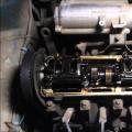
Device for balancing crankshaft.
A device for balancing, which will be described in this article (see photo), is very simple and made anything, not even experienced in the driver's locksmiths. To work, you will need a little profile pipe, or angle, steel bar with a diameter of 12 - 16 mm, (can be construction), Bulgarian and.
First, it will be necessary to make the basis - the frame, the size of about 400 x 400 or 500 x 500 mm, which is welded from angle or profile tube (width of angle or pipe 45 - 60 mm). In general, the dimensions of the frame and the device itself depend on the length of your crankshaft, because if you need to delete the crankshaft from the truck, then naturally this device will need to make more sizes.
After you boil the frame and clean the welds, in two corners of the frame (numbers 1 and 2 in the photo) and in the middle of the opposite pipe (figure 3 in the photo) you will need to drill holes (the diameter depends on the rod thickness from which they are made Studs). Nuts are welded on top of the top, the diameter of the internal thread of which depends on the diameter of the three studs that you buy or make from the bar.
Why are there three studs, and not four in every corner of the frame? Because to set the frame before balancing strictly horizontally (using a level), it suffices to twist just three studs, and the fourth only complicates the adjustment. For each stud will need to turn back also the lock nuts, which, after adjusting the frame, is touched. At the top of each heel, it is useful to apply the grinder of two lys for a wrench so that then it was easy to twist them, when adjusting the level.
Now it will be necessary to drill four holes closer to each corner of the frame, with a diameter of 14 - 16 mm. These holes are inserted and pinched with nuts 4 studs (racks) made from a bar, a thickness of about 14 - 16 mm, and a dina of about 250 mm (the length of all four studs is absolutely the same).
Now on the upper part of each pair of racks, you need to wear two corners (20-40 mm wide and about 300 mm long) corner, (before this in the corners drill holes). Corners wear and grab the welding so that their acute edge turns out to be at the top, the crankshaft will be laid on this edge. It turns out opposite each other located two P-shaped racks (like two horizons). That's all - a device for balancing the crankshaft in garage or even home is ready!
Balancing crankshaft.
Before balancing, you first need to set the device strictly horizontally, relative to the force of attraction of the Earth. To do this, first put the level of the corner (20 mm) of the P-shaped rack, located near the numbers 1 and 2 and twist the studs 1 and 2 until the absolutely horizontal location and, respectively, the corner on which it lies.
Then we turn the level perpendicularly and put the level of the cross, that is, immediately into two corners of both P-shaped racks, and we achieve the rotation of the hairpin 3, the absolutely horizontal position of the entire device as a whole.
Having putting the device accurately horizontally, you can lay the crankshaft on it assembled with the details as in the photo. If there is an imbalance, then the crankshaft will immediately start turning, that is, roll over the edge of the corners until the center of the severity of the parts is at the lowest point (the Earth's attraction helps us). Naturally, this imbalance (advantage) needs to be eliminated.
To eliminate the advant, you need in the most severe (bottom - on the photo indicated by the arrow) parts of the flywheel drill excess metal to remove excess weight. But how to find out exactly this weight. To do this, to the easiest opposite side of the flywheel (at the top) you need to glue the magnets of different weights or pieces of a large magnet (you can break into the pieces of a magnet from the speaker).
It will be necessary to add (glued) magnets to the flywheel until the crankshaft assembly with the details, no matter how you turn it on the corners, must lie still (do not roll in the right or left). All magnets that were glued, you need to weigh, and this accurate weight and will be a translate (imbalance). Now on sale full of Chinese electronic scales - they will need to buy, they are not expensive (or ask to weigh the magnets in the store).
Now it will be necessary to drill with the flywheel so much metal so that the weight of the chips is the same as the weight of the magnets that compensated for the imbalance. When driving, it is desirable to lay the fabric under the flywheel so that you can collect chips and weighed. But almost one hole drilling (approximately 7 - 8 mm) is always missing, and you have to drill a few. If there is a milling machine, then you can feed extra metal in the flywheel. But the main thing is not to overdo it in this matter, and then you will have to drill on the opposite side of the flywheel.
 By the way, if you have a pulley, a gear or centrifuge on the other end of the crankshaft, and you changed them and not flywheel, then you will need to balance along with these details (as in the photo) and drill extra metal in them, and not in the flywheel. Well, if you change the clutch basket, you need to balancing your crankshaft with a basket fixed on the flywheel (excess metal can be drilled here in a basket, where the holes are for its fastening).
Well, finally, I will add that this device can be used to check the knee beyon, using an indicator rack from a clockwise type. To do this, you will only need to drill two holes in the upper corners (which the crankshaft is stacked) and consolidate two prisms on them, to which the crankshaft will later be laid, to test it with a clock indicator.
I hope this article will help all drivers who love to do everything on their car themselves, and which with the help of this device will be able to easily delete the crankshaft in his garage.
For completeness of the picture, as well as everyone understands how the balancing of the crankshers of any engine affects the softness of its work, look at the video below; Successes to everyone!
The balancing of the crankshaft at home may be needed to those who really want to fully recognize their car and does not trust specialists to a hundred. Below will be considered all the nuances associated with this issue.
Why do you need balancing crankshaft?
What about the causes of such behavior, so there may be several. Among them, it is impossible to exclude possible errors made during the manufacture of conjugate parts. In addition, the inefficiency of materials, of which the elements of the crankshaft are made. Increased gaps in conjugate assemblies, their inconsistency, poor-quality installation and, of course, are not sufficiently accurate centering.
And do not forget about the natural wear, which has never played a positive role.
Where to delete the crankshaft - repair options
There are two ways how to delete crankshaft. The first is static, it is less accurate. In this case, special knives are used to which the part is set. And the imbalance is determined by its position during rotation. If the upper part of the crankshaft is lighter than the lower, the weights are fixed on it and they produce such measurements and a fitting to reach equilibrium. And only after that, on the opposite side, the holes for the counterweight are dried.
Second view - dynamic balancing . It requires special equipment for its implementation. The crankshaft is installed in the floating bed and is spinning to the desired revolutions. The light beam finds and scans the most difficult point that provokes shaking, and displays it on the screen. And to achieve a balance, it remains for small - remove overweight from it.
Balancing crankshaft at home
Basically, at home the kneel balancing with the flywheel is carried out.. To do this, it is also necessary to determine the hardest point. This is done as follows: two T-shaped plates are installed, naturally in terms of level, and on top there is a detail on them. In the case of imbalance, the crankshaft will roll until its most severe point is in the lower position. Thus, the place is determined from which it is necessary to remove some metal. Repeat this procedure should be reached in full equilibrium.

Unfortunately, the problems of balancing the crankshaft (flywheel, clutch baskets, dampers) are practically uncovered in affordable literature, and if anything can be found, then these are GOST and scientific literature. However, understanding and understanding what is written there requires a certain preparation and presence of the most balancing machine. This, of course, beat off the car mechanic every desire to deal with these issues from the point of view. repair of DVS. In this short article, we will try to reveal the problems of balancing from the position of an auto mechanic, without going into complex mathematical calculations and more focusing on practical experience.
So, the most frequent question occurring when repairing the engine: Do I need to carry out balancing after grinding the crankshaft?
To do this, we will show all the stages of the balancing of the crankshaft, which are performed in our company when repairing the crankshaft. As an example, take the crankshaft of the engine MV 603.973. It's inline 6 cylinder diesel engine. The permissible imbalance of the manufacturer's plant on this shaft is 100 GMM. Is there a lot or a little? What will happen if the imbalance is less or more this number? We will not consider these questions in this article, but we will describe them later. But it is safe to say that the manufacturer's factory takes these numbers not from the ceiling, but conducts a sufficient number of experiments in order to find a compromise between the allowable imbalance value for the normal operation of the engine and the cost of production to ensure this tolerance. Just for comparison, the allowable imbalance of the manufacturer on the crankshaft engine ZMZ. 406 360 GMM. To make it easier to imagine and understand these numbers, remember a simple formula from the course of physics. For rotational motion, the power of inertia is equal to:
m. - unbalanced mass, kg;
r. - radius of its rotation, m;
w. – angular velocity rotation, rad / s;
n. - Rotation frequency, rpm.
So, we substitute the numbers in the formula and accept the speed of rotation from 1000 to 10,000 rpm, we obtain the following:
F1000 \u003d 0.1x 0.001x (3.14x1000 / 30) 2 \u003d 1.1
F2000 \u003d 0.1x 0.001x (3.14x2000 / 30) 2 \u003d 4.4
F3000 \u003d 0.1x 0.001x (3.14x3000 / 30) 2 \u003d 9.9 n
F4000 \u003d 0.1x 0.001x (3.14x4000 / 30) 2 \u003d 17.55 N
F5000 \u003d 0.1x 0.001x (3.14x5000 / 30) 2 \u003d 27.4
F6000 \u003d 0.1x 0.001x (3.14x6000 / 30) 2 \u003d 39.5
F7000 \u003d 0.1x 0.001x (3.14x7000 / 30) 2 \u003d 53.8
F8000 \u003d 0.1x 0.001x (3.14x8000 / 30) 2 \u003d 70.2 N
F9000 \u003d 0.1x 0.001x (3.14x9000 / 30) 2 \u003d 88.9 N
F10000 \u003d 0.1x 0.001x (3.14х10000 / 30) 2 \u003d 109.7
All of course understand that this motor will never come to the frequency of rotation of 10,000 rpm, but this simple calculation is made in order to "feel" the numbers and understand how the balancing is important with increasing the rotation frequency. What preliminary conclusions can be made? First, you "felt" what is a 100 GMM imbalance, well, and secondly, they made sure that it is really a rather hard tolerance for this engine, And there is no need to make this tolerance tougher.
Now let's finish with the numbers and finally return to this shaft. This shaft was pre-polished and after the balancing fell to us. And these are the results we received when measuring the imbalance.

What do these numbers mean? In this figure, we see that the imbalance on the left plane is 378 GMM, and the imbalance on the right plane is 301 Gmm. That is, it is possible that the total imbalance on the shaft is obtained 679 GMM, which is almost 7 times higher than the tolerance laid by the manufacturer.
Here is a photo of this shaft on the machine:


Now, of course you will begin to blame the "crucial" grinding or a bad machine. But let's go back again to simple calculations and try to understand why it turns out. For ease of calculation, we take the weight of the shaft of 20 kg (this weight is very close to the truth for the 6 crankshaft). The shaft has a residual imbalance to be allowed 0 GMM (which is complete utopia).
And so now the grinder This shaft has stalled into the repair size. But when installing the shaft, it displaced the axis of rotation from the inertia axis of only 0.01 mm (to easier to understand - the old and the new axis of rotation did not match only 0.01 mm), and we received immediately imbalance in 200 GMM. And if you consider that the factory shaft always has an imbalance, the picture will be even worse. Therefore, those numbers that we have received are not out of a series of outgoing, but are the norm after grinding the shaft.
And if you consider that the manufacturer does not always withstand its admission, then the accusations against the grinder or the machine simply disappear. Just do not need to stand over the grinder and demand that he would exhibit the shaft with micron accuracy, all the same it will not bring the desired result. The only right output from this situation is the mandatory balancing of the crankshaft after its grinding. Traditionally, the balancing of the crankshaft is performed by drilling a counterweight (sometimes the truth has to be lost counterweight, but this is a rather rare case).


Residual imbalance on the left plane 7 GMM and 4 GMM on the right plane. That is, the overall imbalance on the shaft 11 GMM. Such accuracy was made specifically to show the possibilities of this machine and, as you realized now, there is no need to carry out such requirements when balancing the shaft after grinding. The requirements of the manufacturer's factory is quite enough. So, we finished with the shaft, and, of course, the question arises, and whether the front damper should be balanced (pulley), flywheel, clutch basket. Turn out again to the repair literature. What recommends that the same ZMZ, for example, on the permissible imbalance of these parts? On the pulley of the front with a 100 GMM damper, on the flywheel 150 Gmm, on the clutch basket 100 GMM. But there is a very important note.
All these details are balanced separately from the shaft (that is, on mandrels), and the crankshaft assembly on modern engine-building plants in the series is not balanced. That is, you understand that when installing the above parts on the crankshaft, the residual imbalance will change naturally, since the coincidence of the rotation axes is almost impossible. Below are photo data balancing details.


Again, as practice has shown, these details make a tangible contribution to the crankshaft imbalance, and, as our experience showed, the imbalance of each of this part is significantly overlaps to the residual imbalance. Thus, the figure of 150-300 GMM is the "norm" for the front pulley (damper), for the flywheel 200-500 GMM, and 200-700 GMM for the clutch basket. And this applies not only to the Russian automotive industry. As our experience has shown, about the same figures are obtained by foreign auto industry.
And there is still one more very important moment: After balancing parts separately, it is necessary to carry out balancing assembly, but it should be done at the last stage. Preliminary balancing separately is also mandatory. It is necessary for in the event that the flywheel or clutch fails, you did not have to remove the knee to rebalance.


So, that's what we get finally with balancing assembly.

Total crankshaft imbalance assembled 37 GMM.
It should be noted that the weight of the shaft assembly was about 43 kg.
But by carrying out the balancing of the crankshaft assembly, do not forget about the wave of pistons and rods. Moreover, the rods must be made not just by weight, but weighing the center of the masses, since the difference in the weight of these parts also contributes to the engine imbalance and is strictly regulated by the manufacturer.
And this, that I would like to mention in the conclusion: very many car mechanics, reading this article, will say that this is all nonsense. What they have gathered not one dozen engines, and that all of them without balancing work perfectly, and they will be right, really work. But let's remember how much I had to see the motors that worked .... When breakdown guides, with erased camshaft camshafts, with a 2-3 times cylinder plane above the norm 2-3 times, with worn cylinders of 0.3 mm, with incorrectly installed pistons, this list can be continued to infinity.
Everyone, probably, there is a couple of their examples when the engine worked contrary to all laws. Why honing cylinders, because before only sharpened and everything worked? Or: Why use Hong Brucks when you can apply a mesh with an ordinary skurt? Why "catch" these weave, because it works so? So why, following the requirements of the manufacturer, neglected by others? Just do not think that by following the balancing of the crankshaft assembly and weigh the pistons and rods, you will get a "miracle" that you will have a regular motor from a vase according to the characteristics, as a motor from the Formula 1. This will not happen. . After all, balancing is one of the bricks, which, together with the fulfillment of other repair requirements, gives you the confidence that the engine renovated by you will work out at least the resource of the new engine. And the more motorists will follow the requirements of automakers when repairing the engine, the smaller there will be motorists who believe that the engine after overhaul More than 50-70 thousand km does not work.
In each mechanism that performs rotational movements due to mechanical impact Or wear components there is an imbalance that manifests itself in the form of vibrations. If vibrations come along the car body with a set of speed, then there is a possibility that the cardan shaft is unbalanced. This problem can lead not only to the failure of Kardan, but also the entire car, which will require significant material costs for its repair. Balancing can be performed independently, but you can contact a hundred.
If the vibration of the cardan shaft is observed, it is recommended to immediately execute its balancing. Photo: Cardan-Garant.ru.
Why carry out the balancing of the cardan shaft
Probably, every car enthusiast heard about balancing the cardan, but not everyone understands what the need for it. The main feature that performs cardan Val. The car is in the transmission of torque.
The cardan shaft, which has an imbalance, can affect the operation of other adjacent parts.
Premature wear occurs with the bearings of the gearbox shank flange and the secondary gearbox. In the case of wear of the gear shank while driving may occur emergency situations, the consequences of which can be extremely undesirable.
The main causes of the appearance of an imbalance
The reasons for the appearance of the imbalance is quite a lot. They differ in nature and other features. Among the most commonly found can be allocated as follows:
- The initial assembly of the cardan shaft is made poorly;
- Non-compliance with technology when fixing parts. In the event that the balance was found, then incorrectly fixed parts will soon be overwhelmed, after which the balancing will be required;
- Low quality materials used, incorrectly performed hardening the metal from which the cardan is made. Cardan shaft, made of metal with not high enough operational characteristicswill not withstand all static and dynamic loads;
- Too big load. The imbalance appears even in cases where the car was not used for some time;
- Mechanical damage to parts that may arise due to an accident.
How to carry out the balancing of the cardan shaft on their own
The resulting vibration, which is observed as the velocity of the vehicle cannot be left without attention, at the first signs it is necessary to take action to eliminate it. To carry out balancing, you must have some knowledge and experience.

In general, self-balancing - the process is simple, although it can be busy quite a long time. Photo: static.imfast.com.
To carry out the shaft balancing with your own hands, is necessary looking Yamaon which you want to pre-drive the car. You also need to prepare several weights with different weights that are used during the wheel balancing. Instead, they can come with electrodes or slices of lead. To carry out balancing, you must perform the following steps:
- In length to divide the cardan into 2 parts;
- Across it is conditionally divided into 4 equal parts. If you have a large amount of free time, the cardan can be divided into 8 or more parts;
- To the surface of the first part you need to attach a weight of 30 grams weighing. Attach it must be reliably, but the possibility of subsequent dismantling;
- To test the car dandal chalk. To do this, you need to go to the smooth section of the road and listen, whether vibration decreased;
- If the vibrations have not disappeared anywhere, you need to return to the garage and move the used weight to another portion of the cardan shaft. After that, re-test on the road.
The above actions must be performed until that time you do not achieve the lack of vibrations in the car's cabin.
After the information of the vibration to a minimum, the sample method needs to find the optimal weight of the weight used. Ideally for proper selection His masses, vibration should disappear at all.
After you found the best weight weight, it is necessary to firmly fix it. You can do this with the help of electric welding. In the event that you do not have electrical welding, you can use another popular method - "cold welding", or tighten the weight with a metal clamp.
Video instructions for adjustment You will find in this video:
Use the services of a hundred to adjust the cardan shaft

If you do not have a lot of free time, optimal option To eliminate a malfunction - use the service station. Photo: Ctokazan.ru.
To date, balancing the cardan shaft offers almost every workshop. To be confident as a job, select a proven workshop, where all work is carried out on high-quality equipment. The cost of adjusting the cardan shaft for different cars is different. On average, adjusting the cardan shaft domestic car You will cost you 3000-3500 rubles, and foreign cars are 4000-5000 rubles. Special equipment allows balancing in a short time. And the accuracy of such balancing will be an order of magnitude higher than independent elimination imbalance.
The process of diagnostics of the cardan is carried out on a special bench, which consists of several sensors. The drive shaft is removed from the car, installed on the stand, after which the analysis of the shaft geometry is carried out. All the necessary information is displayed on the monitor. After that, they begin directly to the shaft balancing.
Shaft balancing is performed in one of the following ways:
- Plates are installed balancing plates. In this case, the mass and place of installation of the plates is determined computer Program. This allows you to more accurately carry out calculations. The mount is performed using welding;
- Balancing on the lathe. In the event that the shaft geometry is damaged significantly, this method is more efficient. When carrying out balancing on the machine, some metal layer is removed, which leads to an increase in the load on it. This method is the most accurate and reliable for balancing the cardan shaft.
RESULTS
You can independently carry out the balancing of the cardan shaft is not so difficult, this process is quite light.
However, it is necessary to take into account what is perfectly picking up the mass and the place of installation of the shipwriter does not seem to be possible. Over time, the cardan shaft will begin to vibrate again.
To completely eliminate this problem, you need to use special equipment. Therefore, the option is optimal in the current situation - the appeal to the service station. With the elimination of vibration it is impossible, using a car with vibrating cardan shaft You can noticeably reduce the life of the gearbox and other parts.