When repairing electric machine with rolling bearings, as a rule, are limited to washing the bearings and filling them with a new portion of the appropriate grease. The bearing is washed in a bath, then a grease is injected into it with a syringe, which is a mixture mineral oil and soap. For bearings of machines of low and medium power, grease of the UTV (universal high-melting water-resistant) or TsIATIM-201 brands is used.
Usually, a positive play and odds of five are considered. Subsequent studies have determined the dependence of the ball load on the function and engagement or action of the ball bearing. Ball deformation is expressed in relation to the displacement of the loaded ball itself. Positive values \u200b\u200bcorrespond to the game, while negative values \u200b\u200bare the same. When defining the game, account should be taken of changes due to mounting rings and temperature changes. For a given radial load, the actual play and specific design of the baked bearing, with the maximum ball loads, loaded portion size, and deformation and displacement corresponding to the most loaded ball.
Occasionally, a rolling bearing has damaged surfaces of balls or rollers and raceways. The wear of the latter is caused by abrasion due to the ingress of small solid particles into the bearing. The working surface of such a bearing takes on a characteristic matt shade.
Most common reason premature wear and failure of rolling bearings is their overload.
Due to the inequality of the equations, the system can only be solved numerically, by iteration. If it is a rigid assembly of rust, the radial displacement of the center of the bearing is equal to the maximum displacement of the loaded ball itself. Radial-axial pairing pulleys.
For a strict position, a pair of roller bearings are often used without use. In this case, the loading and deformation mechanism presents some peculiarities. By recognizing that the load is only axial and the assembly is pre-prestressed, it will match its relative axial displacement and effective contact angle. An external axial force will load the two bearings differently, namely, one force acts in the sense of pretension, increasing the load, and the other in the opposite direction, decreasing the load.
Laboratory tests have established that with an additional 50% increase in the bearing load, its service life is reduced by three times, and by 100% - by 8-10 times. The degree of wear of rolling bearings is determined by measuring their radial and axial clearances on simple devices manufactured in the workshops of the enterprise's electrical shop.
When a critical load is exceeded, bearing performance becomes erroneous, with only one bearing carrying the load, and loose bearing clearances negatively impact the accuracy and dynamic behavior of the assembly. Each of the terms of the equation is equal to the axial displacement of the retarded element. As can be seen from these equations, pressure angles depend on bearing design parameters, initial prestressing, external load and housing elasticity.
For a specific example, the axial loads are distributed in two bearings, a rigid body and an elastic body, as well as the dimensions of the corresponding axial displacements. This leads to the fact that the elasticity of the housing contributes to an even distribution of the load between the two bearings, but reduces the value of the critical axial load. In addition, the elasticity of the housing, as expected, reduces the rigidity of the system, increasing the axial displacement values. Due to the rotation around the axis, centrifugal forces will appear, which, added to the external forces, will cause additional stresses in the bearing.
Bearings are replaced with new ones with the following irreparable defects, determined by external inspection: cracks or chips on rings, cages or balls (rollers); dents or nicks on the raceway surfaces; signs of flaking or chipping of raceway surfaces; scratches or deep risks located across the rolling path of the balls (rollers); damage to the seating surfaces that prevent or worsen the seating of the bearing on the shaft or in the motor housing; knocking, not eliminated after flushing, increased noise in the bearing; nicks or dents on the separator surface; the presence of clear imprints of balls (rollers) on the raceways.
The influence of centrifugal force is more complicated on radial-axial bearings, since under the influence of centrifugal force the pressure angles between the balls and the rolling paths change with a direct effect not only on the stress, but also on the kinematics of the bearings. The phenomenon of changing contact conditions is most noticeable in axial bearings, due to which the balls move under the action of centrifugal forces to the shoulders of the treadmills, and the process takes place in less favorable terms... The centrifugal forces generated by the rotation of the frame contribute to its unique loading element, but the reduced values \u200b\u200bobtained are usually not problematic.
To facilitate the fit of the bearings on the shaft and ensure its tightness, the bearings are heated to 80 - 90 ° C in an oil bath or by the induction method using a special apparatus. However, despite the widespread use of this heating method, it has several disadvantages. The bearing heats up for a long time and unevenly: the part of it that is located closer to the heat source that heats the oil in the bath heats up more.
At reduced rotational speeds or heavily loaded bearings, the dynamic effect can be neglected when analyzing the movement of the bearing elements. It can be assumed that the pressure angles between the ball and the two rings are equal and do not change during operation, in the general case, when both the inner ring and the outer rings rotate. Since the orbital rotation of the ball usually occurs in a plane other than the rolling plane, there will be a relative rotational motion between the ball and the running tracks, which will affect the position and magnitude of the bevel vector of the corner glass.
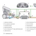
The method of induction heating of rolling bearings in a special apparatus is free from these disadvantages. The induction method heats up the bearings about 3 times faster than in an oil bath. The device is built into a fire-resistant asbestos-cement slab on which a heated bearing is placed.
A screw puller is used to remove the ball bearing from the shaft. The bearings are pulled together by the inner ring so that the pulling force is not transferred to the balls. When the bearing is pulled by the outer ring, the latter can burst due to wedging by the balls.
Since the moments of hinge friction of the ball relative to the two tracks are not equal, it can be assumed that this rotational movement will occur only with respect to the rolling trajectory at contact with which the moment of rotational friction is small. As a rule, the friction of contact with the inner contour is higher, this leads to the fact that the ball rotates without turning along the inner path and does not turn or turn outward.
If the bearing is running at high revs due to the action of centrifugal forces, the force of the ball at the contact of the two rings will be different, and as a result, the pressure angles will have different values. Under the influence of gyroscopic moments, there is a tendency to add additional ball spins, which, depending on the speed and lubrication conditions of the bearing, will not always be held back by frictional forces. This occurs in the case of skating with an adverse effect on the frictional moment in the bearing.
A worn bearing is replaced with a bearing of the same number. In exceptional cases, you can use a bearing, dimensions which can be installed in the socket by means of intermediate sleeves (in the outer and inner diameters) and thrust rings (in the width). The bearing is stuffed with thick grease for 2/3 of the chamber volume in order to avoid its squeezing into the engine.
For rigorous analysis, we must consider the vector angular velocity a ball, which usually has the following components in three directions. External forces acting on a bearing are associated with total axial and radial deformations. The theoretical analysis can be further deepened, taking into account the interaction between the balls and the cage, as a result of which the change in the amplitude of the orbital velocities of the balls around the mean value, i.e. the angular velocity of the cell is limited. The large amount of calculations justifies a full analysis only in special cases, for example, for ball bearings used in aerospace missions.
depends on the conditions of their operation, associated with increased friction in the shaft-bushing pair. The nature given view wear of rubbing surfaces is manifested in violation of their geometric dimensions and shape, the presence of scratches and scoring. In addition, in babbit-filled bearings delamination of the babbit layer and its crumbling is observed.
In particular, simpler situations such as symmetrically loaded radial bearings and the number of unknowns are significantly reduced. Since there is dry or mixed friction between the balls and the tread, it can be assumed that the gyroscopic moment is insufficient to rotate the ball in the loaded area of \u200b\u200bthe bearing. In addition, if the hypothesis of ball control is used, that is, the ball is considered to be rollable and pivotal relative to the rolling trajectory, which controls the movement and rolls and rotates with respect to another track, this will lead to a frictional force that opposes the gyroscopic moment will only act on contact with the lead by way.
Parts of bearing assemblies can be restored different ways, the choice of which depends on the design of the bearing unit:
■ grinding the shaft journal and replacing the sleeve with a new one or expanding (boring) the sleeve while increasing the shaft journal (one-piece sliding pins);
■ methods of plastic deformation followed by reaming the hole and fitting the sleeve along the shaft by scraping (one-piece plain bearings);
Thus, the analysis of the dynamics and kinematics of the ball is greatly simplified. Under dry friction conditions, the ball control hypothesis yields results that are reasonably accurate only for the ball's orbital velocities and for turning paths that are not really zero relative to either horse. The angles that are determined for a given load and bearing speed must also be determined by analyzing the position of the ball, which is greatly simplified for a symmetrical bearing load situation.
The control of the ball by the inner or outer ring is the result of analyzing the equation of moment in the direction perpendicular to the direction of motion of the orbit. Failure to comply with the conditions results in gripping control of the outer ring. When operating at low to medium speed, it is usually done so that the ball will be controlled by the inner ring. At high rpm, due to the action of centrifugal force, the force becomes higher and with limited speed control is captured by the outer ring.
■ scraping (split plain bearings);
■ casting with babbitt and scraping (split plain bearings).
Repair of bearing assemblies with one-piece plain bearings is carried out in different ways, depending on the nature and magnitude of their wear.
Restoration of bushings in case of wear along the inner diameter (in cases where it is impractical to replace bushings with new ones, for example, in large-size plain bearings) should be done as follows:
It should be noted once again that under the conditions of fluid friction, the hypothesis of ball control is no longer valid. For kinematic analysis bearing requires a comprehensive calculation. Differential slip. Due to the geometric shape of the rolling elements and elastic deformations, the contact surface will be a curve, its radius in the plane perpendicular to the direction of motion is equal to the average value of the harmonic rays of curvature in the corresponding plane. Because of this curve, the linear velocities of the points in the contact area will be different.
Only certain moments will reach the condition of equality of speeds, therefore, pure rolling. The rest of the points will be subjected to partially advanced and partially reverse slides. The magnitude of the differential sliding speeds can be determined by calculation. Considering the contact of the ball with the two rolling paths of the axial bearing, in which the outer ring is fixed, in order to analyze the relative motion, it will be associated with the stationary center of the ball. In dry or mixed friction mode, there will be virtually no differential sliding across the entire contact surface, frictional forces causing gripping that prevents relative sliding over a specific part.
■ clean the surface of the bushing hole;
■ reduce the inner diameter of the bearing bushing by upsetting or, by cutting out a longitudinal groove in the bushing, compress it and solder it using refractory solder;
■ unfold or re-bore the bushing to restore the fit.
In case of simultaneous wear of the sleeve and the shaft journal, both parts are restored. In this case, the sleeve is bored to a repair size and deployed, and the shaft is restored to a repair size by applying a repair allowance.
The adherence leads to tangential unitary forces in those areas that will contribute, as well as in the area of \u200b\u200bdifferential slip, to create rolling resistance torque, altering the pattern of wear. By choosing the geometry of the bearing, it is possible to change the position of the straight rolling lines so that the central contact point of contact, most desirable through conventional contact stresses, enters the engagement zone without differential sliding, resulting in reduced wear.
In order to study the frictional losses in bearings, first of all, aspects of rolling friction will be deepened. If there is weak lubrication on the contact surfaces, and dry or mixed friction occurs when the rotation speed decreases. The elementary frictional force will have the direction of the resulting relative sliding velocity, which usually has components in the directions of the two axes of the contact ellipse and a tangential component due to the rotational angular velocity. If you do not take into account the adhesion that takes place on a part of the contact surface, then in a first approximation the coefficient of friction will be the same in the contact area and will depend on the nature of the materials and the condition of the surfaces and their lubrication.
Restoration of bushings on the outer diameter is carried out in the same way as restoration of surfaces of the shaft journals.
a feature of which is the conical shape of the mating surface, is carried out by scraping the inner surface of the sleeve along the shaft journal. In this case, no additional processing is required. The clearance adjustment during assembly of the unit is carried out by axial movement of the sleeve relative to the shaft journal.
You can calculate the forces and moments of friction that occur in the equilibrium equations. Torque moment of elementary frictional forces about an axis passing through the center of the ball, perpendicular to the line defining the pressure angle. The calculation of bearing friction losses can be considered more easily if the rolling and pivoting movements are considered independent. In addition to the aforementioned factors, rolling friction also depends on the adhesion phenomenon on a specific part of the contact area.
In addition to the frictional loss due to the relative sliding of the contact surfaces, there are also losses due to elastic hysteresis during rolling. Elastohydrodynamic lubrication. Under certain conditions of speed and load, it is possible that in the contact zones between the body and the tread, a thickened film with sufficient thickness, apparently, causes friction of the fluid. In this case, in order to study the phenomena of the lubricating film, in addition to the hydrodynamic equations that establish the mechanism of carrier formation, elastic deformations of surfaces under the influence of film pressure will also be considered, whose contribution to determining the shape of the gap is decisive.
Repair of bearing assemblies with split plain bearings includes, first of all, restoration of the inner surface of the bearing shell, since during operation of bearing assemblies with split plain bearings, the inner surface of the shell is subjected to the most intense wear.
The restoration of the shells of a split plain bearing, depending on its design (monolithic or bimetallic), is carried out by scraping or pouring with babbitt followed by scraping. When restoring by scraping, the following operations must be performed:
■ install the complete bearing on a square, fixed in the lathe chuck so that the axis of its hole coincides with the axis of rotation of the spindle;
■ check the alignment with a dial gauge mounted on the shank and fixed in the tool holder:
put the measuring tip of the dial indicator into contact with the inner surface of the bearing shell so that the pointer of its reading device makes 2 - 3 turns;
turn the spindle of the machine, observing the deviations of the arrow of the reading device of the dial indicator; move the shelf of the square in the direction opposite to the deviation of the dial indicator hand; turn the spindle again, observing the deviations of the pointer of the dial gauge indicator and achieving the alignment of the bearing bore and the spindle rotation axis;
■ bore the inner surface of the insert to remove wear marks and restore the geometric shape;
■ remove the bearing from the machine and disassemble it;
■ Scrape the inner surfaces of the liners along the shaft journal, periodically checking the gap between the liners and the shaft journal. If, after restoring the bushings, it is not possible to provide the required clearance in the bearing due to shims between the housing and the bearing cap, then the shaft seating surfaces should be increased by applying a repair allowance.
To restore the inserts by pouring babbitt, the following operations must be performed:
■ clean and rinse the liners;
■ smelt the babbitt filling from the inserts using a blowtorch;
■ tinning the inner surfaces of the inserts with low-melting (soft) solder of the POS-ZO grade (thickness of the solder layer is 0.1 ... 0.2 mm);
■ coat the flat surfaces of the liner joints with refractory clay;
■ connect the upper and lower halves of the liners and fix their position with steel wire;
■ remove excess refractory clay squeezed out of the joint between the liners;
■ install the interconnected halves of the liner on a steel plate;
■ insert a casting core (steel or made of refractory molding material) into the opening of the insert so that the gap between it and the surface of the insert is uniform;
■ preheat the laboratory muffle furnace to the temperature corresponding to the babbitt pouring temperature;
■ put pieces of babbitt into a casting ladle;
■ place the casting ladle in a muffle furnace and hold it until the babbitt melts and the melt heats up to the pouring temperature (controlled by the furnace thermocouple);
■ pour babbitt into the gap between the rod and the insert;
■ disassemble the liner after it has cooled to ambient temperature;
■ install the insert into the body, cover with a lid and fasten;
■ install the slide bearing assembly on a square, fixed in the lathe chuck, and bore to ensure the correct geometric shape;
■ remove the bearing from the machine and disassemble;
■ Drill lubrication holes in the liner with a hand drill or drilling machine (benchtop or vertical);
■ fix alternately the lower and upper halves of the liner in a vice with the concave surface up;
■ cut through the lubrication grooves alternately in the lower and upper half of the insert;
■ Scrape the lower and upper halves of the liner along the seating journals of the shaft.
The restoration of parts of bearing assemblies with rolling bearings, regardless of the nature of the wear, begins with their disassembly, using special tools for this - pullers (Figure 2.4), which ensure disassembly of the assembly without damaging its parts.
After disassembling, the assembly parts must be thoroughly rinsed and inspected to identify defects. If damage is found on the surfaces of bearing parts, such as wear of raceways and rolling elements, crumbling of ring flanges, deformation of the cage, traces of corrosion on the working surfaces of the bearing or seats, they must be discarded and replaced with new bearings of the same standard size.
Only the seats on the shafts and in the housing, the sealing devices of the bearing assemblies (not in all cases) and the fastening parts of the bearings on the shaft and in the housing (also not in all cases) are subject to repair in the bearing units.
The seating surfaces of the shafts for rolling bearings and the surfaces intended for the installation of bearing fastening parts are restored by preliminary machining until the wear marks are removed, followed by applying a repair allowance and machining it in order to restore the fit dimensions.
The seating surfaces of the holes in the body parts are restored mainly by machining them to remove wear marks and restore the shape, followed by pressing the bushings and machining them (reaming or boring) to restore the fit dimensions.
Sealing devices are rebuilt in a variety of ways, depending on design, seal type and wear pattern.
Felt seals to protect bearing assemblies from impact environment, in case of contamination, washed in kerosene. With a high degree of wear of the felt seal as a result of its friction against the seating neck of the shaft, replace it with a new one, cutting it out of sheet felt using a punch of an appropriate size.
Labyrinth seals with chipped or dents in the walls of the annular grooves are restored by applying a repair allowance on their surface and boring the grooves to the nominal size.
Lip-type seals, which provide double protection of the bearing assembly from the environment and grease leakage, wear out mainly due to abrasion. The abrasion of the cuff occurs along the contact surface with the shaft journal. The degree of wear, and, consequently, the possibility of further exploitation of the cuff is determined using a probe inserted between it and the shaft journal. The 0.1 mm thick stylus should "bite" between the collar and the shaft. If it passes freely, it means that the cuff is worn out and needs to be replaced. For replacement, you can use standard ready-made cuffs, but you can make them yourself using special tools (Figure 2.5). If a rubber cuff is used in the assembly, then it is made of oil-resistant rubber by vulcanization in molds at a temperature of 140 ... 150 ° C.
Adjustment of the clearances in the bearing unit must be carried out in the event of a malfunction of the bearing units caused by a change in the clearances between the rolling elements and the raceways of the bearing rings. It is most difficult to perform such an operation of adjusting the clearances in the bearing supports of the spindles of metal-cutting machines with a rotational speed of up to 2,000 min-1.
Bearing arrangements of spindles, which have a large number of design solutions, must meet one basic requirement - to provide high accuracy of rotary movement, which is achieved by preloading in the bearing assembly. Due to the preload in the bearing unit, an optimal radial clearance is created between the rolling elements and the raceways of the rings, which determines normal work bearing assembly. To create a preload on the bearing in one way or another, a preload must be transferred, ensuring not only the elimination of gaps in the bearing, but also some elastic deformation of its working surfaces.

Figure: 2.6. Adjusting nut for roller bearing preload:
1 - ring; 2 - roller; 3 - outer ring of the bearing; 4 - inner ring of the bearing; 5 - nut; b - spindle
When installing double-row roller bearings in the bearing assemblies of the spindles, the preload is created due to the deformation of the inner ring when it is pressed onto seat, for which the appropriate fit is chosen. If the inner ring of such a bearing has a tapered bore, then it is mounted on the tapered spindle journal. In this case, the amount of interference is regulated by the axial movement of the bearing using the adjusting nut (Fig. 2.6).
When mounting the spindle in bearing units with paired angular contact bearings, preload can be created in different ways, which are shown schematically in fig. 2.7.
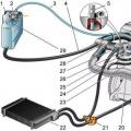
To determine the axial displacement of the bearing rings, assembled in units with a preload, a special device is used (Fig. 2.8). The device consists of a body (post 2), on which a pneumatic dynamometer 7 is mounted with a stop 6. The dynamometer is driven by a screw 9, connected to it by a coupling 10. The translational movement of the dynamometer without turning is provided by guide posts 8. A set of two bearings, in which it is necessary create a preload, set on the mandrel 22 located on the base plate 2. By rotating the screw, a force is created acting on the set through the ball 5 and the mandrel 4. The magnitude of the force is controlled by the pressure gauge 22.
After ensuring the action on the set of bearings of a given force, the axial displacement is measured:
where H1 and H are the distances between the outer and inner rings of the bearings, respectively, measured by end measures of length or an indicator bore gauge, mm.
In turn, the axial displacement АН determines the size of the support rings along the length and the amount of grinding of the inner ring (see Fig. 2.7, a).
Spacer sleeve 3 (see Fig. 2.8) is installed between the outer and inner rings of the bearings, depending on the orientation of the supports in the spindle unit and the specified axial compensation scheme.