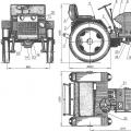
Shoe drum brakes:
and - mechanism with one-sided supports;
b - with spaced supports;
in - self-reinforcing mechanism;
r - mechanism with an expanding fist
Shoe drum brakes, despite their external similarity, differ significantly from each other in design and properties. The figure shows the main schemes of drum shoe brakes. Basically, they differ in the location of the pad supports and the nature of the driving forces that push the pads apart and press them against the drum from the inside. The difference in construction also predetermines the difference in properties.
Articulated swab and floating clog. Depending on the nature and type of shoe support, drum brakes and inner boots can be: with articulated shoes. In the case of a hinge shoe, its proximity to the drum is achieved by rotating around a fixed point. The floating shoe approaches the drum through a movement consisting of rotation and translation. Typical types of drum brakes and inner boots.
The simplex brake has a primary and secondary shoe that can be articulated or floated. FIG. 3a shows a simplex brake, in which both clamps 1 and 2 are pivotally secured in the bearings regardless of the direction of rotation. 10. One of the drums will push more on the reel.
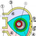
Drum mechanism with equal driving forces and one-sided arrangement of pad supports:
1 - brake drum;
2 - friction lining;
3 - block;
4 - brake shield;
5 - brake cylinder;
6 - returnable (tightening) springs;
7 - eccentric brake adjustment
Trailers and semi-trailers are equipped with proper drum brakes and internal couplings. The shoes are controlled by receiving cylinders. The braking system of the trailer also includes: compressed air reservoirs: half couplings for connecting to semi-trailers mounted on a tractor, a brake force regulator depending on the trailer load, connecting pipes. Depending on the number of connecting pipes between the trailer and the trailer, there are: - one pipe system; - Two-pipe system: - multi-wire.
Pipe drive system. If the trailer moves without braking, the compressed air supply to the trailer tanks is fed through a pipe. When the tractor is braking, by lowering the connecting line, the semi-trailer brake command is indicated. Two-pipe system. In this case, one of the pipes serves for the continuous supply of the compressed air trailer tanks. Braking control of the trailer is provided by compressed air from another pipeline, which is ventilated when the tractor is not braked. When the brake pedal is depressed, first there is a differential pressure in the trailer brake control line, which is intended to pre-brake the trailer.
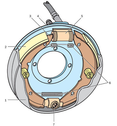
The illustration shows a drum brake with equal driving forces and one-sided shoe supports.
The platter is fixed to the bridge beam. In the lower part of the support disk, two pins are installed, on which eccentric washers are fixed. The position of the fingers is fixed with nuts. The eccentric washers are fitted with the lower ends of the pads. The adjusting eccentrics are fastened to the supporting disc by bolts, which are held against free rotation by pre-compressed springs. The compression spring presses each shoe against its adjusting eccentric. The spring fixes the adjusting eccentric in any position when it is turned by the head of the bolts. Thus, each pad is centered relative to the brake drum with adjusting eccentrics and eccentric washers of the fingers. The upper ends of the pads are in contact with the pistons of the working cylinder. The pads are held against lateral displacements by guide brackets with leaf springs.
The length of the friction pads attached to the front and rear pads is not the same. The front pad is longer than the rear. This is done to ensure even wear of the pads, since the front pad works longer as a primary pad and creates more braking torque than the rear pad. The brake drum is attached to the wheel hub. The drum is removable for easy access to the pads.
When braking, the fluid pressure in the wheel cylinder pushes the pistons in the opposite direction, they act on the upper ends of the pads, which overcome the spring force and are pressed against the drum. When the brake is released, the pressure in the cylinder decreases and thanks to the return spring, the pads are brought back to their original position.
The mechanism has a special drive lever connected by its upper end to one brake shoe, and through a bar - to the other. A parking cable is attached to the lower end of the arm. When pulling out the cable, the lever turns and presses against the drum first one block, and then another across the bar.
Brake car with spaced supports made according to the scheme (see fig. b). It has two identical brake pads, each mounted on a matching pivot pin. The pads are pulled together by springs. The ends of the pads are in contact with the pistons of the wheel cylinders. The working cylinders are connected to the master brake cylinder and to each other by a pipeline. The mechanism has automatic device clearance adjustment.
Platter servo brakes (see fig. c) mounted on the gearbox; it has two pads, expanding and adjusting mechanisms. The upper ends of the pads are pressed by the tension springs against the push rods of the release mechanism, and the lower ends are pressed against the supports of the adjustment mechanism. The force of the clamping springs of the left shoe is less than the force of the springs of the right shoe. The cracker of the adjusting mechanism can move with the pad supports by 3 mm relative to the screw. In the released position, the cracker is pressed against the body by strong springs and the specified gap is set from the side of the left block. When the brake lever is moved, the force from it is transmitted through the rod to the two-armed lever. The position of the brake lever in the braked state is fixed with a latch on the toothed sector. At the same time, the short shoulder of the two-armed lever presses on the expanding rod, which, sliding into the body, spreads the pushers of both pads with balls. The first to press against the drum is the left block, which has weaker clamping springs. If braking occurs when the car is moving forward, then this block is captured by the drum and its lower end moves the right block until it touches the drum (the block moves, which does not exceed 3 mm, counterclockwise). Both pads act as primary pads, with the drive force for the right pad being the frictional force transmitted from the left pad. Since the braking torque of the transmission parking brake increases main gear, then its dimensions are smaller than the dimensions of the wheel brakes or brakes installed after the cross-axle differential.
Equal displacement brake (see fig.d). The pads are supported on axles with eccentric necks. The axles are installed and secured with nuts in brackets riveted to the platter. When installing the brake, the axis is rotated and thereby the end of the shoe is displaced relative to the drum. The compression spring presses the pads against the expander. Two friction pads are riveted to the pads. The brake drum is cast from cast iron and attached to the wheel hub with studs. The expander is made in one piece with the shaft and is installed in the bracket. A lever is attached to the spline end of the shaft. A worm gear is placed in the lever, which serves to regulate the clearance in the brake mechanism.
When released, there is a gap between the shoes and the drum. When braking, the air pressure is perceived by the brake chamber membrane mounted on the bracket, and its rod turns the shaft with the expander fist behind the lever. The pads are pressed against the drum, causing the wheel to brake. The profile of the expander is made in such a way as to ensure that the ends of the shoes move at equal distances. This achieves a balanced braking mechanism, equal braking torques and pad wear.
Thus, the trailer is stretched, 12. Avoiding its breakage by pushing the tractor with the trailer. If the tractor vehicle has a double-circuit type, then its operating pressure is 6, 2-5 bar. Since the trailer braking system operates at 5.3 bar, the control valve must also reach the trailer pressure limit of 5.3 bar. In the case of a two-pipe brake system trailer, the tractor vehicle is equipped with a control valve that allows compressed air into one of the trailer hitch pipes during braking, which leads to its braking.
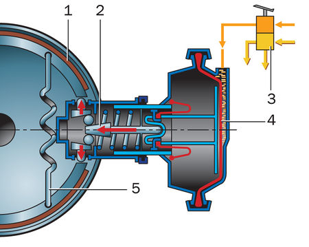
Braking mechanism with wedge-shaped expansion device and automatic clearance adjustment:
1 - block;
2 - expanding wedge;
3 - brake valve;
4 - brake chamber;
5 - spring
At the end of the braking process, whether due to operation of the service brake pedal or operation hand brake, the brake line of the trailer brake is broken and therefore deflected. At the same time, the control valve allows the trailer to be braked in advance so as not to damage the trailer. Tractor units are equipped with semi-purchases for connection with semi-trailers on trailers or semi-trailers. The drums are made of cast iron or molybdenum-alloyed simple ash, nickel and chromium, and sometimes a pressed steel plate, or a combination of a pressed steel disc and rim made of cast iron.
On a number of cars, brakes with a wedge expanding device and an automatic gap adjustment are used. A support is fixed on the support disk, into the cylindrical holes of which two pushers are inserted. Adjusting sleeves are located inside each pusher. On the outer surface of each adjusting sleeve, there is a spiral thread with a triangular profile of the teeth, and on the inner surface there is a thread into which the adjusting screw is screwed. During initial adjustment brake mechanisms by turning the adjusting screws, the gap between the brake drum and the shoes is set, the value of which is then automatically maintained. The ratchets are pressed against the adjusting sleeves, which have teeth that mesh with the outer teeth of the adjusting sleeves.
The expanding device consists of a wedge, two rollers (the axes of which are located in a separator), a thrust washer and a dust cap. When braking, a force is transmitted to the wedge from the brake chamber rod, as a result of which it moves in the axial direction and, by means of rollers, moves the pushers apart. The adjusting bushings and screws moving at the same time press the pads against the drum, and the ratchet pawl jumps over the teeth of the adjusting bushings. When release occurs and the tappets with their associated parts move in the opposite direction, the adjusting sleeves rotate due to the force generated in the engagement between the ratchet pawls and the sleeves, as a result of which the screws are turned out. The necessary clearances are established between the pads and the drum. As the clearance between the shoes and the drum increases, the ratchet pawls engage with another pair of teeth on the adjusting sleeve, which automatically restores the clearance in the brake mechanism.
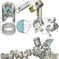
Currently, cars are molded in steel steel steel piles, which are then poured into a cast iron alloy ring. Plates are made by welding or forming a steel sheet, or cast from cast iron and less often from aluminum alloys. The surface of the boot is covered with a friction pad. Friction seals are usually made of a material similar to that used in clutch disc friction linings. The cylinders of central pumps and pumps for receiving hydraulic pumps are made of gray cast iron.
The play between the drums and the drum is checked and usually adjusted using eccentric cams that hold the shoe. Lift the vehicle off the ground using the jack, remove the wheel and, through the specially designed gauge viewport, measure the travel between shoe and drum. The game should not exceed 25mm from the factory, if the game is larger, the eccentric bolts are loosened making the necessary adjustments. Figure: 1. Setting the playing of swords and drum on hydraulic drive.
Brake drums for wheel and transmission brakes are usually cast in gray iron. In some brakes, the drum disc is stamped from sheet steel and connected to the cast iron drum when cast into a one-piece structure. Brake drums passenger cars made of aluminum alloy with a cast iron ring cast inside. Ribs are sometimes made on the drums to increase the rigidity of the structure and improve heat dissipation. Drum brake pads have a T-shape for cross-section rigidity. Sometimes the block rests loosely with its lower end on the platform and is not fixed. Such a block is self-aligning relative to the drum when braking.
Friction linings are made of materials with a high coefficient of friction (up to 0.4), high heat resistance and good wear resistance. Previously, hot pads were formed mainly from fibrous asbestos mixed with organic binders (resins, rubber, oils). Now the use of asbestos in brake linings is prohibited by law, since asbestos is recognized as a carcinogenic material.
Adjustment of travel between rolls and pneumatic drive drum. To regulate the playing between reels and reels, the deck vehicle is suspended. The adjustment is made by turning the shaft 7 relative to the lever shown in FIG. 2 so that the game between the reels and the reel is predetermined. The rotation of the shaft 7 is carried out by means of the screw 2, driven by a key. The blade 1 and the spring device fix the spindle shaft in the desired position. Figure: 2. Setting the play between swords and a pneumatic disc drum.
The drum brake mechanism is functionally designed to change speed mode vehicle. In addition, a drum brake mounted on the rear wheelset provides the parking brake function.
The main structural element brake mechanism of this type, in fact, which gave it such a name, is a drum, or a metal bowl, fixed on the wheel hub.
When adjusting, rotate the auger until the wheel brake that was previously rotated begins to rotate. Then loosen the screw until the wheel turns freely and checks the play between shoe and drum using a flat gauge. The play should be 4-6 mm to the end of the shoe near the exit and 2-6 mm at the axes of the shoe. To fully adjust the wheel brake mechanism, the clutches must be in a concentric position relative to the brake drum. This adjustment is carried out using the support pins.
After the adjustment, it is recommended to sample the brake system, especially considering that the braking effect is the same for the left and right wheels of the vehicle. Definition of the brake system. The brake performance test is carried out either by measuring braking distance vehicle for certain initial speeds, or by measuring the maximum deceleration to be achieved during braking. These tests shall be carried out horizontally, asphalted dry, with a full vehicle load.
The drum brake (Fig. 1) consists of the following main parts:
The brake drum, the material for the manufacture of which is high strength cast iron. The inner surface of the drum, which is in direct contact with the rest of the mechanism, is carefully polished. Mounted on support shaft (in this case, the bearing is pressed into the drum) or the wheel hub.
Check the brake linings for wear. For drum brakes, the thickness of the pad is measured through the viewing and adjustment windows, or in the absence of them, showing the drums. This adjustment is made after adjusting the service brake as follows: raise the rear of the car, release the parking brake, unscrew the nuts 1 and 2 of the hand brake, then tighten the nut 2 until the drums are in contact with the drum and the nuts are locked.
Defects in the braking system affect the braking process and can manifest themselves in various forms. The brake is not held loose or does not work. The defect is the result of a variety of causes associated with improper brake adjustment, damaged or worn parts, and fluid or air leaks in the case of hydraulic and pneumatic actuators. - Incorrect brake adjustment can mean: too high speed pedals, playing between drums and drum; loosening the adjusting nuts or springs for the automatic adjusting brakes, incorrectly clamping and adjusting the rolls to the pivot bolts.
Brake pads (item 4). They are made of metal and have a crescent shape. The working surface of the brake pad is equipped with a friction lining (based on asbestos).
Brake hydraulic cylinder (item 2). This is a hollow cast iron cylinder with two working pistons, filled with working (brake) fluid. The cylinder is equipped with a bleed valve to remove air from the brake system. To prevent leakage brake fluid use sealing cuffs.
Defect removal consists in adjusting freewheel pedals and when playing between drums and drum. - Friction seals are marked by the fact that when the pedal is depressed, the braking effect is reduced, since the friction between the drum and the seal seals is low. Removal of the defect consists in replacing the friction seals at the station maintenance... - The stuffing of the center pump piston seal and the piston piston piston causes the fluid, instead of being sent to the receiver cylinders or pushing their pistons when the brake pedal is pressed, escapes to the gaskets, so braking is not performed properly.
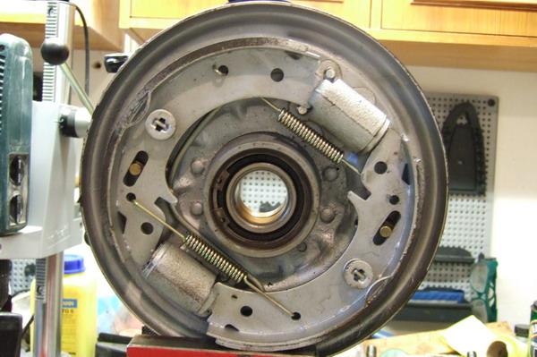
Upper (item 1) and lower (item 5) compression springs operating in "compression". Their main working function is to prevent divergence. brake pads in the "rest" mode.
Protective disc mounted directly on the hub (rear beam).
Spacer bar (item 3), which is a metal plate of a specific configuration (with special cutouts). Functional purpose of this element consists in the installation of a self-feed mechanism. Also, when installing braking device on the rear wheelset, the spacer bar actuates the second brake pad while allowing the parking brake to function. It is used in drum brakes with one brake cylinder.
Rehabilitation is carried out at a service station by removing the receiving cylinders or central pump, cleaning irregularities, replacing gaskets, flushing the unit, and introducing new fluid. - Air or vapors in the piping, as well as system leakage, are caused by lack of fluid in the installation, excessive use of brakes, so that due to heating, ethyl or methyl alcohol evaporates and plugs, cracks or damage to fittings, cylindrical or metal fittings are formed.
Some faults can be removed by filling the fluid and breathing out the air or vapor in the pipes. 18. Have pipes or cracked or damaged connections replaced by a workshop. - Air leakage from the air brake is the same malfunction for fluid loss in the hydraulic actuator. Air loss can be seen either through the noise generated at the air outlet or through the air pressure gauge. These losses occur at joints, metal pipes, air tank.
Self-drive mechanism (in the form of two eccentrics located in the protective disc housing), which ensures the expansion of brake pads with worn friction linings.
Drum brakes - how they work

The principle of operation of a drum brake is as follows:
The brake will rinse even if the brake pedal is not actuated. Some errors can be partially removed along the route. If the spring for shoe repair is damaged or weakened, stop the brake on the wheel by connecting the boots to the cable to avoid touching the drum. A new spring has been installed at the service station. During braking, the vehicle pulls it to one side. Inconveniences are usually associated with brake malfunction and brake system failures such as eccentric drums, inadequate shims, spindles to overcome excessive plugging, clogging, warping or cracking of the flexible coupling, lubricant penetration into friction guns, diaphragm breakage or seal damage wheel brake cylinder, tire pressure is different.
When the driver presses the brake pedal, pressure builds up in the brake circuit.
Under the influence of the brake fluid pressure the pistons brake cylinders, overcoming the resistance of the clamping springs, initiate the divergence of the brake pads.
Brake pads, diverging and tightly fitting friction linings to the working surfaces of the brake drums, reduce their rotation speed, thereby slowing down the rotation of the vehicle wheels.
A malfunction can occur on one or all wheels while driving or after braking even after the driver has released the brake pedal. Reasons for wheel blocking: pinching or seizure of the cylinder piston of one or more wheels, ovalization of the drums, 19.
Hammering the flex connector, damaging or loosening the shoe spring. Defects are removed at a service station. The malfunction is due the following reasons: Poor fixation of shoe friction lining, destruction of blocks, joints of rotation or ovalization of drums, presence of large games in the bearings of wheels or planetary shafts, excessive clearance of the suspension spring, deflection of percussion shafts or deformation of drums, friction pads are dull, too long or too harsh. All faults are removed at a service station.
The braking efficiency of drum-type brakes is slightly lower than the same indicator disc brakes... Thus, the difference in stopping distance can differ significantly (up to 20%). And there are several, quite objective reasons for this: