The car has a classic layout with a front engine parallel to the longitudinal axis of the car and rear driving wheels. With this arrangement, the torque from the engine to the drive wheels is transmitted through the following transmission units: clutch, gearbox, cardan gear and mechanisms rear axle (main gear, differential, axle shafts).
The clutch is the link between the engine and the transmission. It provides reliable transmission of torque from the engine to the drive wheels, temporarily disconnects the engine and transmission when shifting gears and braking, and smoothly connects them when starting off the vehicle, and also protects transmission parts from dynamic loads.
On VAZ cars, two types of clutches are used: 2103 and 2121. The first type of clutch is used on cars equipped with engines with a displacement of 1.2; 1.3; 1.5, the second type - on cars with engines with a working volume of 1.6 liters. To distinguish the leading parts of the clutch (clutch cover assembly with a pressure plate and a spring), a mark is made on the type 2121 clutch in the form of a hole 6 mm in diameter, in one of the slots of the pressure spring petal. The driven discs also differ, both in shape and in the width of the friction linings. For clutch type 2103, the width of friction linings is 29 mm, for clutch 2121 - 35 mm, and they are riveted with a large number of rivets.
On VAZ-2105 and 2107 cars, a clutch with a release fork is installed, in which the retaining spring has a circular cross-section, instead of the flat one used on other models. Both types of plugs are interchangeable.
The clutch is single-disc, dry, permanently closed (always on), with a central pressure spring and a torsional vibration damper on the driven disc. A number of clutch parts have a permanent, rigid connection to the flywheel, so when the engine is running, these parts rotate with crankshaft with the clutch engaged and disengaged. These parts make up the driving part of the clutch. Other parts are rigidly connected to the gearbox drive shaft -16-. They receive torque from the flywheel and the clutch drive by frictional forces and enter the driven clutch. Shutdown, i.e. the separation of the driving and driven parts of the clutch is carried out through a hydraulic drive. The driving and driven parts of the clutch are located together with the flywheel in an aluminum housing -13-. At the front, the cavity of the clutch housing is closed by a stamped steel cover -12-. A gearbox is attached to the rear end of the crankcase.
The leading part of the clutch is a non-separable unit, which has a casing -14-, a pressure plate -10-, a central pressure spring -1- and a number of other minor parts. This assembly is secured to the flywheel by six bolts with spring washers. Accuracy of the flywheel and clutch housing is achieved with three locating pins.
Figure: 14. Clutch VAZ-2107.
1. Pressure spring;
2. Friction linings of the driven disc;
3. Rivet of the pressure spring;
4. Driven disk;
5. Rivet-stop damper (torsional vibration damper);
6. Front damper plate;
7. Rear damper plate;
8. The hub of the driven disk;
9. Damper spring;
10. Pressure disk;
11. Flywheel;
12. Cover of the clutch housing;
13. Clutch housing;
14. Clutch cover;
15. Front cover of the transmission;
16. Drive shaft of the gearbox;
17. Clutch release bearing clutch;
18. Friction ring of thrust flange;
19. Spherical bearing clutch release forks;
20. Spring of the clutch release fork;
21. Ring of the bait spring;
22. Clutch release fork pusher;
23. Clutch release fork;
24. Clutch slave cylinder;
25. Retractable spring of the clutch release fork;
26. Damper friction rings;
27. Support ring of the spring washer;
28. Damper spring washer;
29. Plate connecting the pressure plate to the clutch cover;
30. Clamp of the pressure spring;
31. Coupling plate of thrust flange and clutch cover;
32. Thrust flange of the pressure spring;
33. Clutch release bearing;
34. Connecting spring of the fork and clutch release;
I. Damper action diagram.
The clutch cover -14- is stamped from steel. On the outer flange of the casing, holes are made for bolts and pins for attaching the casing to the flywheel, and on the inner flange there are holes for rivets -3-, which connect the clutch casing to the pressure spring. A pressure plate -10- and a central pressure spring -1- are fixed in the cavity of the clutch cover.
Pressure plate -10- made of cast iron. There are twelve ventilation slots on the annular ledge of the disc, in three of them the clips -30- are riveted. The pressure plate is connected to the casing -14- by three pairs of steel plates -29-, which are riveted to the casing at one end and to the pressure plate at the other. This elastic connection ensures the transmission of torque from the clutch cover to the pressure plate, as well as axial movement pressure plate in the casing when engaging and disengaging the clutch.
The pressure spring -1- is stamped from sheet spring steel, has the shape of a truncated cone. It is located between the cover -14- and the pressure plate -10-. Acting with its outer edge on the protrusions of the pressure plate, the spring -1- presses the driven plate -4- through the disk -10- to the surface of the flywheel with a force that prevents it from slipping. Supports for the pressure spring, relative to which its deflection occurs when the clutch is released, are two O-rings -21-; one ring is located between the clutch cover and the pressure spring, the other between the spring and the heads of nine step rivets. With its outer edge, the pressure spring enters the grooves of the three retainers -20- and, when the clutch is released, through them moves the pressure plate away from the driven disc. The inner part of the compression spring has radial slots that end with oval holes. These slots form petals on the surface of the spring that act as clutch release levers. Due to the elasticity of the plates -31-, the thrust flange -32- is pressed against the petals of the pressure spring, to the outer surface of which the friction ring -18- is glued.
The drive part of the clutch assembly undergoes static balancing and its unbalance should not exceed 250 g * mm. This imbalance is achieved by drilling out the metal in the lugs of the pressure plate. The driven part of the clutch consists of a driven disc -4- assembled with linings -2- and a torsional vibration damper (damper).
The driven disc is steel, has radial slots that divide it into twelve sectors, alternately bent in different directions, which creates a wavy shape of the working surface of the driven disc. Friction linings -2- are riveted to the sectors of the driven disk, independently of one another, with copper or aluminum rivets. The rivet heads are buried in the holes of the linings, and their rods are riveted from the side of the driven disk. For this, holes are made in the opposite friction lining. This attachment of the friction pads maintains the wavy surface of the driven disc, which ensures smooth engagement of the clutch, as the driven disc becomes flat gradually as the pressure on its surface increases. In this case, the initially driven disc slides relative to the surfaces of the flywheel and pressure disc, and the transmitted torque increases gradually. This protects the transmission components from overloading and ensures a smooth start-off.
The driven disc -4- is connected to the hub -8- with a torsional vibration damper, which provides an elastic connection between them. The presence of a torsional vibration damper is explained as follows. With a sharp change in the speed of the car, when hitting the unevenness of the road, with a sharp engagement of the clutch and due to the uneven operation of the engine, dynamic loads appear in the car's transmission, causing the transmission shafts to twist (unwind). Uneven engine torque can cause significant overloads in the transmission due to the occurrence of torsional vibrations and resonance when the frequencies of the transmitting loads coincide with the frequencies of the natural vibrations of the transmission. Elastic vibrations of the transmission lead to noise in mechanisms and units, to dangerous vibrations, and sometimes to breakdowns of parts when the amplitudes reach large values. The energy of torsional vibrations is absorbed by a damper (damper). It consists of front - 6- and rear -7- plates, two friction rings -26-, support ring -27-, spring washer -28- and springs -9-. Through these parts, the hub -8- is connected to the driven disc -4-.
The hub -8- of the driven disc is located on the splines of the drive shaft -16- of the gearbox. The hub flange has six rectangular windows and three horseshoe-shaped cutouts. Thrust pins 5 of the torsional vibration damper pass through these notches, which connect the front plate -6-, the rear plate -7- and the driven disc -4-.
In the damper plates and in the driven disc, as well as in the hub, rectangular windows are made in which the springs -9- are located. The springs are kept from falling out of the windows by flanging on both damper plates. The elasticity of the springs of the torsional vibration damper is different, the harder ones are painted with light paint. They are installed between less elastic springs. This ensures smoother operation of the elastic damper element and expands its area of \u200b\u200baction. Friction rings -26- are fitted on both sides of the hub flange. The spring washer -28- of the damper through the support ring -27- creates a constant frictional moment between the surfaces of the friction rings and the hub.
The damping of torsional vibrations occurs due to friction forces that arise when the disc -4- and plates -6- and -7- move relative to the hub -8- and due to the elasticity of the springs -9-. The action of the elastic element of the torsional vibration damper is limited by three thrust pins -5-, which abut against the horseshoe-shaped notches of the hub.
When assembling the clutch, the driven disc is only installed in one position, so that the protruding part of the hub -8-, on which the groove is made, faces the gearbox. The axial runout of the driven disc must not exceed 0.5 mm, otherwise the clutch will not completely disengage.
The clutch is disengaged via a hydraulic drive, the force from which is transmitted through the fork -23- and the clutch -17- to the clutch release bearing -33-. This bearing is not lubricated during vehicle operation. Lubrication is laid in it during its manufacture.
The clutch -17- complete with radial bearing -33- is located on the guide bush of the front gearbox cover -15-. The clutch release fork is pressed against the clutch lugs by the spring -34-. It rests on a ball joint -19-, the spherical head of which fits into the socket of the plug. On a ball joint, the fork is held in place by a spring -20- which is mounted in the fork. A pusher -22- passes through the hole in the outer end of the fork -23-, onto the threaded end of which the adjusting nut -49- is screwed (see Fig. 15). This nut is secured with a lock nut -50-. The fork is pressed against the spherical surface of the adjusting nut by a spring -25- (see Fig. 14). By changing the working length of the pusher -22-, the clearance between the clutch release bearing -33- and the thrust flange ring -32- is adjusted. It should be equal to 2 mm, which corresponds to the free travel of the pusher of the working cylinder 4-5 mm.
The hatch of the clutch housing -13-, through which the end of the fork -23- passes, is closed with a rubber boot.
CLUTCH RELEASE ACTUATOR
The clutch is released hydraulically, the design of which ensures smooth engagement of the clutch and reduces labor intensity to a minimum maintenance clutch. The drive includes elements that reduce the effort on the pedals when the clutch is disengaged. Refueling drive brake fluid "Neva" or "Dew". Drive capacity 0.2 l.
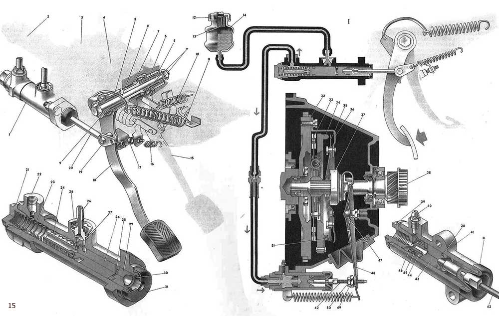
Figure: 15. Clutch drive.
1. The main cylinder of the clutch release drive;
2. The main cylinder of the brake drive;
3. Vacuum amplifier;
4. Bracket for attaching the clutch and brake pedals;
5. Internal bushings for clutch and brake pedals;
6. Servo spring hook;
7. Spacer sleeve;
8. The axis of the pedals;
9. Outer bushings for clutch and brake pedals;
10. Retractable spring of the brake pedal;
11. Servo spring;
12. Tank cap;
13. Cork reflector;
14. Master cylinder reservoir;
15. Brake pedal;
16. Clutch pedal release spring;
17. Limiting screw of the clutch pedal;
18. Clutch pedal;
19. Plate of the retracting spring of the clutch pedal;
20. Pusher;
21. Plug of the main cylinder body;
22. Main cylinder body;
23. Piston spring;
24. Piston of the master cylinder;
25. Lock washer;
26. Fitting;
27. Fitting gasket;
28. Sealant;
29. Pusher piston;
30. Retaining ring;
31. Protective cap;
32. Flywheel;
33. Driven disk;
34. Pressure disk;
35. Pressure spring;
36. Clutch cover;
37. Clutch release bearing;
38. The drive shaft of the gearbox;
39. Plug of the working cylinder body;
40. Fitting;
41. The body of the working cylinder;
42. Clutch release fork pusher;
43. Piston;
44. Support plate of the piston spring;
45. Spring;
46. \u200b\u200bSpring support washer;
47. Ball bearing of the clutch release fork;
48. Clutch release fork;
49. Adjusting nut;
50. Locknut;
51. Clamp of the pressure spring;
I. Scheme of the clutch hydraulic drive.
The clutch and brake pedals are suspended from the bracket -4- with the bolt -8-, which is the axle for both pedals. On the axle there are two inner metal bushings -5- and a spacer plastic bushing -7-, and on the pedal hubs there are two split outer bushings 9 made of plastic. These bushings are not lubricated during vehicle operation.
The clutch pedal -18- is pivotally connected with a finger to the pushrod -20- and the clutch pedal release spring plate -19-. The hemispherical end of the pusher is in contact with the piston -29- of the master cylinder. Hook -6- is inserted into the cutout of the clutch pedal bracket, the other end of which is connected to the servo-spring -11-. This spring reduces the force on the pedals -18- when disengaging the clutch. When the pedal is depressed, the pedal bracket together with the hook is lifted, thereby forming a shoulder between the centerline of the servo spring and the center of the pedal axis. A moment is created that pulls the upper part of the clutch pedal, thereby reducing the force applied to the lower part of the pedal when the clutch is disengaged. In the initial position, the clutch pedal is pressed by the spring -16- against the stop screw -17- with a rubber buffer.
The bracket -4- for the clutch and brake pedals is attached to the bulkhead. Attached to the bracket plate master cylinder -1- clutch release drive and vacuum booster -3- assembled with main brake cylinder -2- brake drive.
Spring -23- and pistons -24- and -29- are installed in the cavity of the housing -22- of the master cylinder of the clutch release drive. A seal -28- is located between the pistons. The presence of two pistons in the cylinder reduces the radial loads on the piston -24- of the master cylinder when the pusher -20- acts on the piston -29- and improves the sealing of the pistons in the cylinder by compressing the seal between the pistons -24- and -29-.
In the groove of the piston -24- there is an O-ring, which ensures tightness in the working cavity of the cylinder. An axial channel and a radial bypass hole in the piston communicate the working cavity of the cylinder with the groove of the seal ring. Therefore, when pressure is created in the working cavity of the cylinder, it expands the sealing ring radially and improves the sealing of the piston in the cylinder. At the same time, the sealing ring plays the role of a valve through which the working cavity of the cylinder communicates with the reservoir of the clutch hydraulic drive when the pedal is released. The O-ring does not cover the expansion hole. Pistons -24- and -29- return to their original position under the action of spring -23-, which rests on one end against plug -21- with the other against piston flange -24-. All parts in the master cylinder are held in place by a retaining ring -30-. The protective cap -31- protects the cylinder cavity from dirt.
In the tides of the cylinder body, a pipeline is fixed, which diverts fluid from the master cylinder to the working cylinder, and a fitting -26-, connected by a hose to the reservoir of the clutch hydraulic drive. The nipple -26- in the bore is sealed with a rubber gasket -27- and secured with a lock washer -25-.
The slave cylinder is attached to the clutch housing with two bolts. The piston -43- with two sealing rings -28- is installed in the cylinder body -41-. One of them is installed in the piston groove, and the other is constantly pressed by the spring -45- through the support plate -44- to the end surface of the piston groove. The spring -45- is held on the piston by a support washer -46- and a circlip. Through axial drilling and a radial hole in the piston, the working cavity of the cylinder communicates with the groove of the sealing ring, which ensures a tighter fit of the ring to the cylinder mirror with increasing fluid pressure in the working cavity.
The pusher -42- of the clutch release fork rests against the piston seat -43-. A nipple -40- for bleeding the clutch drive and a plug -39- are screwed into the cylinder body, into the threaded hole of which the hose tip is screwed.
The reservoir -14- of the clutch release hydraulic drive is secured with a clamp on the bracket of the bulkhead. The reservoir is made of translucent plastic, which makes it easier to check the fluid level in the actuator. A plug -12- with a corrugated rubber baffle -13- is screwed onto the neck of the tank, which protects the tank cavity from contamination, and also prevents vacuum in the tank when the liquid level drops and acts as a damper. The flange part of the reflector is clamped between the plug and the reservoir, thereby sealing the reservoir.
Clutch work. The principle of operation of the clutch is based on the transmission of torque from the flywheel and the clutch drive part to the driven disc, and therefore to the transmission drive shaft -38-, due to the frictional forces that arise between the discs when the clutch is engaged. In this position, due to the elasticity of the pressure spring -35-, the pressure plate -34- clamps the clutch plate -33- between itself and the flywheel with a force that prevents it from slipping. Therefore, when the engine is running, the drive and driven parts of the clutch will rotate together, transmitting torque from the engine crankshaft to the drive shaft -38- of the gearbox.
When the clutch is disengaged, the force from the pedal through the pusher -20- is transmitted to the pistons -29- and -24-, which, overcoming the resistance of the spring -23-, move in the master cylinder. In this case, the front O-ring closes the expansion hole of the cylinder, and its cavity is disconnected from the reservoir. The liquid enters the cavity of the working cylinder through the pipe and hose, moving the piston -43- and the pusher -42-. The force from the pusher is transmitted through the adjusting nut -49- to the clutch release fork -48-. Turning relative to the ball joint -47-, the fork moves the bearing sleeve -37- for releasing the clutch. Initially, the clearance between the bearing and the thrust flange friction ring is selected. This ends the pedal free travel.
During the working stroke of the clutch pedal, the thrust flange, acting on the petals of the pressure spring, bends it on the support rings. The outer edge of the spring drives the pressure plate -34- away from the driven plate through the clips -51-, and the transmission of torque to the gearbox is interrupted.
When the clutch pedal is released, all parts of the master and slave cylinders, as well as the clutch pedal, return to their original position under the action of the springs. The front o-ring of the master cylinder piston moves away from the compensation hole and the cavities of the master cylinder and the reservoir communicate. The pressure in the system drops and the pressure plate -34- is pressed against the flywheel surface by the pressure spring -35-. When pressed down on the clutch disc, its wavy surface gradually becomes flat, allowing the disc to slip first, thereby engaging the clutch smoothly. In this case, the torque from the flywheel -32- is transmitted to the casing -36- and the pressure plate and, due to frictional forces, to the driven disc -33-, then from it through the damper elements to the hub of the driven disc and through the splined connection to the drive shaft of the gearbox ...
The energy of torsional vibrations of the engine crankshaft is absorbed by the friction forces of the damper friction element and the elasticity of its six springs. When the torque changes, the driven disc -4- (see Fig. 14) together with the damper plates -6- and -7- move relative to the hub -8-. In this case, friction occurs between the surface of the hub and the friction rings -26- of the damper, the springs -9- are compressed, transmitting torque to the hub. The compression travel of the springs depends on the amount of torque transmitted. Different spring rates provide a softer clutch engagement. The rotation of the driven disc together with the damper plates relative to the hub is limited by the stop of the pins -5- in the horseshoe-shaped notches of the hub. This stops the compression of the springs -9-.
When the clutch pedal is released abruptly, the liquid does not have time to fill the volume released by the piston -24- (see Fig. 15), and a vacuum is created in the working cavity of the master cylinder. Under its action, the liquid through the cylinder bore, the gap between the rear end of the sealing ring and the piston groove -24- flows through the radial bore in the piston into the working cavity of the cylinder, which ensures the subsequent effective action of the clutch release drive.
In order for the clutch to completely disengage, it is necessary to provide a clearance of 0.1-0.5 mm between the pusher -20- and the piston -29- when the clutch pedal is released. This gap is set with the limit screw -17- and is determined by the free travel of the pedal equal to 0.4-2 mm.
In order for the clutch to fully engage, a gap is required between the clutch release bearing and the thrust flange friction pad. Normal clearance corresponds to the free travel of the pusher -42- of the clutch release fork, equal to 4-5 mm. It is adjusted with nut -49-. After making these adjustments, the clutch pedal free travel is 25-35 mm.
In addition to the specified clearances, clutch pedal use and serviceability affect the durability and reliability of the clutch. hydraulic drive... Disengage the clutch vigorously, i.e. depress the clutch pedal quickly, but smoothly, without jerking, in order to ensure quick disconnection of the discs and prevent them from slipping. When engaging the clutch, do not allow a sharp clamping of the driven disc between the surfaces of the flywheel and pressure plate. Otherwise, the discs may be damaged, and above all the slave. Therefore, the clutch pedal must be released smoothly and without delay in some intermediate position.
If the clutch release drive is leaking or air enters it, the clutch is partially released. In the first case, due to fluid leakage and pressure drop in the actuator, in the second, due to air congestion in pipelines that prevent the passage of fluid into the working cylinder. The main criteria for the serviceability of the clutch release drive are the above clearances and the tightness of the drive.
During the operation of the vehicle, due to wear of the clutch discs and, above all, the driven one, the gap between the friction lining of the thrust flange and the bearing -37- of the clutch release is gradually selected, which leads to a decrease freewheel clutch pedals.
..TRANSMISSION VAZ-2107 (FOUR-STAGE)
While the vehicle is in motion, the torque on its drive wheels must be periodically changed to ensure optimal speed and cross-country ability of the car, as well as the most economical mode of engine operation. So, for example, when the car is moving from a standstill, uphill and on soft soils, the torque on the driving wheels should be greater than when driving on horizontal sections of the road with a hard surface and good grip wheels of a car with a roadbed. The amount of torque is changed by the gearbox. It also allows the vehicle to move in reverse and decouple the engine from the transmission when the vehicle is stopped or parked and when the vehicle is coasting with the engine running.
Most of the cars are equipped with four-speed gearboxes, some cars are equipped with a five-speed one.
The four-speed gearbox has the following data - gear ratios: first gear - 3.67; second gear - 2.10; third gear - 1.36; fourth gear - 1.00; reverse - 3.53. Transmission oil TAD-17i is poured into the gearbox, its capacity is 1.35 liters.
Due to the small number of gears, the gearbox is compact and its design is quite simple. It provides intensive acceleration, high average vehicle speed and economical engine operation. Constant meshing helical gears and synchronizers in all gears forward motion ensure quiet operation of the transmission and its durability.
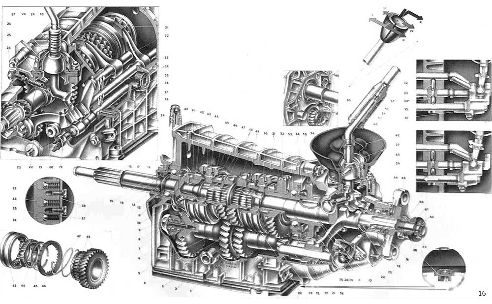
Figure: 16. Transmission (four-speed).
1. Bottom cover;
2. Plug for filler and control holes;
3. Gear wheel of the second transfer intermediate shaft;
4. Gear wheel of the third transfer of the intermediate shaft;
5. Intermediate shaft;
6. Front bearing of the intermediate shaft;
7. Bolt of the clamping washer;
8. The clamping washer of the front bearing of the intermediate shaft;
9. Gear wheel of constant engagement of the intermediate shaft;
10. Gear wheel of constant engagement of the drive shaft;
11. Spring washer;
12. Retaining ring;
13. Rear bearing of the drive shaft;
14. Drive shaft oil seal;
15. The front cover of the gearbox with the guide sleeve of the clutch release bearing;
16. Bearing locating ring;
17. Clutch housing;
18. Drive shaft of the gearbox;
19. Reversing light switch;
20. Gear wheel of reverse gear of intermediate shaft;
21. Intermediate reverse gear;
22. Reverse gear fork;
23. Retractable spring of the gear lever;
24. Retaining spring bolt;
25. The guide cup of the gear lever;
26. Lever ball joint;
27. Spherical washer;
28. Spring;
29. Gear shift lever;
30. Fork of inclusion of I and II transfers;
31. Fork of inclusion of III and IV transfers;
32. Stem of the fork for engaging 1st and 2nd gears;
33. Rod of a fork of inclusion of III and IV transfers;
34. Blocking rusks;
35. Stem of the reverse gear inclusion fork;
36. Ball stem lock;
37. Retainer spring;
38. Latch cover;
39. Breather;
40. Needle bearing of the front end of the driven shaft;
41. Thrust washer of the synchronizer spring;
42. Gear ring of the IV gear synchronizer;
43. Sliding clutch for synchronizer of III and IV gears;
44. The hub of the sliding clutch of the synchronizer of III and IV gears;
45. Retaining ring of the synchronizer;
46. \u200b\u200bBlocking ring of the synchronizer;
47. Synchronizer spring;
48. Gear wheel and ring gear of the synchronizer III gear;
49. Gear wheel and ring gear of the 2nd gear synchronizer;
50. Driven shaft;
51. Gear wheel and ring gear of the 1st gear synchronizer;
52. Bushing of gear wheel of 1st transfer;
53. Intermediate bearing of the driven shaft;
54. Intermediate bearing retaining plate;
55. Gear wheel of reverse gear of the driven shaft;
56. Retaining ring of the intermediate shaft reverse gear;
57. Elastic cushion damper gear lever;
58. Damper rubber bushing;
59. Damper spacer sleeve;
60. Damper locking sleeve;
61. Spacer rod sleeve;
62. Inner cover of the gear lever;
63. Lever guide pin;
64. Oil seal of the driven shaft bearing;
65. Flange elastic coupling cardan shaft;
66. Nut;
67. Centering ring seal;
68. Centering ring;
69. Retaining ring of the centering ring;
70. Rear bearing of the driven shaft;
71. Drain plug;
72. Dirt reflector;
73. The leading gear wheel of the speedometer drive;
74. Speedometer drive;
75. Rear cover of the transmission;
76. The axis of the intermediate reverse gear;
77. Rear bearing of the intermediate shaft;
78. Gear wheel I transfer of the intermediate shaft;
79. Gearbox housing;
80. Sliding clutch for synchronizer of 1st and 2nd gears.
The gearbox consists of three shafts: a driving shaft -18-, an intermediate -5- and a driven shaft -50- with gears and synchronizers, an axle -76- with an intermediate gear -21- reverse and a mechanical drive for shifting. The shafts and gears of the gearbox are housed in a cast aluminum housing -79, and the gearshift drive parts are located in the rear cover -75-.
Centering of the gearbox with respect to the clutch housing is achieved by precisely fitting the front cover -15- of the gearbox into the bore of the clutch housing -17- and installing the front bearing in the socket of the end of the engine crankshaft.
To prevent the transmission of oil from the gearbox to the clutch discs, the front cover -15- has an opening for oil from the gearbox housing to the clutch housing.
The crankcase -79- is fastened to the clutch housing -17- with the front plane. At the front, the gearbox housing is closed with a cover -15-, in which the oil seal -14- of the drive shaft is installed, at the rear - with a cast cover -75- made of aluminum alloy, and at the bottom with a stamped cover -1-. This cover has a hole closed with plug -71-. The gearbox cavity is communicated with the atmosphere through the breather -39-, which excludes pressure in the crankcase and oil leakage through the seals. Oil is poured through a hole closed with a plug -2-. The oil level should be up to the lower edge of the filler hole.
The drive shaft -18- rotates in two ball bearings, one of which is located at the end of the engine crankshaft, and the other in the front wall of the gearbox housing. The rear bearing -13- is held on the shaft by a circlip -12- and a spring washer -11- between the inner bearing race and the circlip. In the groove in the outer ring of the bearing -13- there is a locating ring -16-, which is clamped between the front wall of the box and the clutch housing. A spring washer -11- is installed between the front cover -15- and the outer bearing race -13-. Such a fixation rear bearing keeps the shaft from axial movement.
On the front of the drive shaft, splines are cut with which it connects to the clutch disc. Together with the shaft -18- helical gear -10- is made, which is in constant mesh with the gear -9- of the intermediate shaft. Spur gear -42- of the fourth gear synchronizer is brazed with copper to the drive shaft -18-. The clutch -43- is connected to this crown when the 4th gear is engaged.
The intermediate shaft -5- is a block of four gears, which is supported by the front end on the double-row ball bearing -6-, and the rear end on the roller bearing -77-. The front bearing is fixed to the shaft with a bolt -7- with spring and flat washers -8-. The rear bearing is held on the shaft together with the reverse drive gear -20- by a circlip -56-. The shaft is held against axial displacement by a front bearing locating ring, which is clamped between the gearbox and clutch housings.
The driven shaft -50- rotates in three bearings. The front needle bearing -40- is located in the drive shaft seat. To lubricate the needle bearing, holes are drilled in the drive shaft gear through which oil from the crankcase is sprayed into the bearing.
The intermediate bearing -53- is located in the rear wall of the gearbox housing. It is fixed in the socket by a locking plate -54-, which is attached to the rear wall of the crankcase with screws. The intermediate bearing locating ring is clamped between the plate and the crankcase. On the shaft, the bearing is clamped between the bushing -52- and the reverse gear -55-, which is held on the shaft by a circlip -12- with a spring washer -11-.
The rear bearing -70- of the driven shaft is located in the rear cover. On the driven shaft, the bearing is clamped with a nut -66- between the drive gear -73- of the speedometer drive and the flange -65- of the elastic coupling. The rear end is sealed with a gland -64-, the working edge of which compresses the cylindrical part of the flange -65-. The stuffing box is protected from contamination and mechanical damage dirt reflector -72-.
On the heat-treated journals of the driven shaft, gears -48- and -49- of the third and second gears rotate. The gear wheel -51- of the first gear rotates on a heat-treated steel sleeve -52-, which is put on the shaft. Each of these gears has two rims. The helical rims are in constant mesh with the gears of the intermediate shaft -5-, and the spur rims are connected when the gears are switched on with the couplings -43- and -80- of the synchronizers and through them and the hubs of the synchronizers transmit the torque to the driven shaft.
For better lubrication heat-treated shaft journals and landing holes of gears of III and II gears; small longitudinal grooves are cut on the driven shaft. Oil is supplied to these surfaces through radial holes drilled in the grooves between gear rims -48- and -49-. In a similar way, oil is supplied to the rubbing surfaces of the sleeve -52- and the gear -51-.
On the two belts of the driven shaft, three deep grooves are cut into which the protrusions of the hubs of the sliding synchronizer couplings enter, which ensures their rigid connection with the shaft. The hub -44- of the synchronizer clutch for III and IV gears with its inner end part abuts against the shoulder of the driven shaft and is pressed against it with a disk spring washer, which is fixed on the shaft with a retaining ring. The hub of the synchronizer clutch for 1st and 2nd gears is clamped between the shoulder of the driven shaft and the sleeve -52- of the 1st gear. It is held against axial displacement together with the intermediate bearing -53- and the driven gear -55- reverse by a spring washer -11- and a circlip -12-. The pinion -55- is connected to the driven shaft -50- with a key.
Splines are cut at the rear end of the driven shaft, by which the shaft is connected to the flange -65- of the elastic coupling. This flange is pressed against the rear bearing with a nut -66-, which is countered by bending the edge of the washer onto the edge of the nut. At the rear end of the driven shaft, a rubber seal -67- and a centering ring -68- of the elastic coupling are fitted. The centering ring is fixed to the shaft with a circlip -69-. Shockless forward gear shifting is provided by synchronizers, with the help of which the rotation speeds of the intermediate and driven shafts of the gearbox are equalized, and when the 4th gear is switched on, the speeds of the driving and driven shafts.
The synchronizer for III and IV gears consists of a hub -44-, a sliding clutch -43-, two locking rings -46-, springs -47- and rims of synchronizers for III and IV gears. One blocking ring of the synchronizer is connected by an inner rim with the spur rim of gear 48 of the III transfer. This ring is held on the pinion ring with a circlip -45-. A spring -47- is installed between the locking ring and the pinion washer, which presses the locking ring -46- against the circlip -45-. The other synchronizer ring is connected in the same way with the crown -42- of the IV gear synchronizer of the gearbox drive shaft.
Each locking ring has a tapered surface with a fine thread, against which the tapered part of the sliding sleeve -43- presses when the gear is engaged. At the moment of contact of the coupling with the ring, the oil film on the ring thread breaks, which increases the frictional forces between the ring and the coupling.
The sliding clutch -43- has splines on the inside and an annular groove on the outside for the shift fork. The clutch is located on the splines of the hub -44-, which has a rigid connection with the driven shaft. When the III or IV gear is engaged, the sliding clutch, moving along the splines of the hub -44-, engages with the small rim of the gear -48- of the III transfer or with the rim -42- of the drive shaft and connects them through the hub -44- with the driven shaft 50. In this case, the torque from the drive shaft -18- or gear -48- is transmitted to the driven shaft through the synchronizer parts.
Reverse intermediate gear -21- rotates on a fixed axle -76- on a sintered bushing. The axle is installed with its ends in the holes in the rear wall of the crankcase and the tide of the rear cover -75-. The axle is locked with a plate -54- together with the intermediate bearing -53- of the driven shaft. The ring groove of the gear includes a fork -22- for engaging reverse gear. When reverse gear is engaged, gear -21- engages simultaneously with gears -20- and -55- of reverse gear of intermediate and driven shafts.
The drive -74- of the speedometer consists of a housing, which with its flange with a gasket is attached to the stud of the rear cover, and two pairs of gears. The drive pinion -73- of the speedometer drive is attached to the driven shaft with a locking ball.
The driven gear of the speedometer drive is rigidly connected to a flexible shaft (cable). The driven gear has a slot for this, into which the tip of the cable is inserted and is attached with a union nut to the speedometer drive housing. The gear ratio of the speedometer drive gears depends on the gear ratio main gear rear axle. To distinguish the plug of the speedometer drive is painted with paint: blue - for the gear ratio 3.9 of the main gear, red - for 4.1.
The inclusion and shifting of gears is carried out by a mechanical drive, which includes three rods with forks, a gear shift lever, latches and a locking device.
The rod -33- of the forks for engaging the III and IV gears is installed in the holes of the front and rear walls of the gearbox housing, and the rods -32- and -35 are in the holes of the rear wall and the crankcase tide. A gear shift fork is bolted to each rod. The forks -30- and -31- fit into the grooves of the sliding sleeves of the synchronizers, and the fork -22- - into the annular groove of the reverse idler gear -21-. To hold the rod in neutral or on position, sockets are made in it, to which the ball -36- of the retainer is pressed by the spring -37-. The rods -32- and -33- have three seats for the retainer ball: the middle one is used to hold the rod in the neutral position, and the outer ones are used to fix one of the engaged gears. Stem -35- has two seats as it only engages reverse gear.
The locks are located in bushings, which are pressed into the crankcase holes and are closed by a common cover -38- with a gasket. The spring -37- of the reverse lock is stiffer and is painted in green color or has a cadmium coating. Moving the stem requires force on the shift lever to push the retainer ball out of the stem seat. The movement of the rods -32- and -33- forward is limited by the stop of the flanges of the rods against the rear wall of the crankcase, and the reversing rod -35- is limited by the stop of the distance sleeve 61 against the rear wall. The movement of the rods back is limited by the stop of the rods in the bosses of the rear cover of the gearbox. There is a groove in the head of each stem that fits the lower end of the gear lever.
To exclude the simultaneous engagement of two gears, the drive has a locking device consisting of three blocking nuts -34-. The two outer crackers are installed in the holes in the rear wall of the crankcase, the middle one in the hole in the stem -33-. The rods have slots for crackers.
The gear shift lever -29- has a support ball, which is pressed against the surface of the ball joint -26- by a spring -28-. It is fixed to the lever with a retaining ring with a support washer. From above, the spherical washer -27- is pressed against the ball joint by the same spring. The gear lever is held against turning by a pin -63- which engages in the hole in the support. In neutral position, the lower end of the gear lever is located in the groove in the head of the rod -33- for engaging the 3rd and 4th gears and is held in this position by a spring. The lateral movement of the lower end of the lever when engaging 1st or 2nd gear is limited by a bolt screwed into the gearbox housing on the right side.
To engage reverse, push the lever down to compress the spring -28-. In this case, the protrusion of the lever falls below the guide of the cup -25- and it will be possible to move the shift lever to the right and back. The rod -35-, moving, will move away from the rod of the reverse switch -19- and the lamp of the reversing lamp will light up.
To facilitate the removal and installation of the gearbox, the shift lever is split, that is, a tubular rod is put on the lever -29-. They are connected to each other through a damper consisting of a rubber thrust pad -57-, two elastic bushings -58-, a spacer sleeve 59 and a plastic locking sleeve -60-. Damper parts absorb vibration from the gear lever and contribute to smoother gear shifting.
When installing the rod on the gear shift lever, the elastic legs of the spacer sleeve go into the annular groove of the lever and lock the rod on the gear shift lever -29-. To remove the rod, press it down and with a screwdriver press the locking sleeve -60- out of the groove in the rod, then pull the rod up. In this case, all parts of the damper device, with the exception of the elastic cushion -57- and the upper rubber bush -58-, remain on the gear lever.
OPERATING SCHEME OF THE FOUR-STAGE TRANSMISSION VAZ-2107
The principle of operation of a gear transmission is based on changing the engagement of those pairs of gears that are involved in the transmission of torque from the drive shaft -1- to the driven shaft -2-. This is achieved by moving the sliding clutches-6- and -13- synchronizers or the intermediate gear -27- reverse by means of the gear shift drive. At the same time, the gear ratios change, and hence the amount of transmitted torque. In direct IV gear, the torque transmitted to the drive wheels of the car is practically equal to the torque on the engine crankshaft. In 1st gear, the torque increases 3.67 times, in II - gear 2.10 times, in III gear - 1.36 times, and when reverse gear is turned on, 3.53 times.
Since 1987, on all VAZ cars produced, gearboxes have been unified in gear ratios and differ from each other in speedometer drives. Each speedometer drive corresponds to its own final drive ratio. For external differences, a mark is applied to the speedometer drive with paint: blue - for the final drive ratio 3.9; red - for 4.1; not stained for 4.3. In addition, a marking is applied to the clutch housing (opposite the breather) indicating which model it is installed on. For example, for a VAZ-2105 car it is marked with the number 5, for a VAZ-2107 car - 7.
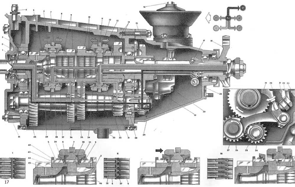
Figure: 17. The scheme of the four-speed transmission.
1. Drive shaft;
2. Driven shaft;
4. Breather;
5. Toothed ring of the IV gear synchronizer;
6. Sliding clutch for synchronizer of III and IV gears;
7. Fork of switching of III and IV gears;
8. Gearbox housing;
9. Gear wheel and ring gear of the 3rd gear synchronizer;
10. Gear wheel and ring gear of the 2nd gear synchronizer;
11. Shift fork for 1st and 2nd gears;
12. Hub of the synchronizer clutch for 1st and 2nd gears;
13. Sliding clutch for synchronizer of 1st and 2nd gears;
14. Gear wheel and ring gear of the 1st gear synchronizer;
15. Reverse gear;
17. The leading gear wheel of the speedometer drive;
18. Flange of elastic coupling;
19. Reverse gear fork;
20. Stem of the fork for reverse gear;
21. Rod of the fork for engaging III and IV gears;
22. Stem of the fork for engaging 1st and 2nd gears;
23. Limiting screw for engaging 1st and 2nd gears;
24. Intermediate shaft;
25. Intermediate shaft reverse gear;
26. The axis of the intermediate reverse gear;
28. Driven gear wheel of the speedometer drive;
29. Rear cover of the transmission;
30. Bushing of gear wheel of 1st transfer;
31. Gear wheel I transfer of the intermediate shaft;
32. Locking ring of the 1st gear synchronizer;
33. Drain plug;
34. Locking ring of the 2nd gear synchronizer;
35. Gear wheel of the II transfer of the intermediate shaft;
36. Gear wheel of III transfer of intermediate shaft;
37. The blocking ring of the synchronizer of the III transfer;
38. Hub of the coupling of the synchronizer of III and IV transfers;
39. Locking ring of the IV gear synchronizer;
40. Gear wheel of constant engagement of the intermediate shaft;
41. Clutch housing;
42. Spring of the blocking ring of the synchronizer;
43. Thrust washer spring;
44. Belleville spring;
45. Retaining ring of the synchronizer hub;
46. \u200b\u200bRetaining ring of the blocking ring of the synchronizer;
I. Neutral position;
II. Start of engaging the 3rd gear;
III. Full engagement of III gear.
Let's analyze the torque transmission schemes when engaging various gears.
With the gear lever in neutral position, the engine running and the clutch engaged (clutch pedal not depressed), the torque from the drive shaft -1- is transmitted to the intermediate shaft -24- via constant mesh gears -3- and -40-. From the drive gears -31-, -35- and -36- of the first, second and third gears of the intermediate shaft, the torque is transmitted to the gears of the same name of the driven shaft, but none of these gears has a rigid connection with the driven shaft and cannot directly transmit torque moment. The gears are connected to the shaft through the parts of the synchronizers.
When the 1st gear is engaged, the synchronizer clutch -13- connects the small rim of the gear -14- with the hub -12-. In this case, the torque is transmitted through the gear -14-, the clutch -13- and the hub -12- to the driven shaft -2-. When the second gear is engaged, the clutch -13- connects the toothed rim of the synchronizer of the gear -10- with the hub -12- and the torque to the driven shaft will be transmitted through the gear -10-, the clutch -13- and the hub -12-. Similarly, the transmission of torque occurs when the third gear is engaged, only through the toothed ring of the gear -9-.
When the fourth gear is engaged, the synchronizer clutch -6- connects the ring gear -5- of the drive shaft -1- with the synchronizer hub -38- and the torque is transmitted directly from the drive shaft -1- to the driven shaft -2-. Therefore, this transmission is called direct.
To engage the reverse gear, the gear shift lever is moved to the right, then recessed down so that the protrusion of the gear shift lever does not rest against the guide cup, and move back. At the same time, the rod -20- through the fork -19-, moving the reverse gear -27-, engages it with the gears -15- and -25-. Torque is transmitted to the driven shaft through three gears: -25-, -27- and -15-. Therefore, the driven shaft will rotate in the opposite direction.
When the reverse gear is engaged, the rod -20- of the reverse fork presses on the rod of the reverse switch, and the lamp circuit of the reversing light is closed in it. White color the lantern signals that the reverse gear is engaged.
The axial forces arising from the operation of the gearbox are absorbed by the ball bearings of the shafts, which are fixed in their seats and on the shafts with locating and retaining rings.
All forward gears are synchronized. The principle of operation of the synchronizer when the III gear is turned on is shown in diagrams I, II, III.
In neutral position (diagram 1) the locking rings -37- and -39- are spring pressed against the circlips -46-. There is a gap between the tapered surfaces of the locking rings and the coupling -6-, and the teeth of the locking rings are located in the cavities of the gear rims -5- and -9- of the synchronizers. The torque from the ring gear -9- is not transmitted through the locking ring to the clutch -6-.
At the beginning of engaging the 3rd gear (diagram II), the sliding clutch -6-, moving along the splines of the hub -38-, is pressed by its cone against the tapered surface of the locking ring -37-. Friction occurs between the tapered surfaces, as a result of which the locking ring rotates through a small angle (circumferential travel from 2.5 to 5 mm). In this case, the lateral bevels of the locking ring teeth abut against the lateral bevels of the rim teeth -9- and further rotation of the ring stops. At the same time, resistance is created to further axial movement of the coupling -6-. This will continue until the speed of rotation of the slave and intermediate shaft gearboxes. The equalization of the speeds of rotation of the shafts occurs due to friction between the locking ring and the synchronizer sleeve -6-.
When the III gear is fully engaged (scheme III), when the rotation speeds equalize, the friction force between the conical surfaces of the coupling -6- and the ring -37-, as well as between the bevels of the locking ring and the crown -9-, will decrease, and the locking ring, sliding along bevels of the rim teeth -9-, will move along with the clutch along the teeth of the synchronizer rim. In this case, the clutch 6 will connect the gear wheel of the 3rd gear with the hub -38-, and a shockless engagement of the 3rd gear will occur.
The service life of synchronizers largely depends on the completeness of the clutch release. Therefore, it is important to completely disengage the clutch when changing gears.
The locking device for four- and five-speed gearboxes is of the same type and interchangeable. It works as follows: when engaging, for example, reverse gear, the rod -35- (see Fig. 16), moving, squeezes out of its socket the adjacent cracker -34-, which enters the rod socket -33- and at the same time through the middle cracker presses the other side cracker against the stem seat -32-. This will lock the rods -32- and -33- in their neutral position. Similarly, any other two rods are locked when any other gear is engaged.
Gearbox parts are lubricated with TAD-14i gear oil, which is poured into the crankcase through the hole closed with a plug -2-; the capacity of the four-speed gearbox is 1.35 liters. The oil level is checked on a cooled box when all the oil has drained from the crankcase walls and gears. To check the oil level, unscrew the plug -2-, the oil level should be at the lower edge of the hole. Drain the used oil through the hole in the lower gearbox cover. It is closed with a plug -71- with a magnet.
When the parts of the retainers, locking rings, rims and synchronizer couplings are worn out, it is possible that the gears are engaged unclearly and even spontaneously disengaged. The wear of these and other parts occurs during prolonged use of the gearbox or when shifting gears when the clutch is not fully disengaged. In this case, a partial transmission of torque continues through the gears, and when they mesh, the teeth of the gears experience shock loads. Particularly intensive wear of parts occurs when the oil level decreases or it completely leaks. This malfunction is possible when the seals of the drive and driven shafts are worn or the lower or rear covers of the gearbox are loosened. With extreme wear of parts, noise in the gearbox occurs. In the event of this malfunction, further operation of the car is not allowed, as damage to the transmission parts is possible.
In order to prevent premature failure of the gearbox, you should regularly, every 10,000 km, check and, if necessary, add oil, as well as visually check for oil leaks. During the operation of the gearbox, the oil "ages" due to the influence of temperature, transmitting loads and oxidation, so it should be replaced every 60,000 km.
TRANSMISSION VAZ-2107 (FIVE-STAGE)
The five-speed gearbox is created on the basis of a four-speed gearbox and differs in appearance by the shape of the rear cover, in the cavity of which the fifth stage is located at the end of the driven shaft. The introduction of an additional fifth gear expanded the speed range of the vehicle, due to which the engine operates in the most economical modes, as well as improves the engine operating conditions. This, in turn, increases the durability of its work.
The gear ratios of the gears of the same name are the same for five- and four-speed gearboxes. The gear ratio of the fifth gear is 0.82. The capacity of the gearbox housing is slightly higher - 1.55 liters.
Due to the fact that the five-speed gearbox is designed on the basis of a four-speed gearbox, many of its parts have the same structure and are interchangeable. The gearbox is also three-shaft, that is, it consists of a leading -1-, driven -1-8 and intermediate -55- shafts. The drive shaft is identical in design to the four-speed gearbox shaft. The driven shaft is distinguished by its rear part, on which the parts of the fifth stage are located. The intermediate shaft differs in that it has a threaded hole in the rear end for the bolt for fastening the block -46- of the fifth gear and reverse gear.
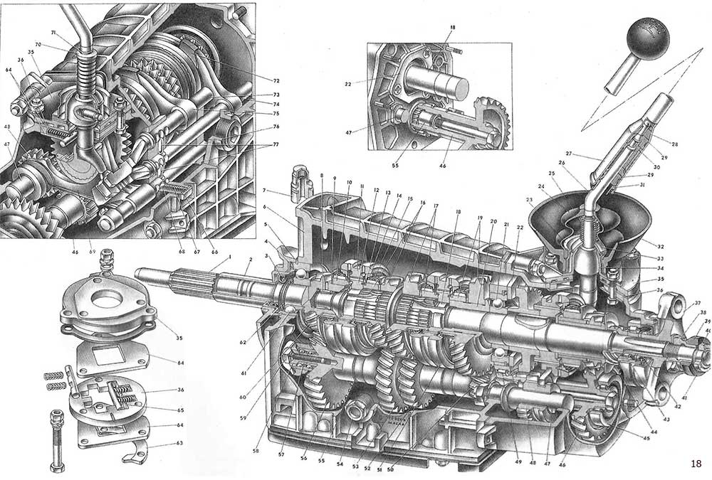
Figure: 18. Gearbox VAZ-2107 (five-speed).
1. Drive shaft;
2. Front cover of the transmission;
3. Drive shaft oil seal;
4. Spring washer;
5. Bearing alignment ring;
6. Gearbox housing;
7. Breather;
8. Needle bearing of the driven shaft;
9. Thrust washer of the synchronizer spring;
10. Toothed ring of the IV gear synchronizer;
11. Sliding clutch for synchronizer of III and IV gears;
12. Hub of the synchronizer clutch for III and IV gears;
13. Retaining ring of the synchronizer;
14. The blocking ring of the synchronizer;
15. Synchronizer spring;
16. Gear wheel and ring gear of the 3rd gear synchronizer;
17. Gear wheel and ring gear of the 2nd gear synchronizer;
18. Driven shaft;
19. Gear wheel and ring gear of the 1st gear synchronizer;
20. Bushing of gear wheel of 1st transfer;
21. Intermediate bearing of the driven shaft;
22. Locking plate of the intermediate bearing;
23. Flange;
24. Protective case;
25. Spring;
26. Gear shift lever;
27. Rod of the gear lever;
28. Elastic damper pad;
29. Damper rubber bushing;
30. Damper spacer sleeve;
31. Damper locking sleeve;
32. Cuff;
33. Spherical washer;
34. Lever ball joint;
35. Gear shift lever housing;
36. Guide plate;
37. Flexible coupling flange cardan transmission;
38. Nut;
39. Centering ring seal;
40. Centering ring;
41. Retaining ring;
42. Oil seal of the back bearing of the driven shaft;
43. Rear bearing of the driven shaft;
44. The leading gear wheel of the speedometer drive;
45. Gear block bearing;
46. \u200b\u200bBlock of gears of V transfer and reverse;
47. The axis of the intermediate reverse gear;
48. Reverse intermediate gear;
49. Rear bearing of the intermediate shaft;
50. Gear wheel of the first transfer of the intermediate shaft;
51. Sliding clutch for synchronizer of 1st and 2nd gears;
52. Gear wheel II transfer of the intermediate shaft;
53. Gear wheel of the III transfer of the intermediate shaft;
54. Plug of filler and control hole;
55. Intermediate shaft;
56. Intermediate shaft constant meshing gear;
57. Front bearing of the intermediate shaft;
58. Clamping washer of the intermediate shaft bearing;
59. Bolt, clamping washer;
60. Gear wheel of constant engagement of the drive shaft;
61. Rear bearing of the drive shaft;
62. Retaining ring;
63. Reversing locking bracket;
64. Washers of the guide plate;
65. Guide bar;
66. Cover for clips;
67. Retainer spring;
68. Clamp;
69. Fork of inclusion of V transfer and reverse;
70. Thrust washer;
71. Retaining ring;
72. Fork of switching of III and IV gears;
73. Rod of the plug of inclusion of the 1st and 2nd gears;
74. Rod of a fork of inclusion of III and IV transfers;
75. Fork of inclusion of I and II transfers;
76. Rod of the fork of inclusion of V transfer and reverse;
77. Blocking rusks.
Driven gears -16-, -17-, -19-, third, second and first gears, parts of synchronizers, shaft bearings are unified with the same parts of a four-speed gearbox. Thus, the design of the parts located in the cavity of the box crankcase is the same as for a four-stage box (see Fig. 16).
Fifth gear and reverse gear parts are located in the rear cover cavity. Together with the driven gear -12- (see Fig. 19) of the reverse gear, the hub -13- of the clutch -14- of the fifth gear synchronizer is attached to the driven shaft -2- with one key. Behind the hub -13- there is a thrust washer and a bushing -18-, on which the gear -17- of the fifth gear rotates. An oil deflector washer -19- is clamped between the pinion sleeve -17- and the drive pinion -20- of the speedometer drive. It reduces oil ejection towards the oil seal -42- (see fig. 18), improving its working conditions. The rear end of the driven shaft rotates on a cylindrical roller bearing -43-, because the load on the rear end of the shaft has increased. The flange - 37 - of the elastic coupling is attached to the splines of the shaft. All parts located on the driven shaft are tightened with a nut 38, which is fixed with a lock washer. On the cylindrical collar of the nut there is a rubber seal -39-, and at the end of the shaft there is a centering ring -40- and its retaining ring.
On the splines of the intermediate shaft -55-, the block -46- of the fifth gear and reverse gear is fastened with a pinch bolt. The rear support for the gear block is a cylindrical roller bearing -45-. The gear block has two rims. The large crown is in constant mesh with the fifth gear driven gear. The intermediate gear -48- engages with the small rim when reverse gear is engaged. The idler gear -48- is located on the axle -47-, which is fastened in the bulkhead of the crankcase with a nut with a washer spring washer. The other end of the axle rests on the rear cover socket.
The shift drive is also slightly different from the four-speed transmission. The design of the rod -76- and the fork -69- for engaging the reverse and fifth gears has been changed. On the rod -76- a double fork -69- is fastened with a locking bolt - one enters the groove of the intermediate gear -48- reverse, the other into the annular groove of the fifth gear synchronizer clutch. That is, when moving the rod -76-, the same fork will engage one or another gear. In this regard, in the rod -76-, the same as on the other rods, three seats for the balls of the retainers are made. Fork -69- has a groove into which the lower end of the gear lever fits. At the end of the rod -76-, a head is attached with a locking bolt, on which a flat is made, with which the head acts on the rod (ball) of the reversing light switch. In the future, when changing the design of the drive, it is planned, together with the rod head, to make a tide with a groove under the lower end of the gear lever, removing this tide from the fork-69-.
A new mechanism has been introduced into the gear change drive - gear selection. It blocks the accidental engagement of reverse gear when the fifth gear is disengaged (see the gearshift diagram on the head of the lever).
The gear selection mechanism consists of a guide plate -36- of the lever, upper and lower washers -64- of a guide plate, a housing -35- of a gearshift lever, a locking bracket -63- for reverse. The listed parts are tightened with three bolts that secure the selection mechanism to the socket of the rear transmission cover.
In the grooves of the guide plate -36-, spring-loaded guide strips -65- are installed, between which the lower end of the gear lever is clamped. Under the action of the springs of the guide plates, the gear shift lever is set to the neutral position, in which the end of the lever is located in the groove in the head of the rod -74- for engaging the III and IV gears.
When disengaging the 5th gear, if the lever goes over the line of neutral position, the protrusion of the lever rests against the bent tab of the locking bracket -63- and further movement of the lever towards the reverse gear stops. This eliminates the accidental engagement of reverse gear while the vehicle is in motion and damage to the transmission parts. To engage reverse gear, push the lever down to compress its spring. In this case, the projection of the gear lever falls below the tab of the locking bracket -63- and it will be possible to move the gear lever back to full inclusion reverse gear.
...DIAGRAM OF THE FIVE-STAGE TRANSMISSION VAZ-2107
The five-speed gearbox is created on the basis of a four-speed gearbox, therefore, the schemes for transmitting torque from the drive shaft to the slave in all gears, except for the fifth gear and reverse, are similar to the four-speed gearbox. That is, the torque from the engine crankshaft is transmitted through the clutch to the drive shaft -1- and through the constant-mesh gears -3- and -39- to the intermediate shaft.
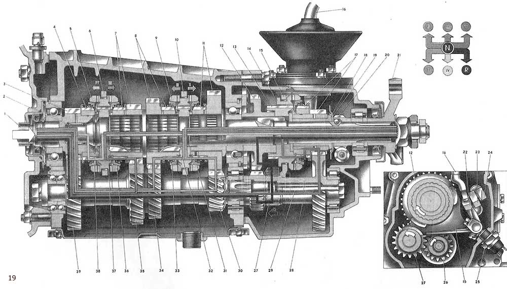
Figure: 19. Scheme of the five-speed gearbox.
I. Drive shaft;
2. Driven shaft;
3. Gear wheel of constant engagement of the drive shaft;
4. Toothed ring of the IV gear synchronizer;
5. Sliding clutch for synchronizer of III and IV gears;
6. Fork of inclusion of III and IV transfers;
7. Gear wheel and ring gear of the 3rd gear synchronizer;
8. Gear wheel and ring gear of the 2nd gear synchronizer;
9. Sliding clutch for synchronizer of 1st and 2nd gears;
10. Fork of inclusion of I and II transfers;
11. Gear wheel and ring gear of the 1st gear synchronizer;
12. Reverse gear;
13. Hub of the V-gear synchronizer clutch;
14. Sliding clutch of the 5th gear synchronizer;
15. Fork of inclusion of V transfer and reverse;
16. Gear shift lever;
17. Gear wheel and ring gear of the 5th gear synchronizer;
18. Bushing of a gear wheel of the V transfer;
19. Oil deflector washer;
20. The leading gear wheel of the speedometer drive;
21. Elastic coupling flange;
22. Stem of the fork for switching on the V gear and reverse;
23. Rod of a fork of inclusion of III and IV transfers;
24. Stem of the fork for engaging 1st and 2nd gears;
25. Reversing light switch;
26. Reverse gear of the gear block;
27. Intermediate reverse gear;
28. Block of gears of the V transfer and reverse;
29. The axis of the intermediate reverse gear;
30. Gear wheel of the I transfer of the intermediate shaft;
31. Locking ring of the 1st gear synchronizer;
32. Hub of the synchronizer clutch for 1st and 2nd gears;
33. Locking ring of the 2nd gear synchronizer;
34. Gear wheel II transfer of the intermediate shaft;
35. Gear wheel of III transfer of the intermediate shaft;
36. The blocking ring of the synchronizer of the III transfer;
37. Hub of the synchronizer clutch for III and IV gears;
38. The blocking ring of the IV gear synchronizer;
39. Intermediate shaft constant meshing gear.
The block of gears of the intermediate shaft has constant meshing with the gears -7-, -8-, -11- of the third, second and first gears of the driven shaft. Therefore, they rotate from the intermediate shaft both when the gear is engaged and when the gear is disengaged. In addition, together with the intermediate shaft, the gear block -28- rotates, from the large rim of which the rotation is transmitted to the gear -17- of the fifth gear. Since the gears -7, 8, 11, 17- are loosely seated on the driven shaft -2-, then when the gear lever is in the neutral position, none of these gears transmits torque to the driven shaft.
When starting off and overcoming difficult sections of the road, 1st gear is engaged (see the diagram of movement of the gear shift lever -16-). In this case, the sliding sleeve -9-, engaging with the toothed rim of the synchronizer of the gear -11- of the first gear, connects the hub -32- with the gear -11-. The torque from gear -11- is transmitted through clutch -9- and hub -32- to driven shaft -2-. The transmitted torque increases in accordance with the gear ratio by 3.67 times.
With further acceleration of the car, they switch from first gear to second. In this case, the clutch -9- connects the middle / pizza -32- with the toothed rim of the gear -8- of the second gear, and the torque from the gear -8- through the clutch -9- and the hub -32- is transmitted to the driven shaft. The magnitude of the torque is slightly reduced and will be increased by 2.10 times in comparison with the direct drive; the vehicle speed increases.
When shifting to third gear, the sliding sleeve -5- of the other synchronizer connects the hub -37- with the rim of the gear -7-. The torque is transmitted from gear -7- via clutch -5- and hub -37- to driven shaft -2-. The amount of torque decreases slightly, and the speed increases.
When the fourth gear is engaged, the clutch -5- meshes with the gear rim -4- of the drive shaft, that is, it directly connects the drive and driven shafts of the gearbox. In this case, the rotational speed of the driving and driven shafts will be the same, and the amount of torque does not change. This transmission is called direct.
When the fifth gear is engaged, the sliding clutch -14- connects the hub -13- with the ring gear -17-. The torque will be transmitted from the drive shaft -1- via the constant mesh gears -3- and -39- to the intermediate shaft. From it to the block -28- gears and from the large crown of the block to the driven gear -17- of the fifth gear, then through the clutch -14- and the hub -13- to the driven shaft -2.- In this case, the magnitude of the torque will be minimal, and the speed maximum.
Reverse gear It is activated by moving the gear lever to the right, then pushing it down and moving it backward in the direction of the vehicle. In this case, the intermediate gear -27- of the reverse gear meshes with the small rim -26- of the gear block and with the rim of the gear -12- of the reverse gear. When moving the intermediate gear -27-, the rod head presses the ball of the switch rod -25- and sinks it. The reversing lamp circuit is closed and the lamp signals white about the engaged reverse gear.
When the gear is engaged, when the driven shaft -2- rotates, the rotation is transmitted to the drive gear -20- of the speedometer drive. From it, the rotation is transmitted to the driven gear wheel of the speedometer drive and through a pair of helical gears to the drive shaft of the speedometer cable; the cable drives the speedometer.
Gearbox parts are lubricated with TAD-17i gear oil, which is poured in an amount of 1.55 liters. As the shafts and gears rotate, oil mist is formed. Oil through the radial holes in the driven gears - 7, 8, 11 and 17 - enters the landing collars of the driven shaft, on which these gears are located. Due to the grooves on these bands, an oil film is formed, which prevents direct contact between the metal surfaces of the gears and the shaft.
The tightness of the gearbox housing is ensured by the oil seals of the drive and driven shafts and gaskets, which are installed between the crankcase and the bottom and rear covers. To reduce the oil pressure on the output shaft oil seal, an oil deflector washer -19- is installed on the shaft.
Axial forces arising from the transmission of torque through helical gears are perceived by the ball bearings of the shafts, which are fixed in their seats by locating rings (intermediate bearing of the driven shaft with a lock plate), and on the shafts by spring washers and locking rings.
Simple construction gearboxes, constant mesh helical gears and synchronizers ensure long-lasting and quiet operation of the gearbox. Its maintenance is kept to a minimum: checking the oil level and changing the oil (see fig. 17).
DRIVE GEAR 2107
The rear axle of the car has an elastic connection with the body through parts and assemblies rear suspension... As a result, it constantly fluctuates while driving. Therefore, the angle at which torque is transmitted from the gearbox to the rear axle also changes. In addition, as the vehicle dynamics change, the distance between the gearbox and the rear axle also changes. In order to transmit torque to the mechanisms of the rear axle under these conditions, elements that change its length and the angle of inclination of its shafts have been introduced into the cardan transmission. These elements include cardan joints and the splined joint of the cardan shaft.
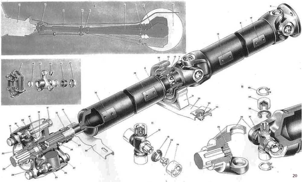
Figure: 20. Cardan transmission.
1. Transmission;
2. Elastic coupling;
3. Front cardan shaft;
4. Support for the propeller shaft;
5. Cardan joint;
6. Rear propeller shaft;
8. Drive wheel car;
9. Flange-plug of the universal joint;
10. Balancing plate;
11. Dirt reflector;
12. Cardan shaft support bearing;
13. Support bearing housing;
14. Support cushion;
15. Splined tip of the front propeller shaft;
16. Oil seal;
17. Bolts for fastening the flexible coupling to the flanges;
18. Retaining ring;
19. Centering sleeve;
20. Centering ring;
21. Centering ring seal;
22. Nut;
23. The driven shaft of the gearbox;
24. Flange of the driven shaft of the gearbox;
25. Metal liner of the elastic coupling;
26. Elastic element of the elastic coupling;
27. Flange of the elastic coupling;
28. Plug of holes for greasing splines;
29. Oil seal holder;
30. Front propeller shaft safety bracket;
31. Support bracket;
32. Cross member of the intermediate support;
33. Spacer sleeve;
34. Rubber bushing;
35. Nut for fastening the universal joint fork;
36. Universal joint yoke;
37. Crosspiece of the universal joint;
38. Needle bearing oil seal;
39. Needle bearing;
40. Retaining ring of the needle bearing;
41. The stuffing box of the radial-mechanical seal;
42. End washer;
I. Cardan transmission scheme;
II. Cardan joint;
III. Crosspiece with radial-mechanical seal stuffing box.
The cardan drive consists of an elastic coupling -2-, front -3- and rear -6- cardan shafts, two cardan joints -5- and an intermediate support -4-. The flexible coupling reduces driveline noise and vibration and allows the transmission of torque at an angle. It connects the driven shaft -23- of the gearbox with the spline -15- of the front propeller shaft -3-. The clutch itself is made of six rubber elements -26- and metal inserts -25-. The rubber elements are vulcanized to the liners. The inserts have holes for bolts -17-, which connect the elastic sleeve to the two flanges. One of them (pos. 24) is seated on the splines of the driven shaft -23- of the gearbox and secured to it with a nut -22-, which is countered by bending the washer onto the edge of the nut. The other flange (pos. 27) is located on the splines of the end piece -15- of the front propeller shaft. Due to the spline connection, the length of the cardan transmission changes.
The elastic coupling is centered on the flanges by six projections of the liners -25-, three of which go into the grooves of the flange -24- of the gearbox driven shaft, and the rest - into the grooves of the flange -27- of the elastic coupling. In the free state, the holes in the liners of the elastic coupling are located on a larger diameter than the holes in the flanges -24- and -27-, therefore, before connecting the coupling with the flanges, it is clamped with a clamp. In this case, the holes in the coupling and in the flanges are centered, and the bolts go into the holes in the coupling and flanges. After removing the clamp, the elastic coupling returns to its original state, thereby achieving an interference fit in bolted joints. The nuts with nylon inserts are screwed onto the bolts of the elastic coupling.
To center the gearbox output shaft -23- and the flange -27- of the flexible coupling, a centering sleeve -19- is pressed into the flange, on which the centering ring -20- of the gearbox output shaft is supported. It is pressed onto shaft -23- and is held there with circlip -18-.
The spline joint is lubricated with the PIOL-1 grease through the hole closed with the plug -28-. This connection is sealed from the outside with a gland -16-, and from the inside of the flange with a gasket -21-, which is pressed against the flange end. Oil seal -16- is located in metal clip -29-, which, after pressing the gland with an axial load of 0.3-0.5 mm, is compressed along the flange groove.
The front propeller shaft -3- is made of a thin-walled steel tube, to the ends of which splined ends are welded. An elastic coupling is located on the slots of the front tip. Rear tip front shaft rests on the ball bearing -12- of the intermediate support- 4-. The bearing is located in a steel housing -13- and is secured in it with a circlip. The bearing of the intermediate support is of a closed type, with seals that reliably hold the lubricant embedded in it during assembly. Additionally, the bearing is protected by two dirt deflectors -11-. To absorb the vibrations of the cardan transmission, the bearing housing is located in a rubber cushion -14-, which is vulcanized to the metal surfaces of the bearing housing and the bracket -31- of the intermediate support. The cushion configuration allows the front propeller shaft to have axial movement in the intermediate bearing.
The intermediate support bracket -31- is fixed to the cross-member -32- with two bolts and nuts, and the intermediate support cross-member is fixed with two bolts which are welded to the body floor. The cross member is fastened with nuts through metal spacers -33- and rubber bushings -34-, which isolate the floor from the cross member. On the splines of the rear end of the propeller shaft, the universal joint yoke -36- is fastened with a nut -35-.
The rear propeller shaft -6- is also made of a thin-walled tube. Universal joint forks are welded to the pipe on both sides. When balancing the driveline, balancing plates -10- are welded to the shafts, with the help of which the imbalance of the driveline is eliminated. To ensure that the factory balance is not disturbed, before disassembling the cardan transmission caused by replacing worn or damaged parts, mark the parts to be divided so that they can be restored to their original position during assembly. An imbalance in the cardan transmission causes vibration and rapid wear of the vehicle's transmission.
Rear propeller shaft -6- is connected to the front cardan shaft -3- and with the drive pinion of the final drive by means of cardan joints. The cardan joint consists of two forks -36-, a crosspiece -37-, needle bearings -39- and parts for seals and locking needle bearings. Both forks of the universal joint are connected by a cross -37-, the pins of which go into the holes of the forks. Needle bearings -39- are put on the spikes of the cross, the cases of which are pressed into the holes of the forks with a force of 800 kgf. The oil seal -38- keeps the grease in the needle bearings and prevents dirt and water from entering them. Each oil seal is housed in a stamped steel cage. The cage assembly with the oil seal is pressed onto the spike spike.
The needle bearing -39- is secured in the yoke bore with a circlip -40-, which is available in five different thicknesses. Each retaining ring size has a specific color: 1.62 mm - yellow; 1.59 mm - black; 1.56 mm - blue; 1.53 mm - dark brown; 1.50 mm - natural. Selecting the retaining ring in thickness, set the axial clearance of the cross in the range of 0.1-0.4 mm. This clearance is required to center the cross in the forks. Retaining rings are selected using a special probe, which has four petals 1.53 mm thick; 1.56 mm; 1.59 mm; 1.62 mm. After pressing one of the needle bearings into the bore of the fork, a retaining ring 1.56 mm thick is installed in the groove and then the other bearing is pressed against the end of the cross (in this case, there is no axial clearance of the cross). A probe is used to measure the distance between the bearing housing and the end of the annular groove. If the petal of the stylus passes through 1.56 mm, then a 1.53 mm thick ring should be installed. If this distance is less than 1.53 mm, then a 1.50 mm thick ring must be installed. If the measured distance is more than 1.62 mm, then the originally supplied 1.56 mm ring should be replaced with a 1.62 mm ring. After installing the circlips, hit the bearings with a plastic hammer. Under the influence of impact and elastically compressed oil seals, the gap between the bottoms of the bearing housings and the retaining rings is selected, and gaps appear between the bearing housings and the ends of the crosspieces. After assembly, the forks of the universal joint should turn easily, without jamming.
For the safety of the vehicle movement, a safety bracket -30- is installed under the front propeller shaft, which prevents the shaft from falling when the elastic coupling is destroyed.
In order to increase the service life of cardan joints, since 1986, bearings of crosspieces of increased accuracy have been produced, with a reduced inter-needle clearance. New and old crosses are interchangeable.
For the same purpose, since 1988, a new cardan transmission has been produced with new hinges of increased durability. Cardan joints of the new design have improved sealing of needle bearings and better protection against dirt, which is achieved by the use of radial-mechanical seals.
The stuffing box -41- has three working sealing surfaces. When installing the needle bearing -39- on the spike spike and pressing it into the hole of the universal joint yoke, one surface of the oil seal is pressed against the end of the needle bearing housing due to the elasticity of the rubber, the other - against the shoulder of the cross, providing an axial seal. And the third surface is pressed against the cylindrical spike, creating a radial seal. Thus, the gland simultaneously seals the end and radial clearances between the crosspiece and the needle bearing.
To prevent friction of the metal end surfaces of the cross studs and stamped bearing housings, end washers -42- made of polyamide are installed between them. This eliminates the possibility of a sharp increase in temperature in the area of \u200b\u200bthe needle bearing and coking of the lubricant in the bearing.
The shanks of the end washers are located in the holes of the spikes of the cross and grease along the grooves of the shanks and the end surfaces of the washers from the holes of the cross goes to needle bearings, that is, there is a constant "replenishment" of the bearings with grease. This improves their working conditions. The introduction of these constructive additions made it possible to increase the durability of the universal joints.
Cardan drive works in the most adverse conditions: in the affected area environment (dirt, moisture) and under constantly changing loads. In order to prevent intensive wear of the hinges under these conditions, in addition to improving the design of the bearing seals, it is important to monitor the tightness of the bearings of the crosses and the intermediate support and to prevent the cardan drive from wobbling, which may occur when the shafts are deformed due to rubbing against road obstacles or loosening the bolts of the forks of the hinges or intermediate support. Balancing imbalance is possible if the rules for assembling the cardan transmission are not followed during its repair.
After long-term operation of the vehicle (over 100,000 km of run), it is recommended to remove the cardan transmission and check the cardan joints for ease and smoothness of turning the forks and for the absence of axial and radial clearances in the bearings of the crosses and intermediate support. It is also necessary to make sure that there are no traces of rubbing against road obstacles on the propeller shafts.
If the rotation of the forks is smooth, there are no jamming and noticeable radial and axial clearances in the bearings and circumferential clearances in the spline connection, and it is not thrown out through the glands of the crosspieces lubricant, then the cardan transmission is suitable for further operation. Otherwise, it is being repaired.
REAR AXLE VAZ-2107
Torque to the rear drive wheels is transmitted through the final drive and differential located in the rear axle of the vehicle. The main gear changes the size and direction of the transmitted torque. In this case, the tractive effort on the drive wheels increases in accordance with the gear ratio of the main drive. The differential allows the driving wheels of the car to rotate at different speeds, which eliminates slippage of one of the wheels when the car is turning or when the car is moving on an uneven section of the road when the wheels travel a path of different lengths.
The rear axle of the car is unified with other models of VAZ cars (with the exception of four-wheel drive vehicle). The rear axles (gearboxes) differ from each other in the final drive ratios. To distinguish gearboxes, markings are applied to their neck: Y - gear ratio 4.4 (for "Universal"); 2 - gear ratio 4.1 for the VAZ-2121 model; without marking - gear ratio 4.3; 3 - gear ratio 4.1; 6 - gear ratio 3.9.
On a VAZ-2107 car, a main gear with a gear ratio of 3.9 is used, and, as an option, a gearbox with a gear ratio of 4.1 can be installed.
The main gear is hypoid, the axis of the drive gear is displaced downward relative to the axis of the driven gear, i.e. the axes do not intersect, but intersect. The shape of the teeth of the gears of such a transmission allows a larger number of teeth to be meshed at the same time, increases the sliding of their working surfaces. All this reduces the load on each tooth and increases the safety margin of the teeth of the final drive gears. The hypoid gear improves the smoothness of the engagement, reduces the noise from the rear axle operation and allows more torque to be transmitted in comparison with the spiral-bevel gear. In addition, the hypoid final drive reduces the height of the driveline and the floor of the body, as a result of which a more comfortable placement of passengers in the body is achieved and the center of gravity of the car is partially shifted, which increases its stability.
The final drive gears are selected based on noise and contact, so they are supplied as spare parts in pairs and separate them, i.e. change one at a time, you can't. The hypoid final drive requires special anti-seize lubricant. Such oil is TAD-17i.
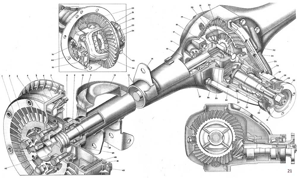
Figure: 21. Rear axle.
1. Bolt of fastening of the brake drum and wheel;
2. Guide pin;
3. Oil baffle of the semi-axle bearing;
4. Brake drum;
5. Cast iron brake drum ring;
6. Rear brake wheel cylinder;
7. Fitting for bleeding brakes;
8. Semi-axle bearing;
9. Locking ring of the bearing;
10. Rear axle beam flange;
11. Semiaxis oil seal;
12. Support spring suspension cup;
13. Rear axle beam;
14. Bracket for mounting the upper suspension bar;
15. Semi-axle guide;
16. Nut of differential bearing;
17. Bearing of the differential box;
18. Cover of the differential box bearing;
19. Breather;
20. Satellite of the differential;
21. Driven gear wheel of the main transfer;
22. Left axle shaft;
23. Semi-axle gear;
24. Rear axle reducer case;
25. Drive gear adjusting ring;
26. Bearing spacer sleeve;
27. Drive gear bearing;
28. Drive gear oil seal;
29. Dirt-reflector oil seal;
30. Cardan joint flange;
31. Nut;
32. Oil deflector;
33. Main gear drive gear;
34. Axis of satellites;
35. Support washer of the semi-axle gear;
36. Differential box;
37. Right axle shaft;
38. Bracket for fastening suspension parts;
39. Semi-axle bearing thrust plate;
40. Rear brake shield;
41. Rear brake shoe;
42. Brake pad friction pad;
43. Half-shaft flange;
44. Bearing nut lock plate;
45. Bolt bearing cover.
The final drive and differential parts are mounted in a separate housing -24-, which is bolted to the rear axle support -13-. To prevent oil leakage in the places where the gearbox housing is attached to the rear axle beam, the bolt thread is lubricated with sealant before screwing in, and a sealing gasket is installed between the adjacent surfaces of the beam and the crankcase.
The main gear consists of a driving gear -33- and a driven gear -21-. The pinion gear is installed in the gearbox housing -24- on two tapered roller bearings -27-. A spacer sleeve -26- is installed between the inner bearing races. The flange -30- is fitted onto the splined end of the pinion gear. It is fastened to the shank with a self-locking nut -31-. An oil deflector -32- is clamped between the front bearing -27- and the flange, which throws oil out of the oil seal -28-. This oil seal is pressed into the throat of the crankcase and with its working edge wraps around the polished cylindrical surface of the flange -30-. To protect the gland from dirt and damage, a dirt reflector -29- is pressed onto the flange.
An adjusting ring -25- is installed between the end face of the pinion gear and the inner ring of the rear bearing, which determines correct position pinion gear -33- in relation to pinion gear -21-. This ring has different thicknesses from 2.55 to 3.55 mm every 0.05 mm. Seventeen sizes of the adjusting ring provide precise alignment of the final drive gears.
To prevent axial displacement of gear -33- under operating loads, a preload is created in its bearings by tightening nut -31-. This deforms the spacer sleeve -26- up to a certain limit. The value of the bearing preload is controlled by a dynamometer according to the torque of the drive pinion turning resistance. The moment should be equal to 16-20 kgf * cm for new bearings and 4-6 kgf * cm for bearings after a run of 30 km or more.
The driven gear -21- is made in the form of a wreath, which is attached to the flange of the differential box with eight self-locking bolts. Together with the differential box, the driven gear rotates in two tapered roller bearings -17-. These bearings are installed in the seats of the rear axle gearbox housing -24- and are closed with covers -13-, which are fixed to the housing -24- with bolts -45-. Threads for adjusting nuts -16- are cut in the seats and bearing caps. These nuts are used to adjust the lateral clearance in the meshing of the final drive gears and the preload in the bearings -17- of the differential. The position of the adjusting nuts is fixed by plates -44-, which are bolted to the differential bearing covers 18. The tabs of the plates fit into the grooves of the adjusting nuts -16- and lock them.
The principle of adjusting the clearance in the meshing of the main gears is as follows. After adjusting the preload in the bearings of the drive gear, the differential box assembly is installed in the gearbox housing, the adjusting nuts -16- are screwed in until they come into contact with the bearing rings and the covers -18- are fixed with a torque wrench of 5.2 kgf * m. Then, with the help of a special device, the lateral clearance between the teeth of the driving gear -33- and the driven gear -21- is adjusted, for which, by turning the adjusting nuts -16-, the differential is moved along its axis. The gap is measured by the indicator of the fixture and should be 0.08-0.13 mm. After that, the nuts -16- are sequentially and evenly tightened and, according to the divergence of the covers -18- (measured by the second indicator of the device), a preload is set in the differential bearings.
The differential is conical, two-satellite. The satellites -20- are mounted on a common axle -34-, which is inserted into the holes in the differential box. The axle -34- is kept from falling out of the holes by the driven gear -21-, which overlaps the axle in the differential box. On the axle, in the places where the satellites are installed, grooves are made for better lubrication of the working surfaces of the satellites and the axle. With their teeth, the satellites are in constant mesh with the teeth of the side gears -23-, installed with their cylindrical belts in the seats of the differential gearbox -36-. Washers -35- are installed between the ends of the side gears and the differential box. By selecting these washers in thickness, a gap of 0-0.1 mm is established between the teeth of the satellites and half-axial gears.
The half-axle gears have holes with splines, into which the spline ends of the half-shafts -22- and -37- enter. These axle shafts transmit torque from the differential to the drive wheels. Outside on the axle shaft there is a flange forged together with the axle shaft. It is bolted to this flange -1- brake drum -4- and disc rear wheel... The outer end of the axle shaft rests on a ball bearing -8- clamped on the axle shaft between the shoulder and the locking ring 9. The ring is pushed onto the axle shaft in a state heated to 300 ° C. The bearing -8- of the half-shaft is installed in the seat of the flange of the beam -13- of the rear axle and is fixed in the seat by the plate -39-. This plate, together with the oil deflector -3- and the brake shield -40-, is fastened with four bolts and nuts to the axle beam flange. So that the oil from the rear axle beam does not pass to the wheel braking mechanism, a semiaxis oil seal -11- is installed in the flange seat. The oil deflector -3- and the grooves at the end of the axle shaft prevent the passage of oil to the brake pads if the oil seal -11- is damaged.
For access to the nuts of the bolts fastening the oil deflector -3-, the shield -40- and the plate -39- to the beam flange, there are two holes in the axle shaft for passing a socket wrench. On the shield -40- installed brake pads and wheel cylinder -6- brake mechanism... A brake drum -4- is installed on the semi-axle landing belt, which is attached to the semi-axle flange with two guide pins -2- and additionally, together with the wheel disc, by bolts -1-. To prevent the drum from "sticking" to the semi-axle flange due to corrosion, during assembly, the semiaxis landing ring and its end adjacent to the drum are covered with graphite grease.
The rear axle beam is welded from two stamped casings, to the ends of which forged flanges -10- are butt welded. In the flanges are machined seats for bearings -8- semi-axles, and holes are made for bolts for fixing the shields rear brakes... At the ends of the beam, support cups -12- of rear suspension springs and brackets for fastening the rods and suspension shock absorbers are welded. The middle extended part of the beam has a through opening. A cover is welded to the rear of the opening, in which the oil filling and control hole is located. It is closed with a cork. The front part of the opening has a machined surface to which the rear axle gearbox housing -24- is attached. There is an oil outlet at the bottom of the beam, closed by a plug.
The cavity of the rear axle beam communicates with the atmosphere through the breather -19-, which excludes an increase in pressure inside the beam and the ingress of water when overcoming water obstacles.
In 1979, the Volzhsky Automobile Plant launched the production of the VAZ-2105, one of the modifications of the classic family. This model is a "long-liver", since its production lasted the longest from the "Classic" - 30 years. It is noteworthy that before the appearance of this model, at first all the predecessors of this family until 1976 were equipped with one single gearbox - even from the VAZ-2101. Since 1976, the checkpoint has been modernized, but it was intended only for the VAZ-2106 and Niva. The main difference lay in the changed gear ratios, later this checkpoint was designated as, a box with an "increased" row.
For the VAZ-2105, the box was redone again, which affected the gear ratios. New checkpoint became "intermediate" in this respect between boxes 2101 and 2106. Subsequently, it was the box from the VAZ-2105 that was left and began to complete all cars, and the production of the first two versions was stopped, and there were two versions of 2105 - at 4 speeds and a five-speed. The index of this box also changed over time - instead of 2105, it began to be labeled as 2107 and 21074 (5-speed).
Gearbox device
In general, the concept of "remaking" the box is not entirely correct, since the device of the VAZ-2105 gearbox with 4 speeds practically did not differ from the same gearbox 2101. Gearbox 2105 is of a three-shaft arrangement, with constant gearing and manual control... Externally, the checkpoint "Kopeyki" and "Five" can be distinguished almost only by the markings on the box body.
The scheme of the VAZ-2105 gearbox with 4 steps is presented below, and structurally it does not differ from the modifications 2101 and 2106:
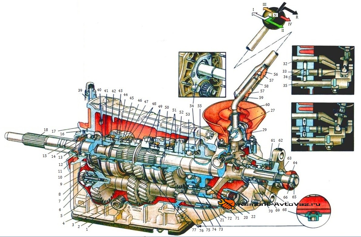
| 1 | Bottom cover; | 40 | Output shaft front end needle bearing; |
| 2 | Filler and control hole plug; | 41 | Synchronizer spring thrust washer; |
| 3 | Toothed wheel of the second gear of the intermediate shaft; | 42 | Fourth gear synchronizer ring gear; |
| 4 | Toothed wheel of the third gear of the intermediate shaft; | 43 | Sliding synchronizer clutch for third and fourth gears; |
| 5 | Intermediate shaft; | 44 | Hub of the sliding clutch of the synchronizer of the third and fourth gear; |
| 6 | Front intermediate shaft bearing; | 45 | Retaining ring for synchronizer; |
| 7 | Clamp washer bolt; | 46 | Synchronizer blocking ring; |
| 8 | Clamping washer of the front bearing of the intermediate shaft; | 47 | Synchronizer spring; |
| 9 | Intermediate shaft constant mesh gear; | 48 | Cogwheel and ring gear of the third gear synchronizer; |
| 10 | Constant mesh gear input shaft; | 49 | Second gear synchronizer gear and ring gear; |
| 11 | Spring washer; | 50 | Secondary shaft; |
| 12 | Retaining ring; | 51 | First gear synchronizer gear and ring gear; |
| 13 | Input shaft rear bearing; | 52 | First gear bushing; |
| 14 | Input shaft oil seal; | 53 | Secondary shaft intermediate bearing; |
| 15 | Front gearbox cover; | 54 | Intermediate bearing lock plate; |
| 16 | Bearing alignment ring; | 55 | Output shaft reverse gear; |
| 17 | Clutch housing; | 56 | Resilient cushion for gear lever damper; |
| 18 | Input shaft of the gearbox; | 57 | Damper rubber bushing; |
| 19 | Reversing light switch; | 58 | Damper spacer sleeve; |
| 20 | Intermediate shaft reverse gear; | 59 | Damper locking sleeve; |
| 21 | Reverse intermediate gear; | 60 | Inner cover for gear lever; |
| 22 | Reverse gear fork; | 61 | Output shaft rear bearing oil seal; |
| 23 | Retractable spring of the gear lever; | 62 | Propshaft flexible coupling flange; |
| 24 | Retaining spring bolt; | 63 | Nut; |
| 25 | Gear lever guide cup; | 64 | Centering ring seal; |
| 26 | Lever ball joint; | 65 | Centering ring retaining ring; |
| 27 | Spherical washer; | 66 | Centering ring; |
| 28 | Spring; | 67 | Output shaft rear bearing; |
| 29 | Gear shift lever; | 68 | Drain plug; |
| 30 | First and second gear shift fork; | 69 | Dirt reflector; |
| 31 | Third and fourth gear shift fork; | 70 | Speedometer drive gear; |
| 32 | Rod of the fork for engaging the first and second gears; | 71 | Speedometer drive; |
| 33 | Rod of the fork for engaging the third and fourth gears; | 72 | Rear gearbox cover; |
| 34 | Blocking rusks; | 73 | Axle of the intermediate reverse gear; |
| 35 | Reversing fork rod; | 74 | Rear intermediate shaft bearing; |
| 36 | Rod retainer ball; | 75 | The gear wheel of the first transfer of the intermediate shaft; |
| 37 | Retainer spring; | 76 | Gearbox housing; |
| 38 | Retainer cover; | 77 | First and second gear synchronizer slip clutch. |
| 39 | Breather; |
Since the box from the VAZ-2105 is structurally similar to the 2101, then kinematic diagram The checkpoint is the same. But the gear ratios are different, on boxes 2105 they are:
- 1st - 3.67;
- 2nd - 2.10;
- 3rd - 1.36;
- 4th - 1.00;
- Back - 3.53;
As for the differences in the device between boxes 2105 and 2101, they boil down mainly to different numbers of teeth on different gears. So, on the intermediate shaft of the gearbox, a 1st speed gear is used with 14 teeth (15 - in 2101), while their angle of inclination is greater. The constant mesh gear of this shaft has 28 teeth (29 - in 2101). The input shaft uses a gear with 18 teeth (19 - for 2101). Due to such features, the shafts with gear blocks at two gearboxes are not interchangeable if you try to install them separately. But in the case of a complex replacement - input shaft together with the intermediate, and all the gear blocks, the installation is quite possible. As for the secondary shaft, in modification 2105 it differs from the shaft 2101 by the gear of the first gear (its teeth have a different inclination, although their number is the same, its diameter is also slightly larger).
Difference between 4-speed and 5-speed gearboxes
As noted, the VAZ-2105 was equipped with two boxes - 4 and 5 speeds. At the same time, the 4-speed version was taken as the basis for creating a 5-speed gearbox and slightly modified. Therefore, the gear ratios of the five-speed up to 4th speed are identical, but the added 5th speed has a gear ratio of 0.82. That is, this direct box still has 4th gear.
Let's consider more specifically the differences between the five-step and the four-step on the VAZ-2105, and there are several of them:
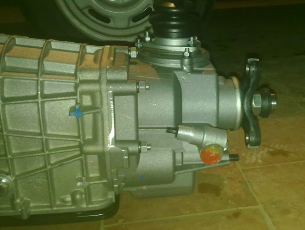
Since a 4-speed version was the basis for creating a 5-speed box, it is quite possible to upgrade the four-speed gear yourself at home, for which you should replace and add the indicated gearbox components.
As for the control of the VAZ-2105 gearbox, the switching scheme does not differ from the VAZ-2106 or any other modification with a 4-speed gearbox. In a 5-speed gearbox, to activate the last speed, it is enough to move the gearbox lever to the maximum to the right and push it forward, that is, in the direction opposite to the rear speed. Below are shown the switching diagrams of both gearbox modifications:
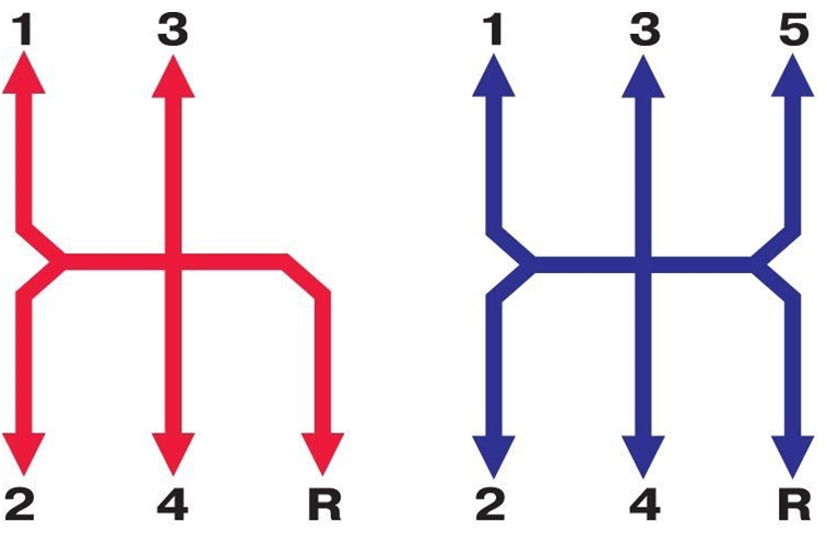
In general, the KPP-2105 is very reliable and capable of working for a long time without any maintenance. In addition, it has good maintainability and it is not so difficult to carry out repairs. Replacing the gearbox 2105 is usually done in case of wear seats bearings in the housing or if it is damaged - breakdown, cracks. In case of other breakdowns (wear or damage to gears, bearings, shafts, etc.), it is possible to restore the unit's performance by replacing broken elements.
Also, replacement can be performed if a 5-speed modification is installed instead of a 4-speed one, in the case when the unit was purchased as an assembly, and not only those elements that allow you to upgrade the old gearbox.
But in any case, it is a replacement, modernization or repair, nothing is impossible to do while the checkpoint is installed on the car. In any case, the node will have to be dismantled, and you need to know how to remove the box.
Dismantling the gearbox from the car
In fact, dismantling the gearbox from the VAZ-2105 is not a very difficult operation and it is quite possible to do it yourself, having only a basic tool:
- Sets of keys (open-end, ring), heads with wrenches, extension cords;
- Screwdrivers;
- Rags;
- WD-40 tool;
- Wooden block;
- Jack;
Removing the box must be done on inspection pit or overpass - otherwise it cannot be dismantled. It is noteworthy that the removal technology is identical for all modifications of this car - with a 5-speed gearbox or a 4-speed carburetor version or a VAZ-2105 injector.
The sequence of actions is as follows:
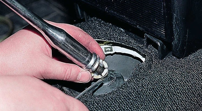
And then the unit is being replaced, modernized or repaired. In the last two cases, the VAZ-2105 gearbox is disassembled, worn elements are replaced, a 5th gear block is added, and so on.
To put the gearbox in place, follow the steps described in reverse order. At the same time, before planting the box, it is recommended to lubricate the splines of the input shaft with a thin layer of Litol to make it easier to enter the driven disc.
When installing it back, if the gearbox does not fit into place, you need to move it back, turn the shaft and try to plant it again. You may need to do this several times to align the splines on the shaft with the splines in the disc.
|
Video - VAZ gearbox repair
|
Leisure - tuning five
|
To repair the VAZ 2107 gearbox, you will need glue, an impact screwdriver, a puller, oil seals for the primary and secondary shafts, gaskets, and a torque wrench.
We carry out repair of the preach box
Repair of the VAZ 2107 gearbox includes the following steps:
2. Dismantle the checkpoint.
3. Clean with a brush and rinse the outer surface of the gearbox with kerosene.
4. Remove the clutch from the checkpoint release bearing and a clutch fork.
5. Disconnect the flexible shaft coupling from the flange on the gearbox output shaft.
6. Remove the flexible coupling flange from the gearbox shaft.
7. Disconnect the engine support with cross member from the rear cover of the gearbox.
9. Remove the reversing light sensor.
10. Remove the cuff from the ball joint of the lever.
11. Using a 10 mm wrench, unscrew the three nuts securing the gear lever housing to the rear crankcase cover.
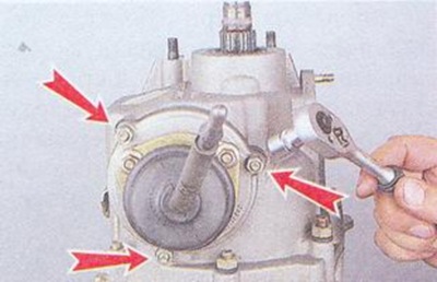
12. Remove the lever housing and the gasket under it from the studs.
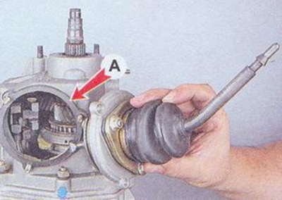
13. Using a 13 mm wrench, unscrew the 2 nuts securing the gas exhaust pipe.
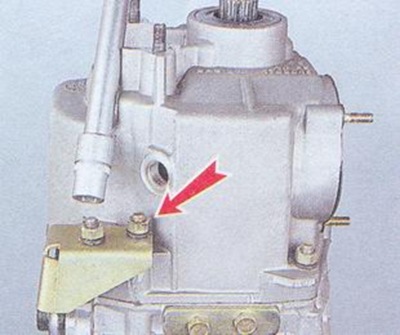
14. Remove the bracket and remove the cage bolt underneath.
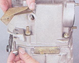
15. Using 13 mm wrenches, unscrew the five nuts of the rear cover.
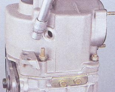
16. Using a 10 mm wrench, unscrew 10 nuts of the bottom cover.
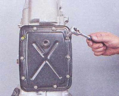
17. Remove the cover and the gasket under it.
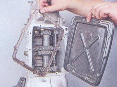
18. If the nuts turned away with the studs, then apply fixing glue and install the studs back.
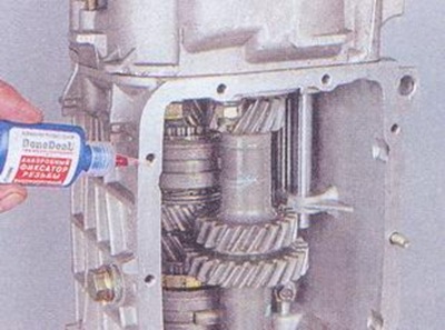
19. Using a 13 mm wrench, unscrew the rear cover fixing nut.
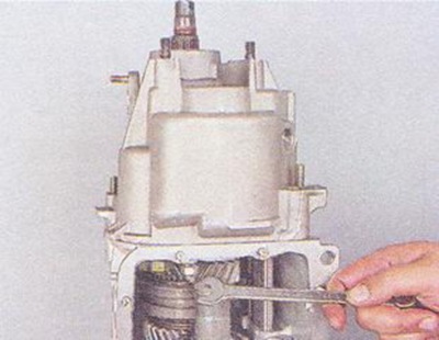
20. Use a screwdriver to drive down rod I and 2nd gear.
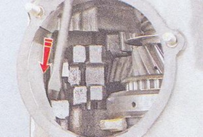
21. Tapping the gearbox cover with a hammer along the perimeter of the mounting plane, disconnect the cover from the gearbox housing.
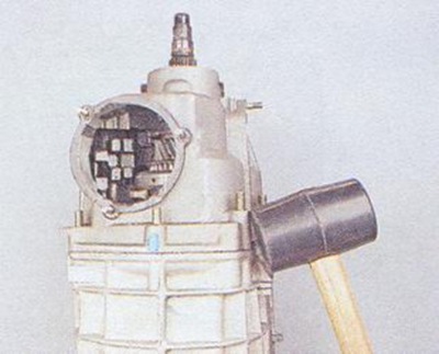
22. Remove the rear cover from the studs.
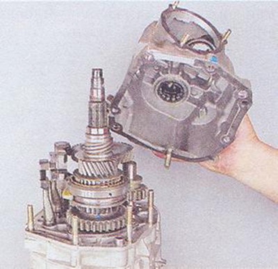
23. Remove the plug of the V-th gear block and reverse gear from the rear cover.
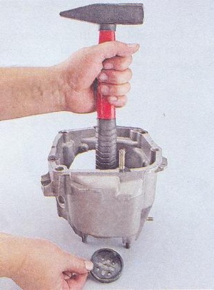
24. With pliers, remove the V-th and reverse gear.
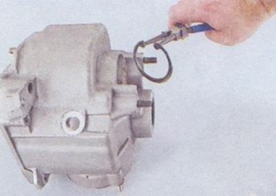
25. Install the rear cover on 2 wooden blocks and press out the block bearing with a hammer V-th gear reverse.
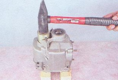
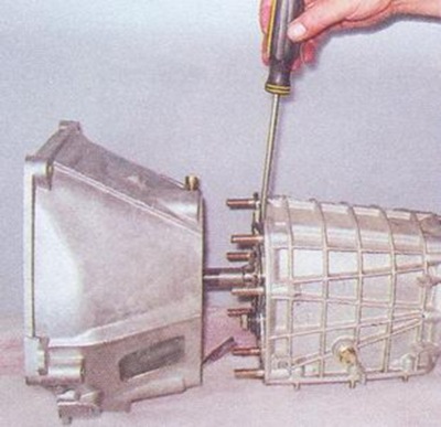
27. To replace the shaft seal, press out the oil seal in the front cover flange of the gearbox.
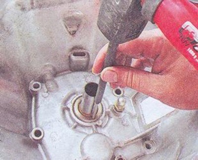
28. Using pliers, remove the oil seal from the front cover of the gearbox.
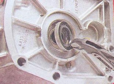
29. Remove the snap ring from the gearbox shaft.
![]()
30. Using a 19 mm wrench, unscrew the bolt of the front shaft bearing and remove the bolt together with the clamping washers.
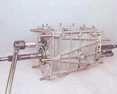
31. Unscrew the gear bolt with a 17 mm wrench.
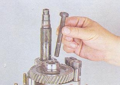
32. Move the 5th gear shift fork and remove the gear block from the shaft.
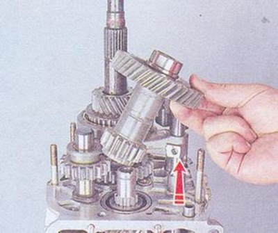
33. Install the gear block in a vice.
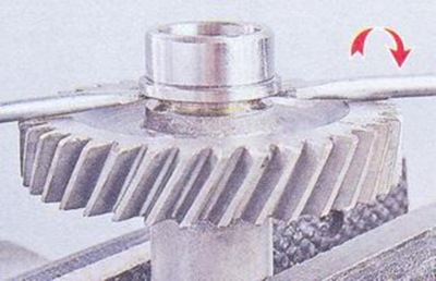
34. Remove the washer from the output shaft.
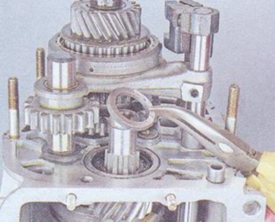
35. Using a 13 mm wrench, unscrew the 2 bolts securing the cover.
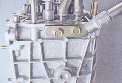
36. Remove the cover with the gasket.
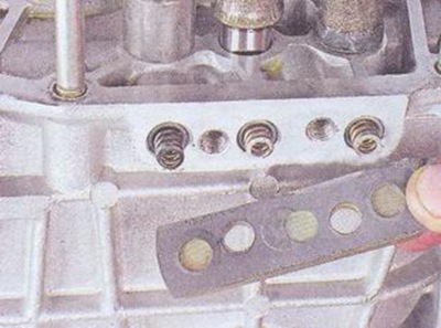
37. In the crankcase, from the holes of the VAZ 2107 gearbox, remove the springs of the rod clamps.
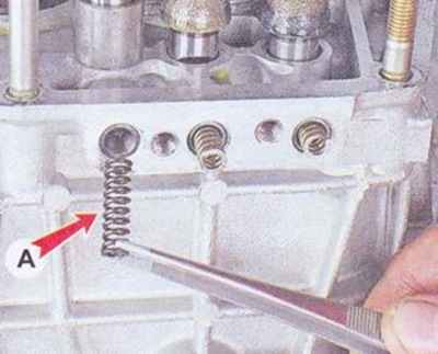
38. It is convenient to remove the locking balls using a rubber bulb, creating a vacuum.
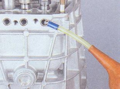
39. Remove the 5th gear with synchronizer from the output shaft.
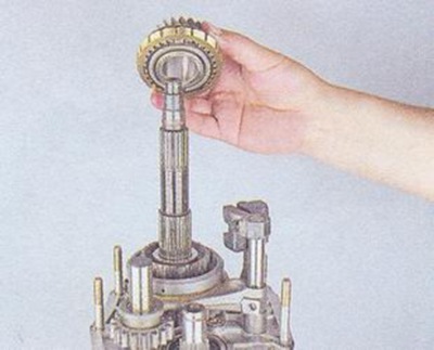
40. Remove the ring.
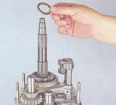
41. Move the gear shift fork, remove clutch V transmission.
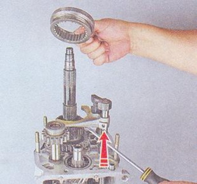
42. Remove the intermediate reverse gear from the axle.
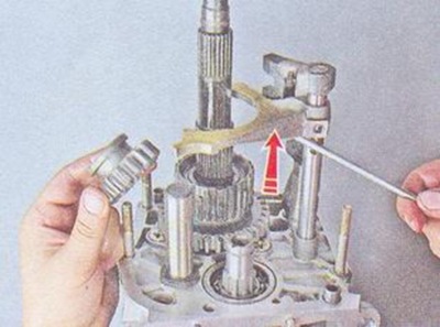
43. Remove the V-th gear and reverse gear engagement rod with the gear shift fork and the rod bushing. Remove the bushing and plug from the stem.
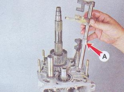
44. Using a 10 mm wrench, unscrew the bolt securing the stem.
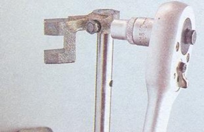
45. Remove the blocking cracker.
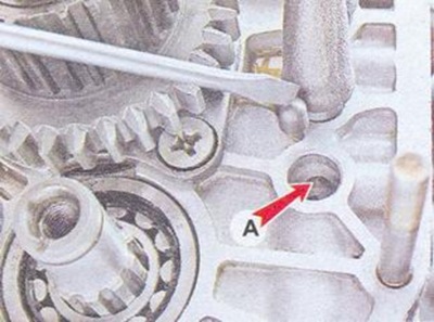
46. \u200b\u200bWe continue to repair the VAZ 2107 gearbox by opening the lock ring V-th transmission.
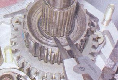
47. Remove the hub from the gearbox shaft.
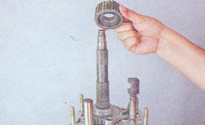
48. Remove the spring washer.
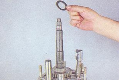
49. Remove the reverse gear.
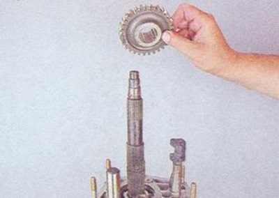
50. Remove the rear shaft bearing.
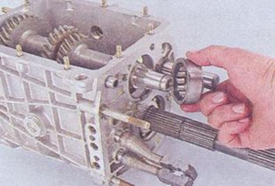
51. Take out front bearing intermediate shaft.
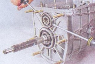
52. Remove the intermediate shaft from the gearbox.
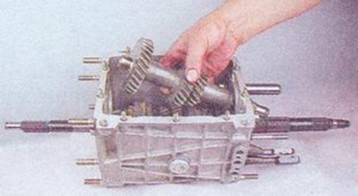
53. Remove part of the rear bearing ring from the shaft.
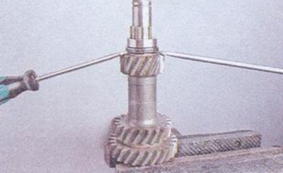
54. Using a 10 mm wrench, unscrew the bolt securing the forks of the 3rd and 4th gears to the rod.
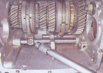
55. Remove the 3rd and 4th gear engagement rod from the hole, remove the plug.
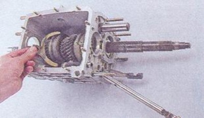
56. Remove the blocking cracker.
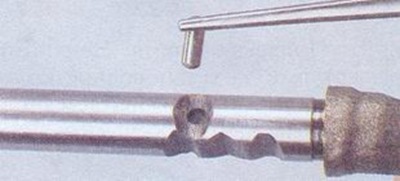
57. Remove the cracker from the hole in the gearbox housing.
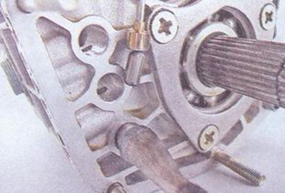
58. Using a 10 mm wrench, unscrew the bolt securing the forks of the 1st and 2nd gears.
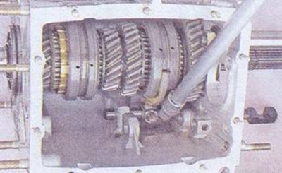
59. Remove the stem from the hole, remove the plug.
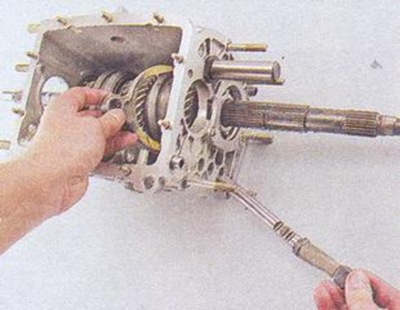
60. Using an impact screwdriver, unscrew the 3 screws of the secondary shaft bearing plate.
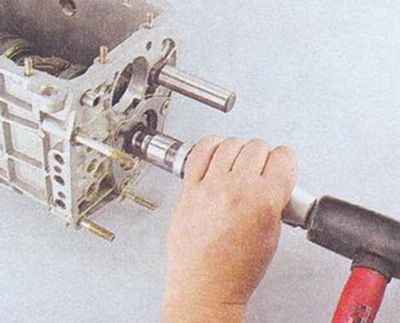
61. Pull the bearing out of the crankcase.
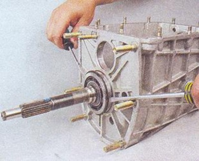
62. Remove the input shaft of the VAZ 2107 gearbox.
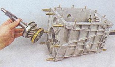
63. Remove the front roller bearing from the shaft.
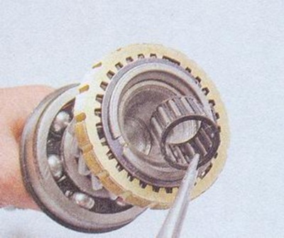
64. Pry with two screwdrivers by the locating ring of the secondary shaft intermediate bearing, pull the bearing off the shaft.
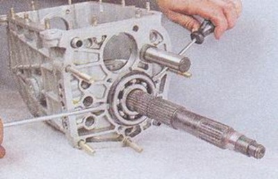
65. Remove the gearbox shaft from the crankcase.
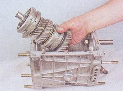
66. Using a 24 mm wrench, remove the reverse gear axle from turning, and unscrew the axle mounting nut by 19 mm.
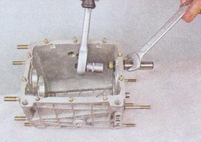
67. Remove the synchronizer of the 3rd and 4th gears from the shaft.
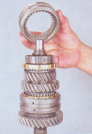
68. Unclench the hubs with pliers and remove them from the shaft.
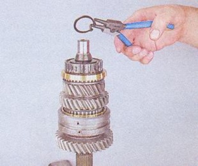
69. Remove the spring washer.
80. Remove the synchronizer clutch hub.
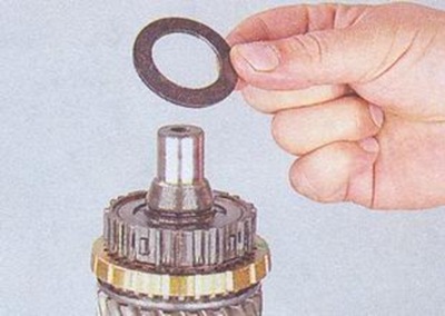
71. Remove the gear wheel from the 3rd gear.
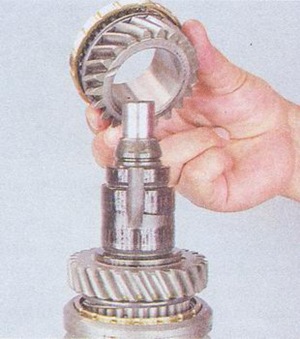
72. Press out the secondary shaft from the gear.
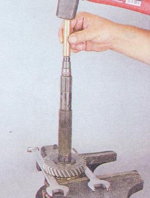
73. Remove the gearbox shaft gear bushing.
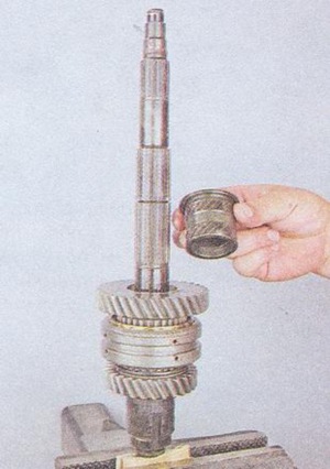
74. Remove the shaft gear from synchronizer I transmission.
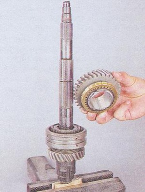
75. Remove the hub of the 1st and 2nd gear clutch.
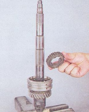
76. Remove the synchronizer sleeve.
![]()
77. Remove the 2nd gear gear from the shaft.
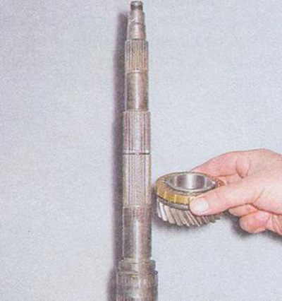
78. Remove the bearing ring.
79. Remove the Belleville washer.
80. Press the input shaft out of the bearing ring.
81. Remove the retaining ring.
82. Release the locking ring and remove the spring of the 4th gear.
The classic five-speed gearboxes have received a number of changes since 2004 or after 2004 and are slightly different from the previous ones.
This should be the teeth. Sharp from top to bottom!
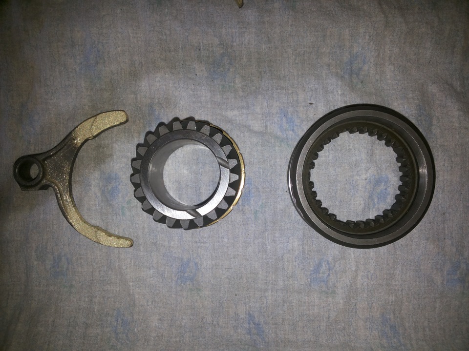
New fork, clutch and gears with 3rd gear synchronizer.
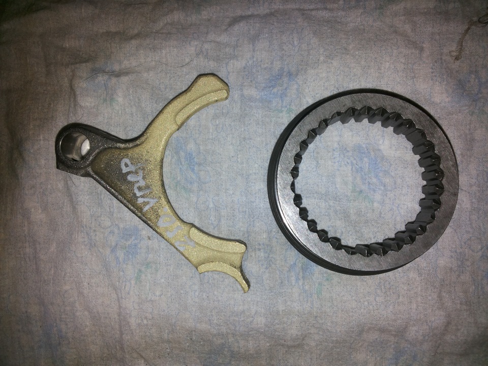
5th gear and reverse gear fork and clutch. Also completely new.
The clutch for 1st and 2nd gears and clutch for 3rd and 4th gears are the same. 5 and reverse clutch is different. It is impossible to confuse them!
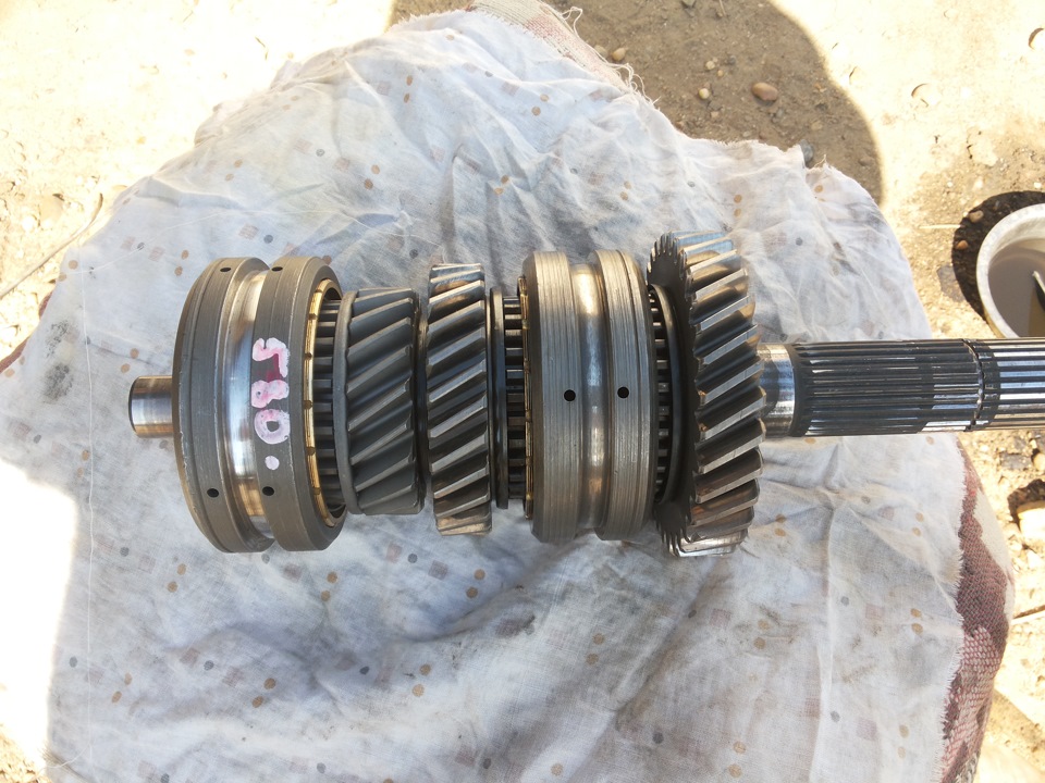
Secondary shaft.
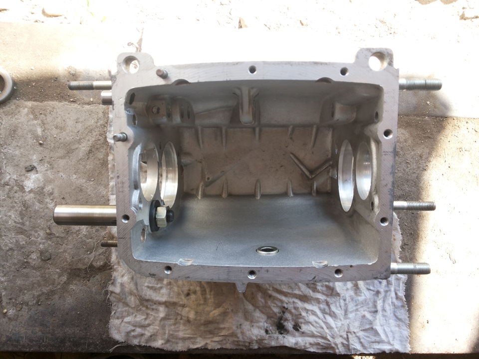
Gearbox housing.
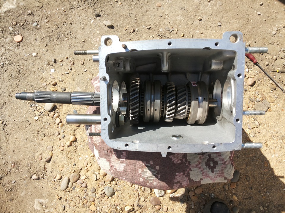
We start the secondary shaft. We install the bearing into the body and fasten the bracket.
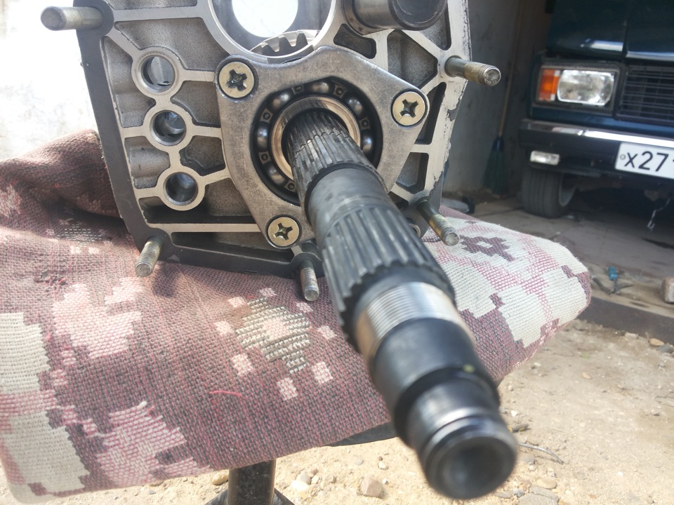
Now we install the input shaft. Do not forget about the circlips, as well as the needle bearing inside the input shaft.
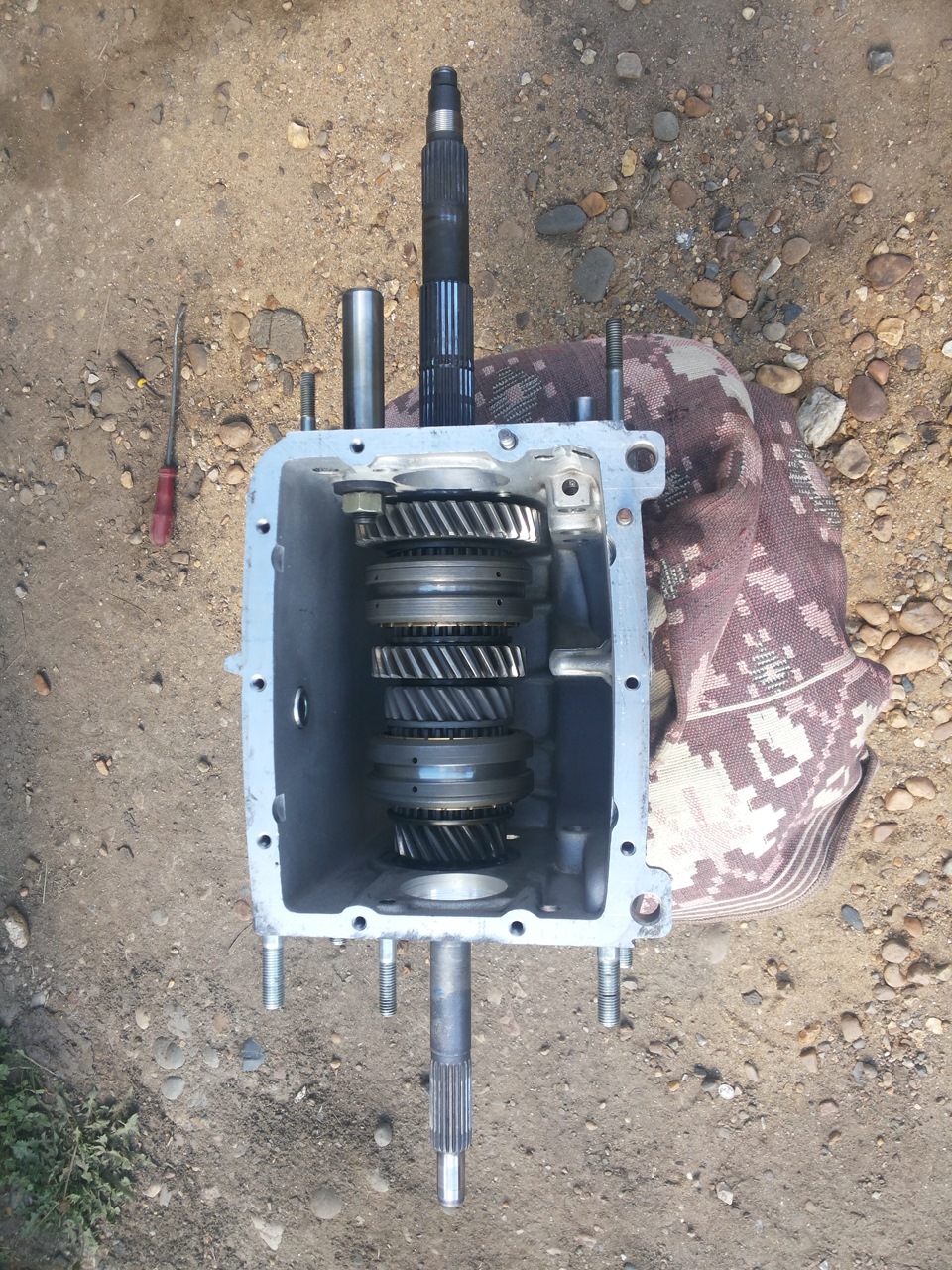
We put the forks 1-2 and 3-4 transfers. The forks are placed with the holes under the bolts up (in this case, the gearbox, pallet up).
We install the rod of the first or second gear, tighten the fork with a bolt (turn the shafts) and put in a long cracker.
We put the fork in 3-4 gears.
Install the third-fourth gear rod. We do not insert it into the plug completely and insert the cracker into the hole in the stem. Push in the stem and tighten the fork bolt. Similarly to the first-second gear ratchet, we install a short rusk.
Now we install the intermediate shaft.
The middle bearing of the intermediate shaft has an inner bearing race, which consists of two parts: a sleeve and a ring. The bushing should be oriented towards the inside of the crankcase.
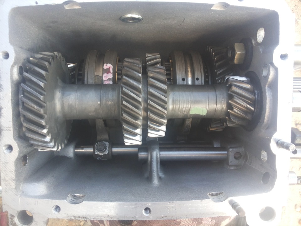
We install bearings. The bearings should not dangle in the box body. Come in tightly. I used a tube with a large thick washer, having an inner diameter just enough to put x on the shaft. And with the help of a hammer, he carefully pressed the bearings.
After installing each next part, we turn the primary and secondary shafts several times. They should rotate without jamming.
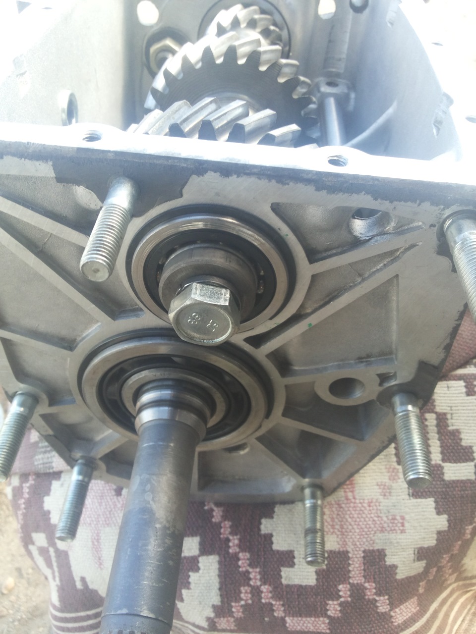
The intermediate shaft bolts are different so do not mix them up. Just remember that the front one with a thick washer, and the rear one without a bolt without a washer and Grover's washer.
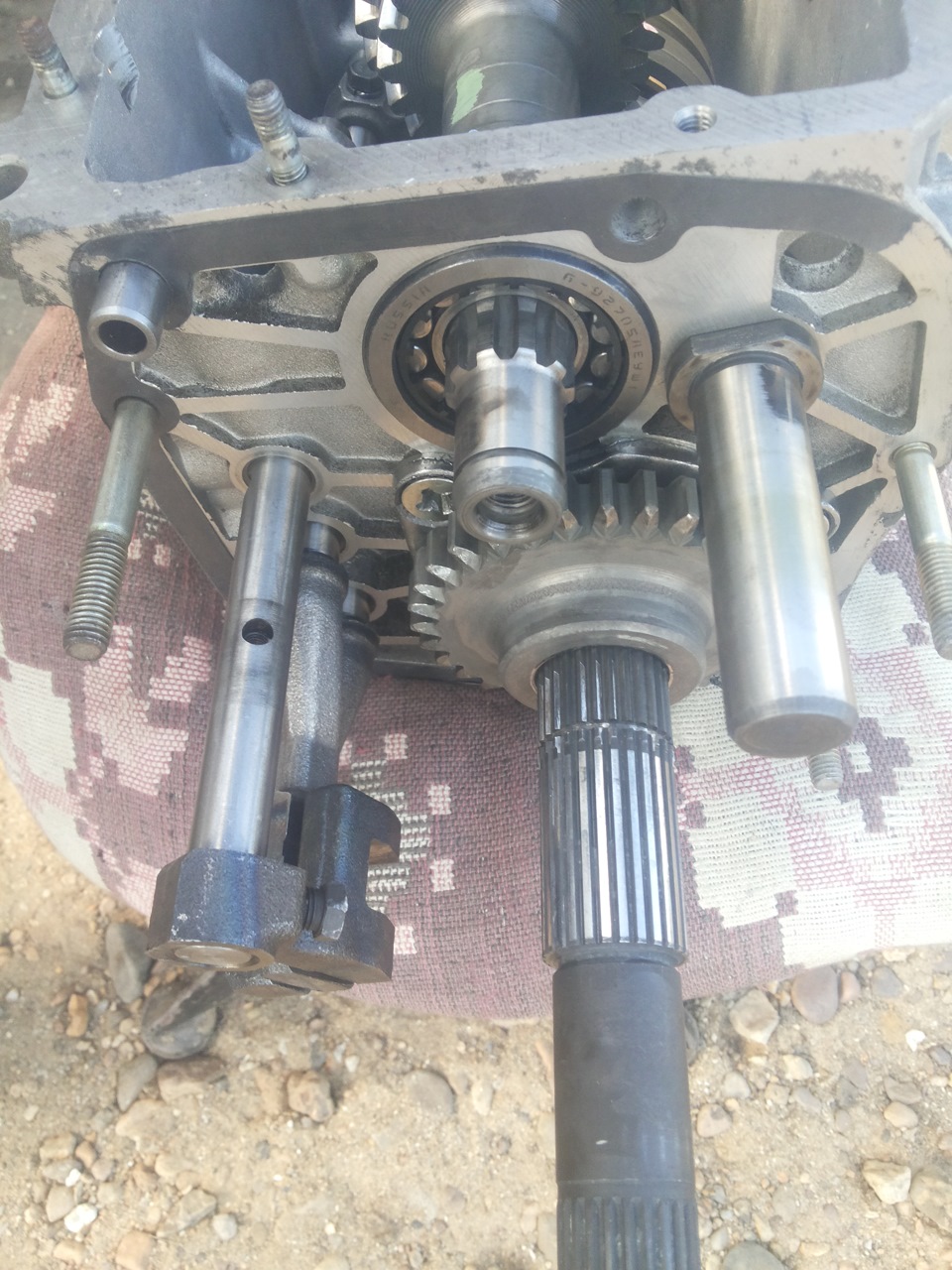
We collect reverse gear and 5th gear.
The design of the car "VAZ 2107" involves the equipment five-speed gearbox gear shifting, circuit diagram which is presented below.
Gearbox device "VAZ 2107"
The designers of AvtoVAZ used the four-speed transmission used on earlier models of the Lada family as the basis for creating the transmission of the "seven". The differences between the new checkpoint are not significant and are expressed in a change appearance and the geometric shape of the rear cover caused by the addition (to the end of the driven shaft) of the fifth stage elements.
The increase in the number of gears provided the following positive aspects during the operation of the car:
Expansion of the range of speed of movement made it possible to operate vehicle in the most economical modes.
The operating period of the power unit has been increased.
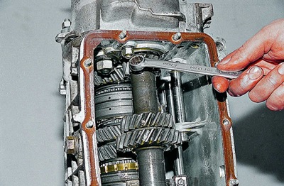
The introduction of an additional gear did not change the value gear ratios in comparison with the basic version and the number of shafts (three), which makes most of the parts of the new and old gearboxes interchangeable.
The VAZ 2107 gearbox consists of several main structural elements:
The input shaft of the VAZ 2107 gearbox is absolutely identical to the shaft used in the transmission of a four-speed box.
An intermediate shaft with a threaded hole for attaching the gears of the rear and fifth gears, located at the rear end.
The secondary shaft of the "VAZ 2107" gearbox, which differs from the "predecessor" by the elements of the fifth stage placed on it.
Aluminum crankcase with stamped steel cover.
Gearbox lubrication is carried out by transmission oil, poured into the crankcase (1.35 liters). To seal the ends of the primary and secondary shafts, special oil seals (cuffs) are used.
Dismantling the "VAZ 2107" gearbox
The process of disassembling any checkpoint, and the "seven" box is no exception, requires not only special skills and knowledge, but also the provision of a set of appropriate tools and materials. It is mandatory to include in it: