In MAZ trucks, the gearbox is removed from the cab, therefore, a remote drive is used to control the gearbox, in which the gearshift mechanism (or the rocker) plays an important role. Read about this unit, its purpose, design, operation and operating features in the article.
Features of the MAZ gearbox control drive
MAZ trucks have a cabover configuration, which requires a special approach to the design of drives for controlling the engine, transmission and other units. For example, conventional gearbox designs, in which the gearshift lever is located on the top cover and extends into the cab floor, are not applicable here. In MAZs, the box is located behind and below the cab, and a remote drive is used to control it.
MAZ vehicles of various generations and models use two types of remote gearbox drive:
- Drive based on cardan joints - the movement of the lever in the cab is transmitted to the checkpoint through a system of hinged rods and an intermediate mechanism that changes the direction of movement of the rods;
- Drive on the basis of rods (longitudinal and transverse) and levers - the movement of the lever is transmitted to the checkpoint by means of rods shifting in the longitudinal and transverse directions.
The articulated drive was used on the early MAZ models (500 series), on later models a simpler linkage-based mechanism is used to this day. The fact is that the drive of the second type makes it easier to implement the cab tipping mechanism - for this, a telescopic longitudinal thrust is used, which changes its length.
But regardless of the type of drive, all gearboxes of MAZ trucks use a gearshift mechanism (or a rocker), which is installed directly on the box and transmits “signals” from the lever to the gear selection mechanism in the box.
Purpose and role of the remote gearshift mechanism
Performs one main function - the precise transmission of the movements of the gear lever, installed in the cab, to the gear selection mechanism located in the cover gearbox... Also, the parts directly related to the mechanism are entrusted with the functions of adjusting the stroke and position of the speed lever in the transverse direction (that is, its stroke to the right and left).
Simply put, the rocker replaces the lever, which in many cars is installed directly on the box cover and extends into the cab floor. The lever of the mechanism, due to the drive, repeats all movements of the lever in the cab, providing the movement of the rods of the gear selection mechanism and, accordingly, gear shifting.
The gearshift mechanism plays one of the key roles in the transmission control, therefore it is very great attention paid to its reliability and durability, and all this is achieved by a simple and effective design.
Types, design and operation of the gearshift mechanism
Two types of gear shifting mechanisms can be distinguished:
- Old style for use with articulated drive - this mechanism has an oversized housing that contains both the shift lever and the intermediate lever;
- New design for use with rod drive - this mechanism has more compact dimensions due to the fact that the intermediate lever is brought out of the body.
The mechanism of the new model is the simplest. Its basis is a cast body (or crankcase), in which a roller is horizontally installed; on this roller inside the body, a shift lever is rigidly mounted (on a bolt and a key that prevents rotation), the head of which is turned down. In the upper part of the crankcase, on one or the other side of the lever (depending on the rocker model), there is a gear lock, which ensures that the engaged gear is held. The retainer is a ball that is pressed by a spring into the grooves on the roller, the spring with a ball is located in a cylindrical body and is held by a stopper, this whole structure is screwed into a threaded hole in the crankcase using a thread.

The roller with the lever is held in the body by means of a bushing (with a narrow tapered part) and a cover (in a wide rear part), a cuff is installed on the tapered part of the body and the protruding part of the roller, preventing oil leakage. At the end of the protruding part of the roller, an intermediate lever is rigidly mounted, by means of which the mechanism is connected to the drive. Also, a transverse link is mounted on the body of the link, which is connected to the longitudinal link of the drive, and all connections are made with ball bearings - this link is used to adjust the lateral movement of the gear lever in the cab.
The mechanism of the old model is generally similar, but its crankcase covers the roller and the intermediate lever, and there is also a mechanism that converts the rotational movement from cardan joint in the tilt of the lever and the longitudinal displacement of the roller. On this side, the body is closed by a bolted cover.
The rocker assembly is installed (through a gasket) on the gearbox cover, while the lower part of the shift lever fits into the slot of the transfer head on the middle shaft of the gear selection mechanism.
The mechanism works as follows. When shifting the gearshift lever in the cab to one or another position, the movement from it through the drive is transmitted to the gearshift mechanism. With the longitudinal displacement of the lever, the roller in the mechanism rotates around the axis and the shift lever moves the rod forward or backward. When the lever is transversely displaced in the cab, the rocker roller is shifted to the right or left, the shift lever is moved into the slot of the transfer head of the right or left rod, and then, with the longitudinal displacement of the lever, the longitudinal displacement of the corresponding rods occurs. With any rotation or longitudinal displacement of the roller, the gear lock is triggered, its ball rests against the groove on the roller and prevents the engaged gear from "flying out".
Questions of maintenance and repair of the gearbox and remote gearshift mechanism MAZ
It has a simple and therefore extremely reliable design, therefore it is durable and requires practically no maintenance or other intervention. From time to time, it may only be necessary to adjust the degree of compression of the spring in the retainer - this is done by screwing or unscrewing the retainer.
Of the mechanism malfunctions, oil leakage can be noted (caused by wear of the cuff, the O-ring at the end of the mechanism or the gasket between it and the gearbox), loosening of the levers on the roller, wear of the shift lever head, as well as deformation or destruction of mechanism parts. Any malfunctions are manifested by a deterioration in the quality and reliability of gear shifting up to a complete loss of control of the gearbox. Breakdowns are eliminated by removing the unit, replacing its parts or installing a new assembly mechanism.
The gearshift mechanism of the MAZ gearbox plays an important role in the operation of the truck, therefore, it is necessary to pay attention to its condition and operation, and repair it at the first sign of malfunction. This is the only way to ensure normal and safe operation of the truck.
The MAZ gear lever or the MAZ gear lever has a simple device. Consists of several simple mechanisms.
In this article we will tell you about the maintenance of the gearbox, repair of the lever and its device.
Gearbox lever MAZ - handle, screw, axle and other elements
Let's consider in detail the device details. Modern gearshift lever MAZ equipped with a plastic handle. This element is mounted on the surface of the spare part with a special screw. The MAZ gear shift lever is fixed in the washer.
Then, for greater tightness, it joins rubber cover or a protective cap. Several (usually two) seals are adjacent to the part. Also, the MAZ gear lever provides for the presence of a plate, an axis and a cap.
Some models are equipped with spherical bearings. The element is very durable as it is made of sturdy material. Naturally, gear shift lever MAZ includes and nuts, screws, bolts,.
You can take a closer look at the device of the part in the following figure.
MAZ gear lever - we study the faults
"AutoResource" has already written about how to take care of the gearbox modern car... In this article, we will take a closer look at the most common problems with the gearshift lever.
| Gearbox malfunctions | ||
| What detail do we pay attention to? | Breakdown reasons | Repairs |
| Lever gearbox MAZ | Large backlash lever | Adjust the lockup clutch |
| Inlet valve | Wear of rubber, springs intake valve... Possible wear on the cylinder piston. | Replace valves, springs. Clean valve stem, lubricate it. |
In addition, if the MAZ gearbox lever is in the neutral position, air leakage from the pneumatic system may occur. This problem is usually caused by wear of the diaphragm of the pressure reducing valve, broken air lines, loss of tightness of elements such as sealing rings, spool.
In order for the gear lever to always work properly, we recommend timely replacing worn parts with new spare parts. Also be sure to tighten the connecting bolts. Remember to check the pressure relief valve.
Adjusting the MAZ gearbox lever
During the operation of the checkpoint, it is necessary to adjust the mechanism:
- gearbox lever MAZ in the longitudinal direction;
- transverse shift lever;
- traction blocking device (longitudinal).
Lever gearbox MAZ is adjusted in the longitudinal direction as follows.
First, loosen the bolt nuts, then move the rods. Next, you need to set the tilt angle in the axial direction to 85 degrees. The gearbox is in neutral. When adjusting the drive, experts recommend not to forget that this type of work is carried out only when removing and installing a cab or a car.
MAZ gear lever also involved in the repair and removal of the checkpoint. After the oil has been drained from the gearbox, the chassis is removed, the clamps are loosened, the nut is unscrewed. Thus, the control rod is disconnected from such an element as the gearshift lever.
As a rule, after this, the bolts are unscrewed, the frame is removed.
A box is installed on trucks Maz-5551, 5549, Maz-5335, 5336, 5337 yMZ transmission-236.
Adjustment of the gearbox drive Maz-5551, 5549, Maz-5335, 5336, 5337
During the operation of the car, it may be necessary to adjust the gearbox drive for various signs of malfunction.
So, if the IV and V gears of the Maz-5551, 5549, Maz-5335, 5336, 5337 gearbox do not turn on, and the rest are turned on, then the following is necessary:
Apply alignment marks on tie rod 10 (see Fig. 53) and tip 8;
Loosen the tie bolts 9 of the rod end and turn the end 8 on the rod counterclockwise (when looking along the direction of the car) by 4-5 °, which corresponds to the displacement of one mark relative to the other by about 1 mm;
Tighten the tie bolts 9 and check the gears.
If necessary, turn the rod end additionally.
If the 1st gear and reverse gear of the Maz-5551, 5549, Maz-5335, 5336, 5337 gearbox are not included, and the rest of the gears are engaged, then the adjustment procedure is similar to that described above, except that the tip 8 should be turned clockwise (if you look along the vehicle).
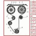
Figure: 53. Gearbox drive of the check point Maz-5551, 5549, Maz-5335, 5336, 5337
1 - gear shift lever; 2 - lever of the switching mechanism; 3 - a roller of gear shifting; 4 - crankcase of the remote gear shifting mechanism; 5 - intermediate gear shift lever; 6 - finger; 7 - hinge earring; 8 - rod tip; 9 - tie bolts; 10 - thrust; 11 - intermediate mechanism; 12 - locking bolt; 13 - transverse roller.
When touching the handle of the lever 1 of the instrument panel or the cab cover, carry out the following adjustment:
Set lever 1 to neutral position;
Disconnect the rod end 10 from the shackle 7 and make sure that the lever 2 is in the neutral position. The fork should be upright and there should be resistance to rotation when swinging angularly;
Fix the transverse roller 13 of the intermediate control mechanism with the locking bolt 12, screwing it all the way into the tapered hole on the roller;
Using the tip 8, having previously loosened the tie bolts 9, adjust the rod 10 in length so that the pin 6 enters the hole of the fork of the tip 8 and the shackle 7 freely, without additional movements to align the holes, and connect the tip with the shackle, tighten the tie bolts of the tip;
Loosen the locking bolt 12 five turns and lock with a nut.
Repair of the gearbox of the gearbox Maz-5551, 5549, Maz-5335, 5336, 5337
Determination of the cause and elimination of a malfunction in the gearbox of the Maz-5551, 5549, Maz-5335, 5336, 5337 gearbox rarely necessitate its complete disassembly.
In some cases, to eliminate the malfunction, you can limit yourself to removing the gearbox cover, for which first remove the remote control mechanism for the gearbox.
If it is necessary to replace or repair parts located in the gearbox housing, it must be removed from the vehicle.
To do this, first of all, drain the oil from the gearbox, disconnect it from it cardan shaft, disconnect the shift drive rod from the shift mechanism cover and the clutch drive rod from the clutch lever and remove the bracket for the additional gearbox support.
Having brought the lifting trolley under the gearbox housing Maz-5551, 5549, Maz-5335, 5336, 5337, tighten the box, unscrew the bolts securing the box to the engine, disconnect the drive shaft end of the box, lower the box onto the cart.
In the future, to eliminate any malfunction or replace individual parts, it is sufficient to disassemble the gearbox into separate units.
Disassembly of the Maz-5551, 5549, Maz-5335, 5336, 5337 gearbox begins with the removal of the remote shift mechanism and the upper gearbox cover.
In doing so, care must be taken not to damage the gaskets.
Remove the clutch release clutch from the drive shaft bearing cover, having previously disconnected the clutch lubrication hose and return springs from the fork.
The shaft of the clutch release fork is removed, after having unscrewed the tie bolt and turned the shaft 180 °. In this case, you can use a soft drift.
Using a universal puller, remove the flange from the driven shaft of the Maz-5551, 5549, Maz-5335, 5336, 5337 gearbox and puller bolts, the cover from the drive shaft assembly with an oil seal and a gasket.
Striking the drive shaft with an aluminum hammer and shaking it by hand, the drive shaft assembly with the bearing is removed. To remove the driven shaft from the crankcase, you must first remove the cover rear bearing and using a puller, press out the rear bearing of the driven shaft, having previously removed the retaining ring from it.
The driven shaft of the gearbox Maz-5551, 5549, Maz-5335, 5336, 5337, assembled with gears, is removed from the box crankcase using wire grips, removing the 1st gear gear from the splines and reverse.
The intermediate shaft is removed in the same way after removing the rear bearing cover intermediate shaft, thrust washer and rear bearing of the intermediate shaft.
Then they are removed from the gearbox housing of the gearbox Maz-5551, 5549, Maz-5335, 5336, 5337 oil pump and gasket.
To remove a gear block with bearings and an intermediate sleeve from the crankcase, you must first press out the reverse gear block axle from the crankcase using a puller.
The need for further disassembly of the gearbox is determined by visual inspection.
Dismantling the drive shaft is straightforward, since after removing the bearing ring nut, the bearing is pressed together using a puller.
When disassembling the slave and intermediate shaft Gearbox Maz-5551, 5549, Maz-5335, 5336, 5337, it is necessary first of all to press the bearings using universal pullers and remove the locking spring rings of bearings and gears with special pullers.
For further disassembly of the driven shaft, remove the IV and V gear synchronizers. To remove the V gear from the shaft, remove the key from the groove on the shaft.
Then, having turned one slot, using a screwdriver, remove the thrust washer of the V gear gear.
Under the press from the driven shaft of the gearbox Maz-5551, 5549, Maz-5335, 5336, 5337 through a mandrel and a wooden gasket, the bushings of gears and synchronizers are pressed, the gears and synchronizers II and II are removed III gear.
The final disassembly of the intermediate shaft after removing the bearings and locking rings is also carried out under a press or using a universal puller.
First of all, the gear wheel of the intermediate shaft drive is pressed, then the gears of the V and III gears, the spacer sleeve is removed, and finally the gear of the II gear is pressed.
Dismantling the gearbox cover Maz-5551, 5549, Maz-5335, 5336, 5337 with a gearshift mechanism, as well as the gearbox oil pump, usually does not cause any particular difficulties.
After disassembling the gearbox assembly, rinse the parts in kerosene or diesel fuel and blow off with compressed air.
An external examination reveals cracks, breakages, thread breakdowns, chipping and breakage of gear teeth and other damage.
If there are cracks or broken teeth, as well as increased wear of the teeth, the gears are replaced.
In the case of a synchronizer, loosening of the seating of the clutch pins on the carriage, wear of the tapered rings, wear of the teeth of the carriages and wear of the spline holes are possible.
When the coupling on the synchronizer carriage of the Maz-5551, 5549, Maz-5335, 5336, 5337 gearbox is loosened, the unusable pins are drilled out and new ones with brass welding are installed instead. The welding place is cleaned.
When determining the degree of wear of the bronze conical rings of the synchronizer clips, use the conical surfaces of the corresponding gears mating with it.
When the ring is put on the gear, the gap between the end of the tooth and the gearbox synchronizer holder Maz-5551, 5549, Maz-5335, 5336, 5337 is measured.
The wear of the tapered ring is considered within the permissible range if the gap between the end of the tooth and the holder is at least 1.5 mm.
The wear of the teeth of the carriages (along the length) from the inclusion side is allowed up to 8 mm.
Welding of cracks in the synchronizer yoke is not allowed.
The assembly of units, as well as the final assembly of the Maz-5551, 5549, Maz-5335, 5336, 5337 gearbox are performed in the reverse order.
In this case, the parts of one set should be used as much as possible.
This is especially important for gears from noiseless operation conditions.
However, when rejecting one of the mating parts, it is necessary to select the most tight fit in such mates as spline landings of synchronizer carriages, gears of 1st gear and reverse gear, landing of bearings on shafts and in crankcase sockets and other joints, while observing the conditions for smooth movement on spline shafts , uniform rotation of shafts and gears without jerking and jamming, etc.; when replacing the synchronizer or drive shaft, as well as one of the gears of the driven shaft (except for the 1st gear and reverse gear), grind the tapered surfaces of the synchronizers to the tapered surfaces of the gear or drive shaft.
The area of \u200b\u200bthe contact marks of each tapered surface should be at least 65% of the total area and be evenly distributed over the entire tapered surface.
After assembly, all gearbox shafts of the Maz-5551, 5549, Maz-5335, 5336, 5337 gearbox should rotate easily and smoothly.
The gearbox is installed on the vehicle in reverse order.
After installing the box, check the clarity of all gear shifting.
Maintenance of the gearbox of the gearbox Maz-5551, 5549, Maz-5335, 5336, 5337
Maintenance of the gearbox of the Maz-5551, 5549, Maz-5335, 5336, 5337 gearbox consists in periodically checking the oil level and changing it in the crankcase in accordance with the instructions in the lubrication chart.
Oil is poured into the gearbox housing up to the level of the control plug.
The oil should be drained while hot through both drain holes.
There is a baffle in the oil pan, so it is impossible to pour out all the oil through one hole.
After draining the oil, remove the cover in the lower part of the Maz-5551, 5549, Maz-5335, 5336, 5337 gearbox housing, in which the oil-receiver of the oil pump with a magnet is placed, rinse them thoroughly and reinstall.
In this case, you should pay attention not to block the oil line with a cap or its gasket.
When the gearbox control lever is in the neutral position, the engine is started for 7-8 minutes, then it is stopped, the spindle oil is drained and the gearbox is filled with the oil provided by the lubrication card.
Since the Maz-5551, 5549, Maz-5335, 5336, 5337 gearbox has an oil pump, it is strictly forbidden to flush the gearbox with kerosene or diesel fuel, because insufficient vacuum at the suction can lead to its failure.
Remember that the oil pump is driven by the intermediate shaft of the gearbox.
Therefore, when the engine is not running, the oil pump does not supply lubricant to the gear bearings of the driven shaft and to the tapered surfaces of the synchronizers.
This is especially important to know when towing a Maz-5551, 5549, Maz-5335, 5336, 5337 car with an idle engine.
If the engine is being towed, it is necessary to disengage the clutch and engage the IV (direct) gear in the box or disconnect the latter from the transmission, otherwise scuffing of the sliding surfaces and wear of the synchronizer rings are possible.
It is also necessary to check the reliability of fastening the top cover to the gearbox housing and the control mechanism to the top cover.

Spare parts for trucks Ural, Kraz, MAZ, Kamaz. Engine parts YaMZ-236, YaMZ-238
___________________________________________________________________________
Control drive of the YaMZ gearbox of Maz-5516, Maz-5440 cars
The gearbox drive of Maz-5516, Maz-5440, 64229, Maz-54323, 54329 and YaMZ - 239 cars is shown in Figure 4. During operation, if necessary, the following gearbox drive adjustments are made:
The procedure for adjusting the control of the YaMZ-239 checkpoint for Maz-5516, Maz-5440, 64229, Maz-54323, 54329 vehicles is as follows:
Set lever 2 to neutral position;
By longitudinal movement of the plate 16 with the bolts 17 released, set the angle a of the lever 1;
By changing the length of the rod 3 set the angle.
If the travel of the plate 16 or the adjustment range of the thrust 3 is insufficient, loosen the bolts 5, move or rotate the thrust 6 relative to the shank 4, tighten the bolts 5 and repeat the adjustment of the angles a, b as described above.
Angle a should be 80 °, angle b 90 °.
Adjustment of the locking device of the telescopic elements of the YaMZ-239 gearbox of Maz-5516, Maz-5440, 64229, Maz-54323, 54329 vehicles with the raised cab as follows:
Unpin pin 8 and disconnect the rod 6 from the fork 9 of the gearbox drive lever;
Push the inner rod 6 up to the stop of the projections of the earring 12 into the grooves of the tip 15;
Keeping the mechanism compressed, screw in the shank until the mechanism is locked by the sleeve K) under the influence of spring 11:
Tighten the lock nut 13, check the accuracy of the locking mechanism. When the mechanism is locked, the axial and angular backlash should be minimal.
In the unlocked position, the sleeve 10 is shifted to the left. The movement of the extension should be smooth, without jamming, and the locking mechanism should ensure that the extension rod is firmly locked in its original position.
When connecting rod 6 to fork 9, the hole in the shackle for pin 8 must be located above the longitudinal axis of rod 6. Adjust the drive with the engine off.
When the cab is lifted, oil under pressure from the cab lift pump is supplied through the hose 7 to the cylinder of the locking device and the mechanism 6 is unlocked.
After lowering the cab, to securely fix the telescopic mechanism 6 in the locked position, it is necessary to move the gear lever 1 forward in the direction of the vehicle in a movement similar to engaging a gear. In this case, the mechanism is blocked and is subsequently ready for operation.
Scheme of gear shifting of the check point of cars Maz-5516, Maz-5440, 64229, Maz-54323, 54329 and YaMZ-239, see Figure 5.

Fig. 4. Gearbox control drive YaMZ cars Maz-5516, 64229, Maz-54323, 54329
1 - lever; 2 - lever; 3.4 - thrust; 5.17 - bolt; 6 - thrust (telescopic mechanism); 7 - hose; 8 - finger; 9 - plug; 10 - bushing; 11 - spring; 12 - earring; 13 - lock nut; 14 - shank; 15 - tip; 16 - plate; 18 - switch
Gearbox control drive for cars Maz-5516, Maz-5440, 64229, Maz-54323, 54329 with MAN engine
When controlling the gearbox of cars Maz-5516, Maz-5440, 64229, Maz-54323, 54329, be guided by the following:
The main gearbox and the demultiplier are controlled using the gearbox lever according to the diagram shown in Figure 19 (gearbox ZF).
The transition from the slow range of the range to the fast is carried out by moving the lever in the neutral position away from you, overcoming the force of the retainer, from the fast range to the slow - in the reverse order.
The divider is controlled by a flag on the gear lever handle. The transition from slow range (L) to fast (S) and vice versa is carried out by pressing the clutch pedal all the way after the flag is moved to the appropriate position. Switching is possible without switching off the transmission in the main gearbox.
Adjustment of the gearbox control drive of the gearbox of cars Maz-5516, Maz-5440, 64229, Maz-54323, 54329
During operation, if necessary, the following adjustments are made to the gearbox drive of Maz-5516, Maz-5440, 64229, Maz-54323, 54329 cars for MAN engines:
Adjusting the position of the lever in the longitudinal direction;
Adjusting the position of the lever in the transverse direction;
Adjustment of the locking device of the telescopic drive elements.
Adjustment of the position of the lever 1 (Figure 7) in the longitudinal and transverse directions is carried out by moving and rotating the rod 5 in the shank 6 with the bolts 7 released.
In this case, the angle a should be 85 °, the angle e \u003d 90 °. The angle a can also be adjusted by moving the plate 3 with the bolts 2 released.

Fig. 5. Scheme of gear shifting of the check point of cars Maz-5516, Maz-5440, 64229, Maz-54323, 54329, YaMZ-239
M - slow range; B - fast range.

Fig. 6. Scheme of gear shifting of the gearbox ZF of cars Maz-5516, Maz-5440, 64229, Maz-54323, 54329
L - slow range; S - fast range.

Fig. 7. Gearbox control drive for cars Maz-5516, Maz-64229, Maz-54323, 54329
1 - lever; 2, 7 - bolt; 3 - plate; 4 - hose; 5 - intermediate mechanism; 6 - shank; 8 - growl
The gearbox drive of Maz-5440 vehicles is shown in Figure 8.
The main box is switched by lever 1 of the remote control mechanism. The additional box is controlled by the range switch 18 located on the gear shift lever 1.
The lower position of the range switch turns on the fast range in the additional box, with the upper position the slow range.
During operation, if necessary, the following adjustments are made to the gearbox of Maz-5440 vehicles:
Adjustment of the angle of inclination of the lever 1 in the longitudinal direction;
Adjustment of the angle of inclination of the lever 1 in the transverse direction;
Adjusting the telescopic locking device. To adjust the angle of inclination of the lever in the longitudinal direction:
Set lever 2 to the neutral position by tightening the neutral position lock on the shift mechanism 20 (for the YaMZ gearbox - 238M).
Check the neutral position of the gearbox of the gearbox of Maz-5440 cars by moving the roller of the lever 2 in the axial direction by pressing it by hand. In this case, the roller should move by an amount of 30 - 35 mm;
Loosen the tightening of the bolts 17 and by longitudinal movement of the plate 16 set the angle "a" to 90 degrees;
In case of insufficient travel of the plate 16, loosen the bolts 5, move the rod 6 relative to the shank 4, tighten the bolts 5 and repeat the adjustment of the angle "a" by moving the plate 16.
Adjustment of the lever 1 in the transverse direction is carried out by changing the length of the lateral rod 3 by disconnecting one of the tips with unscrewing the nut of its fastening, followed by adjusting the length so that the lever 1 takes a vertical position.
After adjustment, return the neutral position lock to its original position (for the YaMZ-238M gearbox).
Adjustment of the locking device of the telescopic gearbox of the Maz-5440 vehicles should be done as follows:
Unpin the pin, unscrew the nut, remove the pin and disconnect the rod 6 from the fork 9 of the gear lever;
Loosen the lock nut 13 and unscrew the shank 14 until the thread stops;
Push the inner rod 6 up to the stop of the earring projections into the grooves of the tip 15;
Holding the mechanism in a compressed state, screw in the shank 14 until the mechanism is locked by the sleeve 10 under the influence of the spring 11;
Tighten the lock nut 13, check the accuracy of the locking mechanism. When the mechanism is locked, axial and angular play should be minimal. In the unlocked position (bushing 10 is displaced to the right), the internal link must be pushed out by the return spring by 35-50 mm.
Further movement of the extension rod should be smooth, without jamming and the locking mechanism should ensure that the rod extension is clearly fixed in its original position.
Avoid bending or bending of the drive rod and its telescopic components. Adjust the gearbox drive with the engine off.

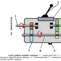
Fig. 8. Gearbox control drive for Maz-5440 cars
1,2 - lever; 3, 4, 6 - thrust; 5, 7, 17 - bolt; 8 - finger; 10 - bushing; 11 - spring; 12 - earring; 13 - nut; 14 - shank; 15 - tip; 16 - plate; 18 - switch 19 - ball; 20 - switching mechanisms.