Disassembly and assembly of the intermediate shaft photo, Gearbox device Niva 2121, Niva 2131
Service and operation of the Niva 2121 box. Instructions for the repair of the cardan, axle and wheel drive Niva 2131.Disassembly and assembly of the intermediate shaft Niva 2121, VAZ 2131, Lada 4x4
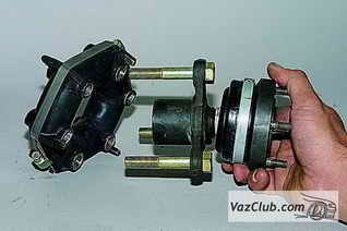
We disassemble the intermediate shaft of the VAZ 2121 to replace the elastic (rubber) coupling or hinge of equal angular velocities.
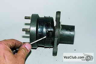
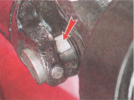
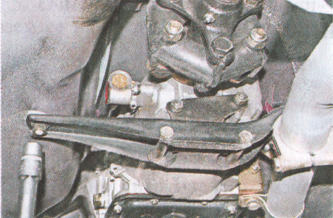
We mark the location of the coupling relative to the flange, ...
... as well as the number and position of the balancing washers in relation to the coupling.
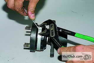
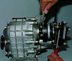
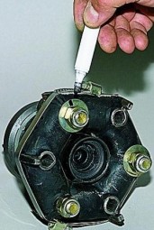
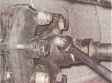
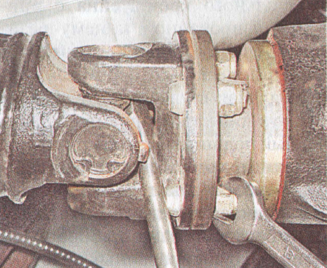
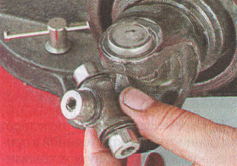
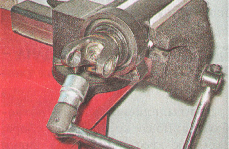
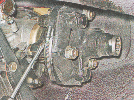
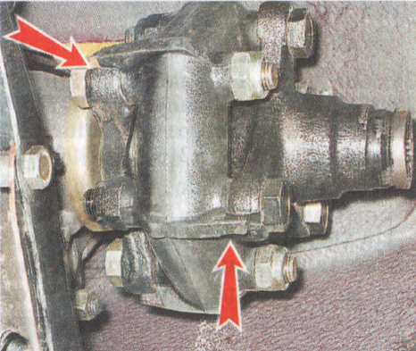
 Keeping the bolts from turning with a 19 key, turn off three nuts with a head of the same dimension.
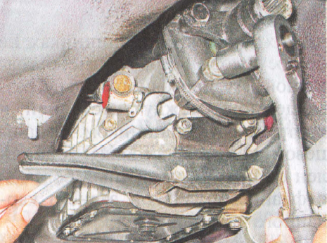
 Disconnect the coupling and flange.
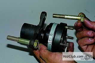 Turning the hinge, remove the bolts from the flange holes elastic coupling vaz 2131.
 Prying with a screwdriver, take out the plastic plug.
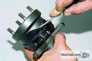
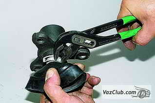
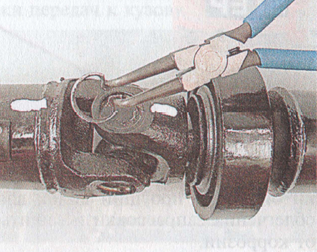
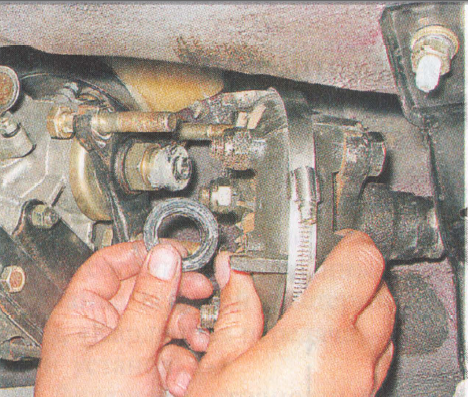
 Squeezing the clamp with sliding pliers, remove it.
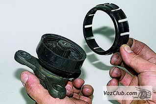
 Move the plastic cover with a screwdriver ...
 … And remove the rubber protective cover from the constant velocity joint housing.
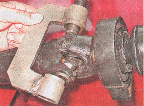
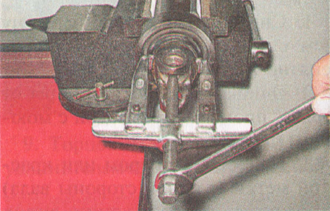
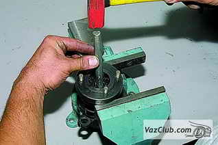 We place the body of the Niva 2131 hinge on the open jaws of the vise and, striking through a soft metal drift at the end of the flange of the elastic coupling, knock out the flange.
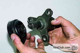
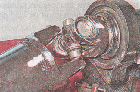
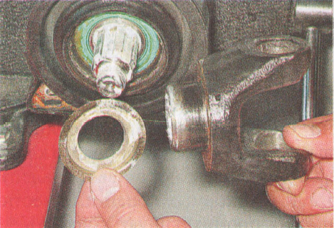
 Disconnect the hinge and flange.
 We pull off the plastic casing from the rubber boot.
Pulling back rubber cover,…
 … Squeeze the clamp with sliding pliers and remove it.
 Remove the rubber protective cover.
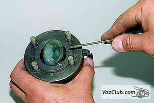
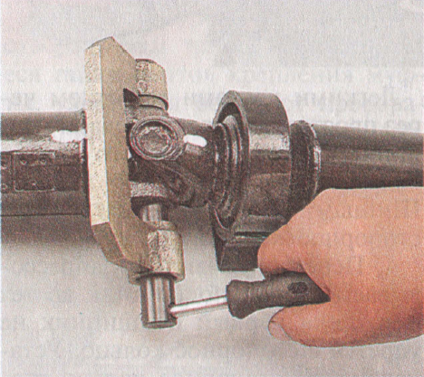
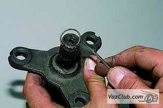 Prying off with a screwdriver, remove the hinge retaining ring.
Dismantling and assessing the condition of the joint parts are similar to the corresponding operations described in the chapter Front wheel drives.
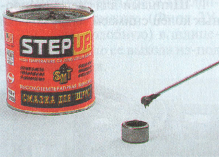
We collect intermediate shaft niva 2121 in reverse order. We put 20 cm3 of SHRUS-4 grease into the moved or new hinge. Before connecting the hinge to the flange of the elastic coupling, install a small clamp of rubber protective cover.
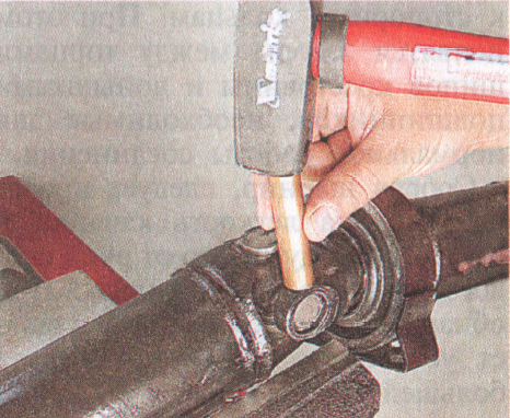
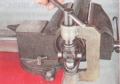
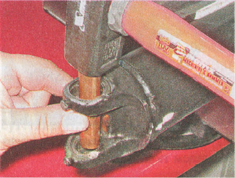
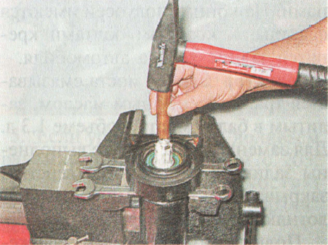
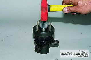 We press the hinge onto the flange, striking through the pipe section along the hinge holder.
 Before installing the rubber sleeve, we squeeze it with a clamp.
We place the used coupling according to the marks relative to the flange. We place the old balancing washers according to the marks relative to the VAZ 2121 coupling. When installing a new coupling, it may be necessary to balance the shaft assembly.
|
Box device Gearbox device Niva 2121, Niva 2131 |
|
Changing the oil in the box Oil change in gearbox Niva 2121, Niva 2131 |
|
Gland input shaft Replacing the input shaft oil seal Niva 2121, Niva 2131 |
|
Replacing the output shaft seal Removal and installation of the secondary shaft oil seal Niva 2121, Niva 2131 |
|
Installing and removing the transmission |
Page 1 of 2
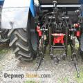
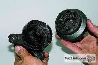
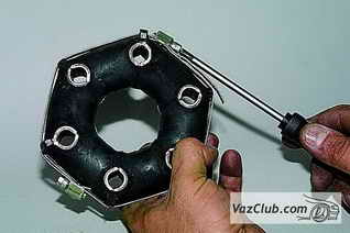
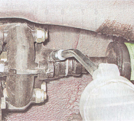
The intermediate shaft transmits the torque from the transmission output shaft to the transfer case drive shaft. It consists of an elastic coupling, a flange and a constant velocity joint. The intermediate shaft is centered on the output shaft of the gearbox with a rubber bushing.
The elastic coupling allows the transmission of torque with slight changes in the angle between the shafts of the gearbox and transfer case, protects transmission parts from dynamic shocks and reduces noise and vibration cardan transmission when working.
| fig. 1 |
The elastic coupling consists of six steel liners connected by rubber bridges. Due to its elasticity, the clutch dampens jerks in the vehicle's transmission. The elastic coupling is attached to the output shaft flange with three bolts passed through the holes in the bushings. The other three holes are used to fasten the coupling to the flange on the intermediate shaft. Balancing washers are located under the bolt nuts. When disassembling, we mark their location, so that later they can be installed in their original places. In order not to disturb the balance, we note the relative position of other parts of the intermediate shaft. A constant velocity hinge is put on the spline end of the flange of the elastic coupling. Its structure is similar to the external drive joint. front wheel... The hinge is secured against displacement by a retaining ring located in the groove on the flange shaft. The hinge is protected from dirt by a rubber bellows cover and a plastic plug in the rear end of the hinge housing. The cover is fixed on the flange shaft and the hinge body with special clamps with locks. There is a protective plastic cover under the large clamp (on the hinge body).
On the first VAZ-2121 models, a cross was installed instead of a hinge of equal angular velocities.
|
Remove the transfer case assembly with intermediate shaft (see Removing the Transfer Case). |
1 |
|
|
|
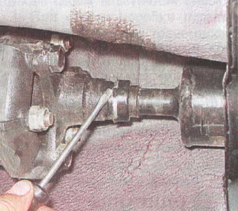
 ... Keeping the shaft from turning with a screwdriver, use the "13" key to unscrew the four nuts securing the intermediate shaft to the transfer case flange.
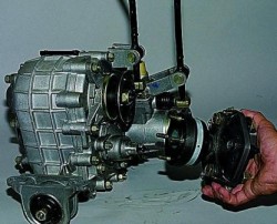 2. Remove the intermediate shaft. Install the intermediate shaft on the transfer case in reverse order.
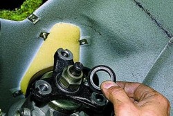 3. Before installing the intermediate shaft assembly with
 Dismantling the intermediate shaft
Disassemble the intermediate shaft to replace the elastic (rubber) coupling or constant velocity joint.
|
|
|
|
|
|
 1. Note the location of the coupling relative to the flange, as well as the number and location of balancing washers relative to the coupling.
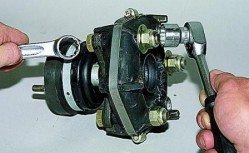 2. Keeping the bolts from turning with a 19 key, unscrew three nuts with a head of the same dimension.
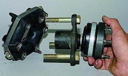 3. Disconnect the coupling and flange.
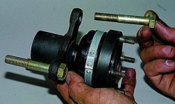 4. Turning the hinge, remove the bolts from the holes in the flexible coupling flange.
Symptoms: knocks when starting off the car, vibrations transmitted to the body when the car is moving, knocks when changing gears.
Possible reason: parts of the driveline are faulty.
Tools: a set of wrenches, a set of screwdrivers, a hammer, a jack, supports for the body, a piece of pipe (outer diameter - 22 millimeters, inner - at least 15 millimeters, length - 10 millimeters), pliers for circlips, puller for driveshaft bearings, universal two-grip stripper, center punch, fine beard.
Note.This manual contains information on checking, removing and repairing the cardan transmission, describing the most complete range of work to eliminate possible malfunctions... For convenience, the instruction is divided into logically separated subsections (A, B, C, D).
A. To check the driveline, follow the steps below:
1. Place the car on an overpass or inspection pit.
2. Clean the outer surfaces of the driveline parts from dirt.
3. Make sure all available threaded connections cardan gears are tightened with the necessary force.
4. Use a large screwdriver to rock the forks cardan joint relative to each other, making sure that there is no or no play in the bearings. If a backlash has been identified, then the bearings together with the cross must be replaced.
5. Fix the front cardan shaft from rotation and at the same time rock the elastic coupling. Make sure there is no or no corner play in the splined joint.
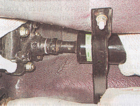
6. Inspect the elastic coupling and intermediate bearing of the front cardan shaft... If rubber delamination from the metal base, cracks and ruptures are detected, the coupling and (or) intermediate support must be replaced.
7. The splined joint of the propeller shaft requires periodic lubrication. To do this, unscrew the plug using the key "11" and install a grease fitting in its place.
8. Using a medical syringe, pump lubricant into the spline through a grease fitting until it exits the flange gland.
9. Unscrew the grease nipple and replace the plug.
10. If any defects were removed during the inspection, carry out a test drive. In the event that the malfunctions have not been eliminated, follow the instructions below.
B. To remove the driveline, follow the steps below:
10. Place the vehicle on an overpass or inspection pit. Install wheel chocks under the front wheels. Make sure the gear lever is in neutral.
11. Hang up the rear wheels.
12. Using paint or a center punch, mark the relative position of the universal joint flange yoke and the main drive pinion flange.
13. Using a 13 ”open-end wrench, unscrew the four self-locking nuts, while simultaneously securing the propeller shaft from turning using a large screwdriver or other tool that can act as a lever. If you find rust on the threaded parts of the bolts, "soak" these connections with a lightly penetrating lubricant... Then use an open-end wrench "13" with wide jaws (usually such a wrench can be found in a set of tools for adjusting the clearances in the valve drive). If, when unscrewing the nuts, the bolts will turn, press their heads against the flange, applying force through a screwdriver.
14. Remove the bolts from the holes and then separate the flanges while moving the driveline forward. In case these flanges have been "glued" with rust, try hitting the flange fork with a few hammer blows.
Note. When "sticking" the flanges, be extremely careful not to damage the parts.
15. Suspend the rear propeller shaft by tying it to the joint to the upper reaction rods rear axle so that the shaft does not come into contact with the parking brake drive cables.
16. Using a flathead screwdriver, unbend the four tabs securing the front propeller shaft seal ring.
17. Move the clip to the right over the end of the propeller shaft.
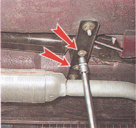
18. Using a 13 ”socket wrench with an extension, unscrew the two bolts securing the intermediate support to the cross member.
19. Disconnect the splined joint of the propeller shaft and the flange of the elastic coupling, and then remove the propeller drive from the car towards the rear axle, having previously untied it.
B. To disassemble and assemble the driveline, follow these steps:
20. Clean the joints and shafts from dirt with a brush, and then wash the parts with water and detergent.
21. Mark the relative position of the universal joint forks (with a center punch or paint). This is necessary to keep the driveline balanced.
Note. The following describes the disassembly and assembly of the universal joint. On cars with high mileage Before performing this cycle of operations, it is recommended to first tap the end surfaces of the circlip through a suitable metal drift, and then apply a layer of easily penetrating grease to them.
22. Using a snap ring pliers, remove the four rings.
Note. The bearings are fitted in the forks with an interference fit, and corrosion further increases this interference fit. In this case, it is recommended to use not a hammer, but a puller, in addition, it is necessary to treat the entire hinge with a readily penetrating lubricant. These measures are necessary in order not to damage the parts.
23. Using a bearing puller, do not completely press out the bearing into the bowl of the device until the cross rests on the fork. In the process of performing this operation, pay attention to the height of the part of the extraction of the part (this value should be approximately one third of the entire height of the bearing).
24. Fix the propeller shaft by the yoke in a vise so as not to damage the pipe. After that, using a hammer, apply a few blows through a drift made of soft metal on the eyes of the front propeller shaft fork, thereby displacing the universal drive shaft until it stops in the fork. During this operation, the bearing must be partially pressed out.
25. Make two half rings from the pipe section prepared earlier.
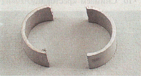
26. Move the fork of the front propeller shaft together with the cross in the opposite direction, and then install the two manufactured half rings on the cross spike (only one half ring is visible in the attached photo).
27. Using a puller, press out the bearing.
28. Remove the cross from the holes in the fork of the rear propeller shaft.
29. In the same way, press the bearing out of the front propeller shaft, holding the latter in a vice. The shaft must be clamped so as not to deform the pipe.
30. Dismantle the crosspiece.
31. Press out the bearings from the forks of the rear and front cardan shafts, for which purpose strike with a hammer through a drift made of soft metal.
Note. Before proceeding with the assembly of the universal joint, additionally clean the parts from dirt.
When installing, it is necessary to provide the cross with an axial clearance of 0.01 to 0.04 millimeters. With a larger clearance, the bearing seals become leaking, and the balance of the cardan drive is also disturbed. The required clearance can be achieved by installing circlips of suitable thickness. Retaining rings for spare parts are supplied with a thickness of 1.50-1.62 mm.
Note. The crosspiece and bearings must never be replaced separately.
32. Before installing new bearings and spider, make sure that these elements are clean, then coat the needle rollers with a generous amount of lubricant. Also, it is necessary to fill with lubricant the holes located in the spikes of the cross.
33. Apply a thin layer of lubricant to the inner surfaces of the fork eye holes. This is to make it easier to press in and protect the connection from corrosion.
34. Install O-rings on the spikes of the universal joint (the bifurcated edge must face the bearing), and also install the plastic end washers in the holes located in the spikes.
35. Place the transmission cross between the fork lugs. After that, applying light blows with a hammer through a soft metal spacer, press the bearing into the fork a little deeper than the groove for the circlip. Using pliers, install the circlip into this groove.
36. Turn the fork over and then press in the second bearing until the first bearing rests against the circlip. Install the second bearing retaining ring.
37. Using the same method, press in the bearings of the second fork eyelet.
38. After all bearings are pressed in and all circlips are installed, tap the forks with light blows with a hammer. This measure is necessary to ensure that the bearings are firmly pressed against the circlip. After that, gaps should appear between the end surfaces of the spikes of the cross and the bottoms of the bearings, which are necessary for the normal mobility of this connection.
39. Check for ease of rolling, as well as absence of axial play in the forks. In the event that backlash has been detected, it is necessary to install retaining rings with a large thickness.
Note. The following describes the removal and installation of the intermediate support. Most often, the intermediate bearing needs to be removed if its bearing is worn or damaged to replace it. However, the most reasonable solution is to replace the intermediate support assembly.
40. Clamp the front propeller shaft in a vice so as not to damage the pipe.
41. Using a thin bit, loosen the nut holding the front universal joint fork.
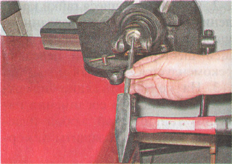
42. Using a 27 ”socket wrench, unscrew the nut that secures the front universal joint yoke.
43. Using a universal two-grip extractor, press the fork off the propeller shaft splines.
44. Remove the fork with an oil deflector from the propeller shaft.
45. Knock the propeller shaft out of the bearing by placing the intermediate support on two suitable wrenches, and then hit it several times with a hammer through a soft metal drift.
46. \u200b\u200bRemove the second dirt deflector from the shaft.
47. Install the new intermediate support in reverse order. Take measures to protect the splines of the front propeller shaft against corrosion by applying any grease to them.
48. Replace the front propeller shaft yoke fixing nut with a new one and tighten it to 79.4–98.0 N ∙ m. After tightening, lock the nut with a bit.
Note. The following describes the removal and installation of the flexible coupling. The flexible universal joint coupling most often requires dismantling to replace its element made of rubber. In the event that this element is not damaged and will be re-installed, it is required to purchase a worm clamp, the diameter of which will be at least 140 millimeters. This clamp is required to tighten the coupling during installation. As a rule, a special mounting clamp is included with a new coupling.
49. Using a 13 ”socket wrench with an extension, unscrew the two nuts securing the gearbox cross member to the car body.
50. In order to facilitate dismantling and subsequent installation (when using the old coupling), pull off its rubber part using the clamp mentioned earlier.
51. Using a 19 ”socket wrench, unscrew the three self-locking nuts of the bolts securing the elastic coupling of the cardan drive. In the process of unscrewing the nuts, secure the bolt heads from turning with a second wrench of the same size.
52. Dismantle the coupling with the centering ring and rubber gasket.
53. Unscrew the three nuts of the bolts securing the flexible coupling to the front propeller shaft flange, and then separate the parts.
54. Mount the new flexible joint of the universal joint in reverse order. During the installation process, be sure to make sure that the protrusions made on the clutch fit into the corresponding grooves made on the flanges of the front propeller shaft and the gearbox output shaft.
D. To install the driveline, follow these steps:
55. Clean the splined surfaces of the flexible coupling flange and propeller shaft, and then lubricate the splines with lubricant. After the flange-to-shaft connection is assembled, reinstall the gland yoke and then bend the retaining tabs.
56. Replace with new self-locking nuts securing the flange yoke to the final drive pinion flange.
57. Apply a thin coat of any grease to the contact surface of the flange joint. This is to protect the connection from corrosion.
58. Install the cardan transmission in reverse order, aligning the marks on the flanges during disassembly.