The topic about what bridges are better for UAZ for sure more than once. Someone for civilians who are for military bridges on UAZ. Let's try to figure out something. Of course, Weazbuk to help us. There is enough information there. You can collect a small collage 🙂
Civil bridges on UAZ
Device of UAZ bridges.
Two types of leading bridges are used on the UAZ cars: leading bridges with single-stage main transmission - are installed on cargo-passenger cars UAZ-31512 and cars of the Wagon layout UAZ-3741, UAZ-3303, UAZ-3962 N UAZ-2206; P-shaped leading bridges with on-board transmission - installed on cargo-passenger cars UAZ-3151.
Installation of P-shaped leading bridges (Complete front and rear) on UAZ-31512 cars are possible with simultaneous installation. cardan shafts Car UAZ-3151. The installation of P-shaped bridges with onboard transmission to the car of the car layout car requires significant refinement of the bridge design, bustle, busty thrust, car suspension, manufacture of cardan shafts shortened by 10 mm, and cannot be performed outside the factory (without its recommendations).
Lead bridges with single-stage main transmission. The middle part of the front and rear axles has the same device (Fig. 1). 
Fig. 1 Rear Axle UAZ Scheme
1 - Safety valve; 2 - Differential bearing; 3 - adjusting gaskets; four - rear Bearing leading gear (single row roes); 5 - adjusting ring; 6 - oil tongue ring; 7 - nut; 8 - package of adjustment pads; 9 - leading gear; 10 - front bearing leading gear (roller conical double-row); 11 - Stubborn washer; 12 - driven gear;
Carter - cast detachable in the vertical plane. In both half of the crankcase, the casing of the semi-axes is pressed and additionally fastened with electrodes. The leading gear of the main transmission is set on two bearings by konichkom roller bearing 10, located in the neck of the crankcase, and the cylindrical roller 4, located in the bilter of the crankcase. Between the end of the outer ring of a dual electrical bearing and the crankcase, an adjusting ring 5 positions of the lead gear is installed. A dual conical bearing is regulated by a package of 8 pads. The driven gear is attached to the flange of satellite boxes with special bolts. Differential conical with four satellites. The satellite box is detachable, consists of two halves connected by bolts. The sections of the differential semi-axes have replaceable stubborn washers 11. The differential is installed on two conical roller bearings 2, adjusting gaskets are installed between the ends of the satellite box and the internal rings of the differential bearings. Between the flange of the lead gear and the dual conical bearing installed an oil tongue ring 6.
On the left axes of the semi-axes are safety valves 1, preventing increase in pressure in bridge cranks.
To the external ends of the housings of the rear axles of the rear axles are welded with butt welding pin with flanges for mounting brake shields (Fig. 2).

Fig. 2 rear wheel hubs.
1 - brake drum;
2 - wheels disc;
3 - cuffs;
4 - lock washer;
5 - counter nut;
6 - half a half
7 - pin;
8 - gasket;
9 - Bearing;
10 - hub;
Wheel hubs The front and rear axles are the same (see Fig. 2). On UAZ-31512 and UAZ-3151, the hubs of the wheels are non-violent. Bearings and details of their attachments are interchangeable. On cars of the car layout, the hubs of the UAZ-31512 car are installed. Each hub is installed on two identical conical bearings 9. The outer rings of bearings are pressed into the hub and from the axial movements are held by stubborn rings. Internal bearing rings are installed on the pin freely. Bearings are tightened with two nuts and stop the lock washer 4 installed between the nuts. Between the inner ring of the outer bearing and the nut is installed a stubborn washer with a protrusion included in the groove on the pin.
To prevent the leakage of lubrication from the hub and get into it dust, dirt and water, from the inner end, the reinforced rubber cuffs 3 are installed with springs assembly. Between the cuff and the inner bearing, you install a stubborn washer to prevent damage to the working edge of the cuff when removing the hub.
The outer ends of the shells of the front axles of the front axles end with the flanges to which the bolts are attached ball supports 3 (Fig. 3). 
Fig. 3 Rotary pin front Bridge Car UAZ 31512
1 - turntable arm; 2 - casing of the semi-axis; 3 - rubber cuff in a metal casing; 4 - gaskets; 5 - ball support; 6 - the housing of the rotary pin; 7 - & nbsp; support washer; 8 - Pokworn's lining; 9 - kkvorn; 10 - Maslenka Press; 11 - lock pin; 12 - pin; 13 - wheel hub; 14 - lead flange; 15 - Wheel shutdown coupling; 16 - coupling bolt; 17 - the bulb of the lock; 18 - Protective Cap; 19 - Shkworn's sleeve; 20 - gaskets; 21 - the inner ring of the gland; 22 - Partition Ring; 23 - outer ring; 24 - rubber cuff; 25 - Outdoor sealing felt ring; 26 - Stubborn washers; 27 - adjusting bolt. timing restrictions of the wheel; 28 - focus limitator of the wheel; I - right swivel fist; II - left swivel fist; III - the hub of the front kites are disabled; a - signal groove;
On the ball supports on the pile 9, the housings 6 were installed 6 of the rotary pin, to the ends of which the axes 12 and brake shields are attached to bolts. Inside the ball supports are hinges of equal corner speeds, on the outdoor ends of which devices are installed, allowing you to connect or disconnect the shafts with the front wheels hubs.
"Military" Bridges UAZ
Leading bridges with onboard gears. The middle part of the leading bridges with onboard transmissions differs from the above-described bridges by smaller sizes of differential and the console setting of the main gear gear on two conical roller bearings 5 \u200b\u200band 7 (Fig. 4). 
Fig. 4 Rear Axle of the car UAZ-3151
1 - Carter Cover 2 - Differential Bearing 3, 13 and 49 - Adjustment Gaskets 4 and 23 - Sealing gaskets; 5 and 7 Bearings of the drive gear, 6 - adjusting ring, 8 and 42 - cuffs, 9 - flange. 10 - Nut, 11 - Meszotratel. 12 - support washer, 14 - spacer sleeve, 15 - adjusting ring position of the drive gear, 16 - leading gear, 17 - satellite, 18 and 57 - semi-axes; 19 - on-board cards; 20 and 29 - oil removers, 21 - Ball bearing, 22 and 26 - retaining rings, 24 - Capanta Capanta Case, 25 - Po Face Bearing, 27 - Brake Shield, 28 - Brake Drum, 30 - Wheel Mount Bolt, 31 - Tsazp , 32 - Bearing hubs, 33 - Gasket, 34 - Retained washer, 35 - Leading flange, 36 - Nut and knitting hub bearings, 37 - Stubborn bearing washer, 38 - sleeve; 39 - the slave shaft of the onboard transfer, 40 - resistant rings of bearings, 41 - gaskets; 43 - Bearing of the slave shaft, 44 - driven gear gear, 45 - Slave bearing fastening nut, 46 and 50 - plug plugs, 47 - leading gear gear, 48 and 56 - Satellite boxes, 51 - Carter, 52 - washer Semi-axis gears, 53 - gear semi-axes, 54 - Satellite axis, 55 - driven gear gear
Between the end of the drive gear and the inner ring of the large bearing, an adjusting ring 15 of the drive gear, and between the internal bearing rings is installed spacer sleeve 14, the adjusting ring 6 and adjusting gaskets 13. The drive gear bearings are tightened with a nut 10 fastening nut 10.
Onboard transfers of the rear leading bridge Arranged in crankcasers, which are pressed on the outer ends of the semi-axes of the semi-axes and are fixed with electrodes. The drive gear 47 is installed on the slotone end of the semi-axis 48 between the ball 21 and roller 25 bearings. The ball bearing is fixed by a retaining ring 22 in an onboard transmission crankcase. Between the crankcase and the ball bearing there is an oil reproducer 20. The roller bearing is installed in a removable case, which is attached to the Carter's ribli with two bolts. The internal ring of the roller bearing is fixed on the semi-axis retaining ring 26.
The driven gear 44 gear is centered on the slaughter of the slave 39 and is attached to its flange bolts. The slave shaft relies on the sleeve 38 and the roller bearing 43, which is fixed on the shaft of the nut 45, uncovered after the tightening in the shaft groove. The led shafts of right side gears and nuts fastening bearings have left threads. To distinguish the nut with left-hand threads have a ring groove, and the slave shafts are a deaf hole dia. 3 mm in the end of the shaft. With the wheel hubs, the slave trees of the back side gears are connected by the slotted flanges 35.
On-board transfers of the front leading bridge UAZ are located In swivel pin (Figure 5 of the bridge scheme) 
Fig. 5 Rotary Rotary Runs of the Front Bridge of the UAZ-3151
1 - rubber cuff in a metal casing, 2 - ball support, 3 - hinge equal speed of speeds, 4 - pads, 5 - Press oil, 6 - kkivorn, 7 - Pokworn's lining, 8 - housing of the rotary pin, 9 - Schwerny sleeve, 10 - Ballovy Bearing, 11 - Vedomyi Sideband Shaft, 12 - Hub, 13 - Air Flange, 14 - Coupling, 15 - Spring Fixer Ball, 16 - Protections Cap, 17 - Couplings Bolt, 18 - Tsazf, 19 - Retaining Haika, 20 - Supported washer, 21 - leading gear, 22 - stop pin, 23 - Stubborn washer, 24 - cuff, 25 - support washer, 26 - casing of the semi-axis, 27 - Bolt Restrictions of rotation, 28 - focus-год. - Rotary trough lever, I ... III, and - Same as in Fig. 112.
Carters onboard gears are cast at the same time with the housings of the rotary pin. The drive gear is installed on the slots of the slave of the hinge between the ball and roller strokes and is fixed with the roller bearing with a nut 19, which is sewed into the shaft groove after the tightening. The ball bearing is installed in the core of the Novorotnya pin in the clip with the outer border, which perceive the axial load of the hinge through the bearing. On the external ends of the led front-side gear shafts, devices are installed to connect or disconnect the shafts with the front wheels hubs.
What bridges are installed on different models of UAZ cars?
All cars of the carriage layout ("", "and", "farmers"), on "long goats" (3153 *), as well as the majority of "classical goats" establish the so-called "civil" (they are "ordinary", " Colhomous ") Bridges. On the part of "goats" (models with indexes -03x) establish "military" (they are "gear", "two-stage", "P-shaped") bridges. At the "New Kozlikov" (316 *), the spype bridges are installed with an in-point crankcase. Machines "" (3159 *) and 316 * With an enlarged rollery, "long military" bridges are installed, i.e. gentle with elongated stockings.

Differences of military bridges from civilian.
The military bridge differs from the usual presence of onboard gearboxes. Due to the presence of gearboxes, the bridge is raised relative to the axis of the wheels of 4 cm, which increases the clearance of the machine (the distance from the ground to the lower point of the bridge). The main steam is smaller in size (Carter of the military bridge "hangs" by 4 cm less than civil). The main pair has fewer teeth, and they are larger - it increases the reliability of military bridges compared to civilian. The transfer number of military bridges 5.38 (\u003d 2.77 * 1.94 - gear ratios, respectively, the main and on-board gear) - more "travelers", but less "high-speed" than that of ordinary bridges.
Rear cardan Val. Under military bridges per 1 cm shorter than civilians!

The advantages of military bridges compared with civilians:
- clearance of 30 cm (against 22 cm in civil bridges); According to the latest measurements, the difference of 8 cm is observed only when used on military bridges of rubber I-192. With the same wheels, the difference is only 6 cm. (Winning on gearboxes - 40 mm. Winning on the size of the dief crankcase - 20 mm Total: 60 mm.)
- more "Taigitiousness" (torque) - for the carriage of heavy loads, towing, driving on small mud circulation;
- more reliable due to larger teeth main couple;
- more reliable due to the uniform distribution of the load between the main and onboard gears;
- Designed, including for "accompanying the tank column" and approved the Ministry of Defense of the USSR.
In the military there is a differential of high friction. Those. If you got stuck in the mud with one wheel of the bridge or on the ice, we cost one half and you have one half of the bounce and the second is not (the usual differential works). That this was not invented by military bridges. So on the off-road military bridges are much better.
GP gear ratio (total: GP 2.77 + onboard gearboxes 1.94): 5.38
Road clearance: 300 mm (with tires I-192 215/90 R15 (31 x 8.5 R15)
King: 1453 mm
On the left photo UAZ NA civic bridges and right - UAZ on reducer Bridges — « waries«.
The advantages of civil bridges compared to the military:
- less weight (more comfortable ride and (physically) is easier to repair);
- less details - easier and cheaper repair;
- it is possible to install serial produced self-locking differentials;
- Possible installation of spring suspension (see also Note);
- at the same speed, the engine is less "unlocked" due to a lower gear ratio;
- less noisy (since the onboard transfers of military bridges are spoiled, and they are noisy);
- More affordable and cheap zap. parts;
- gasoline consumption with other things being equal;
- Less lubricant points - easier service and less need oil.

Front rack UAZA
If we consider the design of the front axle of UAZ 469 from the point of view of the device of the middle part of the bridge beam, differential and primary transmission, you can make an analogy with the rearmost bridge. Front axle differs first structural features drive control wheels including reducer and cardan hinges equal angular velocities (see Fig.). To connect the semi-axis casing (1) with a ball support (3) a flange is used. The hollow housing (5) is attached to the support using two kits (4). The reduction cover (6) is attached to this housing with bolts, on which the TsAPF (11) and the brake shield (12) are installed.
To reduce the wear of the elements of the bridge and the consumption of fuel in the process of riding hard road covering It is recommended to disable not only the front axle UAZ, but also the hub of the front wheels. For this purpose, protective caps are removed and the bolts are removed from the shaft hole. As a result, the coupling is set in such a position that the annular signal groove existing on its surface is located in the same plane as the flange end. After the coupling is installed in the desired position, you can start twisting the protective cap.
Turning on the front wheel is carried out by reliable bolt twist. The bridge device diagram provides strictly simultaneously performing and off for both wheels. In order to include the UAZ 469 Bridge, it is necessary to turn on both wheels at first.
The repair of the UAZ 469 of the front bridge used on the car brand provides for knowledge of the wheel gearbox, the circuit of which is similar to the rear axle reducer. The main difference is to install and fasten the lead gear, as well as in constructive features Ball bearing installed in a special glass.
About maintenance
Repair and maintenance of the front axle UAZ 469 during operation requires primarily a periodic check and adjust the following parameters:
- threaded connections that need to tighten from time to time;
- checking squava compounds for the presence of gaps;
- adjusting bearings;
- repair of gear clutch;
- verification of convergence;
- compliance with the instructions of the lubricant table.
Visual testing of swivel fists involves a thorough inspection of nodes for the health of control bolts, restrictive turning stops of wheels and check the reliability of strooping these elements. The front axle scheme provides for the front axle maximum corner Turning of the left and right wheels in the appropriate directions, which is 28 ° for UAZ 469 and 27 ° for UAZ 469b. A greater value of this parameter causes damage to the hinges of turning fists, as a result of which the repair is significantly complicated.

Front patriot stand
In the factory defense conditions, the fist of the turn is adjusted with the preliminary tension. At the same time, the same number of special gaskets is installed below and on top. In the process of operation of the bridge, it is necessary to pay special attention to the state of tightening the pivot. The tightening is cleaned as a result of wear of rubbing surfaces. Axial gaps that need to be eliminated by removing the same amount of gaskets in the upper and lower part are between the supporting rings and ends of the kinstones. The total thickness of the pads from above and below should be almost the same, the maximum allowable difference is 0.1 mm.
Unplanned front bridge renovation may be required with improper control of the correctness of the angles of the front wheels. From these angles, not only the controllability and stability of the car on the road, but also the degree of wear of the tires depends. In order to check the correctness of the angles, the machine is installed on a horizontal surface. The leading front axle scheme includes the following wheel setting angles:
- longitudinal slope of a kingnery - 3 ° ± 30 ';
- the collapse of the wheels is 1 ° 30 '± 15'.
The values \u200b\u200bof the corners of the side slope of the Square:
- for UAZ 469 - 8 °;
- for UAZ 469b - 5 ° 30 '.
The wheel alignment is checked depending on how much rubber is worn. In order to adjust the convergence, the machine is installed on the horizontal surface, the wheels are rotated in the direction direct Movement. The value of the convergence presented in the photo as a difference between distances A and B can be from 1.5 to 3 mm. To check and adjust the convergence horizontally, it is necessary to weaken the locking nuts with the left and right thread, and then change the length of the steering transverse thrust.
Features repair

Repair of the UAZ front suspension
Before performing work, you must remove the front axle from the machine and disassemble it. Repair includes washing parts, assess their condition and suitability for subsequent operation. Carter, differential and main gear Repair similar to items rear bridge. In case of deformation of the casing of the semi-axis, the restoration is carried out only in cold condition.
The front axle UAZ 469 is dismantled in the following order.
- Under rear wheels Machines install pads.
- Mounted on spars tube brake system disconnected from the flexible hose connected to brake mechanisms wheels. Out and remove nuts, with which hoses are attached.
- Remove nuts that hold the lower parts of the shock absorbers.
- Unscrew the bolts, with which the drive shaft is connected to the flange of the leading gear.
- Disconnect cravings from the bump and remove the nut on her with a ball finger.
- Unscrew the nuts that are fixing the stepladers of the front springs, after which they dismantle the lining, lining and stepladers.
- The front part of the UAZ 469 raise the frame.
If the bridge is equipped with a spring suspension, paragraphs 1-5 are performed, after which the stabilizer transverse stability Disconnects from longitudinal suspension levers, and transverse traction and longitudinal levers - from the corresponding brackets.
Classic model
UAZ 3741 - All-wheel drive domestic cargo-passenger car, in Soviet times, produced under the UAZ 452 index. For the characteristic form of the body received a folk nickname "Buanka". The factory configuration has a all-metal body, a spring suspension and 2 leading bridges with non-blocking differentials transmitting effort to all 4 wheels.
Rear drive Permanent, front - connected. Bridges are unified with UAZ 31512. Load capacity - 850 kg. Clearance - 220 mm. The repair of the front axle UAZ 3741 is required extremely rarely, since it is quite reliable design. Mostly everything comes down to replace hub bearings and oils in differential, ball and pivot. But sometimes you need to remove the bridge. And do it with your own hands, as the UAZ service centers are far from everywhere.
Remove the faulty aggregate
Since UAZ 3741 has a frame design, remove the front axle is quite easy. To do this, you need to stock up with a powerful jack, stops that can withstand 1.5 tons of weight of the front of the car, and special fluid For unscrewing nuts - WD-40.
The procedure for action is.
- To begin with, it is necessary to substitute the stops for the rear wheels.
- Then you need to disconnect the right and left brake pipes from rubber hoses that go to the brake drums of the front wheels.
- After that, you should unscrew the nuts that are fixing brake hoses, and remove the hoses themselves.
- Next, you need to unscrew the nuts that fasten the lower ends of the shock absorbers.
- After that, you need to unscrew the bolts connecting the front cardan with the flange of the lead gear.
- Then it should be fragmented and unscrew the bump ball nut.
- Next you need to disconnect the craving from the bump.
- Now you need to unscrew the nuts that are fastening the stepladers of the front springs, remove the stepladders along with overlays and lining.
- At the end, it is necessary to raise the front of the car for the frame and pull the bridge from under the car.
After the old bridge is removed, you can start setting new Detailperforming actions in reverse order. If necessary, the removed unit is disassembled, carried out a defective, replace the damaged parts and install the bridge back.
Correction of axial backlash wheels
Most frequent cause Inadequate behavior of the UAZ 3741 car on the road is a disturbance of the axial gap of kingle. Check, it is disturbed or not, it is possible to be very simple - it is enough to raise the front jack and try to shake the wheel up-down. If the axial backlash exists, you should adjust the galloping gap.
Adjustment is carried out as follows.
- Raise the front of the car, after putting the car to the handbrake.
- We dismantle the wheel.
- We unscrew the bolts that fastening the balloon.
- Checking the axial backlash, swaying hands up-down design.
- We unscrew several bolts fastening the upper lining of the pivot. Remove the lining.
- I pull out the finest adjustment gasket and put the lining back.
- We proceed the same procedures with the lower lining of the Schworn.
- We twist all the bolts and check the result. If the backlash is eliminated, screw the seal and the wheel - and go. If the backlash remained, adjusting everything again, takes off this time thicker gaskets.

This node on the car
It is important to pull out equally thick gaskets and on top, and from the bottom to keep the coaxialness of the shrus. If the aloperation is broken, after a while you will have to do expensive repairs.
Any motorist can repair the front bridge UAZ Buanka and UAZ 469 do it yourself. This work is simple. Structurally both of these models are similar. This is especially true of the suspension. Frame design implies ease of dismantling of the front bridge and high reliability of the car. There are some differences in the spring and spring suspension. But these features do not greatly affect the complexity of work.
For repair, there will be almost no special tools. All works are produced minimum set Tools available for each driver.
Regular work
Repair of the front bridge UAZ Buanka and UAZ 469 do it yourself Nested. Most often, during operation, it is necessary to produce various preventive work. As a rule, they do not require the removal of the bridge. The list of care activities includes:
- Skvorni are checked for gaps;
- Threaded connections should be periodically tightened;
- The convergence is checked;
- The prescriptions of the details lubrication tables are performed.

Removal
Repair of this node begins with dismantling the bridge. On loaf and "goat", these works are identical. There are only small differences. When performing repair actions, you need to be extremely neat. The removal of the bridge is a series of simple actions:
- It should be started with ensuring the fixedness of the car. For this purpose, anti-digit brake pads are established;
- Next on the "goat" disconnect brake tubes from hoses. On the loaf of the tube have transitional pipes. In this case, the hoses from the nozzles are turned off;
- Remove nuts that are fastening the lower cups of shock absorbers. This element on both machines is the same.
- Next, unscrew the bolts connecting the flange of the lead gear and front cardan. Before this you need to fill threaded connection ;
- Remove cravings from the tower. A nut is twisted on a ball finger;
- Twist nuts, which are attached by the Sprinkle Springs. Disassemble them with overlays;
- Before the car jacks for the frame, the bridge roll out.
Parse
When repairing the repair, it is necessary to set a node to the stand. This will make it easier for the disassembly task. After that, they remove the wheels. Next proceed to the disassembly:
- Remove the tower. Nut, fastening finger thrust and lever swivel fist;
- Next unscrew the bolts fixing brake drums. At the same time removed the coupling used for the wheel shutdown;
- Go to the disassembly of the hub. Start this work with straightening edges locking washers. Next, the nut with a locknut is twisted, it allows you to remove the washer immediately with the inner ring and roller bearings of the hub. After the rest of the hub is removed (see Article "");
- Remove the brake shield, this is done with the bolt twisting. It is necessary to remove the trough with a fist hinges;
- A steering trapezium crashes, it will be necessary to unscrew the nuts of the trapezoid fastening;
- To remove the ball support, the bolts of its attachment to the semi-axis are spinning. Remove restricter supports. Produce reasons for support;
- Remove gaskets used for adjustment from a fist and lever. Next, unscrew the nuts that are fastening the upper pads of the pokvorn. Also come from the bottom. Remove ballproof gland. After sculpting a pivot. Disassembly completed.

Repairs. After disassembly, all parts are washed in gasoline and lubricated. Faulty replace new. The assembly occurs with accuracy to the opposite, while you need to clarify some nuances of the process.
Replacing the pivot sleeves specifically in the ball support, it is necessary to tighten them up to 25 mm at the end of the press. It is necessary to put inside the lubricant. Repair of the front axle UAZ Buanka and UAZ 469 do it yourself not so complicated, but needs accuracy. For example, installing a bowl of the ball, the ring for it is necessarily soaked with hot oil. After assembly, the performance of the bridge is checked with the stand.
A - signal groove; b - pointer; I - right swivel fist; II - left swivel fist; III - wheel shutdown coupling; IV - wheel shutdown coupling (variant execution); in wheels are disabled; r - wheels are included; 1 - Rotary fist lever; 2 - casing of the semi-axis; 3 gland; 4.20 - gaskets; 5 - ball support; 6 - the housing of the swivel fist; 7 - Support washer; 8 - lining; 9 - kkvorn; 10 - Press Maslenka; 11 - lock pin; 12 - pin; 13 - wheel hub; 14 - lead flange; 15 - coupling; 16 - coupling bolt; 17 - the bulb of the lock; 18 - Protective Cap; 19 - Shkworn's sleeve; 21 - internal clip; 22 - Partition Ring; 23 - outdoor clip; 24 - rubber sealing ring; 25 - felt sealing ring; 26 - Stubborn washers; 27 - turn limit bolt; 28 - focus limiter wheel rotation; 29 - Ring; 30 - the leading hutting sleeve; 31 - connecting slotted sleeve; 32 - leading sleeve; 33 - Cap; 34 - lid; 35 - cuff; 36 - pin; 37 - switch; 38 - ball; 39, 41 - springs; 40 - gasket; 42 - driven sleeve; 43 - stretching spring; 44 - Corps; 45 - locking ring
Details need to rinse and reveal unsuitable.
The order of removal of the bridge:
- Put the pads under
- Pipelines on the left and right side meters of the hydraulic brake system disconnect from the flexible hose. We turn off the hose mount nuts and remove them.
- Remove the nuts of the lower ends of shock absorbers.
- We turn off the bolts that are attached to the bottom drive shaft to the flange of the lead gear.
- The nuts of the fastening of the front springs tear, remove the gaskets, lining and stepladder. For the frame of the ramp, the front of the car.
The procedure for disassembling anterior bridge:
- We put on the bridge stand and break off the nuts from the wheels. Remove the wheel.
- We tear off the nut from the finger of the bump, for this we disconnect it from the thrust.
- Remove by reloading the screws.
- We dismantle the shutdown clutch.
- The bent edges of the lock washer must be straightened, unscrew the nut and lock nut, the inner ring with the rollers of the outer bearing of the hubs and the locking washer removed.
- Remove the hubs.
- We tear the brake shield bolts, remove the shields, we remove the trumps on the swivel fists and take out the hinges of these fists.
- Locked and reject the nuts on the fingers and remove the craving of the steering trapezion.
- Remove the ball support bolts to the semi-axle casing. The stop limiters dismantle and enter the ball bearings from the semi-axes.
- On the casing of the swivel fist, you must unscrew the nuts fastening the rotary lever. We dismantle the lever and adjusting gaskets.
- Square overlays of another swivel fist also dissemble and remove them with a set of adjusting pads.
- The lower pads of the kkworn will also be discharged and removed with adjusting gaskets.
- Remove the bowl of the ball support, pre-unscrew the mounting bolts.
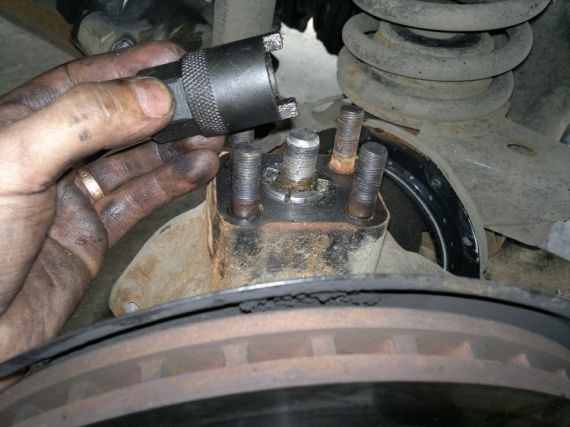
- Press the knevini using the device depicted in the figure and remove the casing of the swivel fist
The order of disassembly of the swivel fist without removing the front axle:
- We put the stops for the rear wheels.
- Domokrata Rayadama front wheel From the right side.
- Perform paragraphs 2-10.
- We will dissemble the swivel lever and the upper lining of the Squorine and remove the lever or the pad with adjusting gaskets.
- We will dissemble the lower lining of the Schworn and remove it with adjusting gaskets.
- Slip the ballproof gland.
- Special adaptation is pressed by a pivot and remove the casing of the swivel fist.