Compliance with the operation mode of batteries, and in particular charging mode, guarantees their trouble-free operation during the entire service life. Charging batteries produce current, the value of which can be determined by the formula
where i is the average charging current, A., and q is the passport electrical capacity of the battery, A-h.
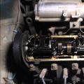
Classical charger For a car battery consists of a lowering transformer, rectifier and charging current regulator. Wire rigs are used as wire regulators (see Fig. 1) and transistor current stabilizers.
In both cases, there are significant thermal power on these elements, which reduces the efficiency of the charger and increases the likelihood of its failure.
For adjustment charging Tok. You can use the condenser store, included in series from the primary (network) winding of the transformer and performing the function of reactive resistances, quenching excess network voltage. Simplified such device is shown in Fig. 2.

In this scheme, the thermal (active) power is allocated only on the VD1-VD4 diodes of the rectifier bridge and the transformer, so the heating of the device is insignificant.
Disadvantage in fig. 2 is the need to ensure the voltage on the secondary winding of the transformer is one and a half times greater than the rated load voltage (~ 18 ÷ 20V).
Charger diagram, providing charging of 12-volt batteries to 15 A, and the charging current can be changed from 1 to 15 A steps 1 A, shown in Fig. 3.

It is possible to automatically turn off the device when the battery is fully charged. It is not afraid of short-term short circuits in the load chain and cliffs in it.
Switches Q1 - Q4 you can connect various combinations of capacitors and thereby adjust the charging current.
A variable resistor R4 set the C2 trigger threshold, which should be triggered at a voltage on the battery clips equal to the voltage of a fully charged battery.
In fig. 4 shows another charger, in which the charging current is smoothly adjustable from zero to the maximum value.

Change current in the load is achieved by adjusting the angle of opening the VS1 trinistore. The adjustment node is made on a single-pass transistor VT1. The value of this current is determined by the position of the engine of the variable resistor R5. The maximum charge current of the battery 10a is installed as an ammeter. The devices are provided on the network side and load fuses F1 and F2.
The variant of the charger printed circuit board (see Fig. 4), the size of 60x75 mm is shown in the following figure:

In the diagram in fig. 4 The secondary transformer winding must be calculated on the current, three times the larger charge current, and, accordingly, the transformer power should also be three times more power consumed by the battery.
The named circumstance is a significant disadvantage of charger with a trinistor current regulator (thyristor).
Note:
VD1-VD4 rectifier bridge diodes and vs1 thyristor must be installed on radiators.
Significantly reduce power loss in trinistore, and consequently, to increase the efficiency of the charger, it is possible that the regulatory element is transferred from the secondary winding chain of the transformer into the primary winding circuit. Such a device is shown in Fig. five.

In the diagram in fig. 5 The adjusting node is similar to the device applied in the previous variant. Trinistor VS1 is included in the diagonal of the VD1 rectifier bridge - VD4. Since the primary transformer winding current is about 10 times less than the charge current, on VD1-VD4 diodes and the VS1 trinistore is relatively small thermal power and they do not require installation on radiators. In addition, the use of trinistora in the transformer primary winding circuit allowed a slightly to improve the shape of the charging current curve and reduce the value of the current curve coefficient (which also leads to an increase in the CPD of the charger). The lack of this charger should include electroplating with the network of the elements of the regulatory assembly, which must be taken into account when developing a constructive design (for example, use a variable resistor with a plastic axis).
The variant of the printed circuit board in line 5, the size of 60x75 mm is shown in the figure below:

Note:
VD5-VD8 rectifier diodes must be installed on radiators.
In the charger in Figure 5, the diode bridge VD1-VD4 type KC402 or KC405 with letters A, B, V. Stabilitron VD3 type KS518, KS522, KS524, or compiled from two identical stabilion with a total stabilization voltage of 16 ÷ 24 volts (KS482, D808 , KS510, etc.). Transistor VT1 single-pass, type KT117A, B, B, G. Diode bridgeiR VD5-VD8 is composed of diodes, with workers current at least 10 amps (D242 ÷ D247, etc.). Diodes are installed on radiators with an area of \u200b\u200bat least 200 sq. Cm, and radiators will be very hot, a fan can be installed in the charger body.
This is very simple scheme Consoles to your existing charger. Which will control the battery charge voltage and when the exhibited level is reached, turn it off from the charger, thereby preventing the battery recharge.
This device has no absolutely noctile details. The whole scheme is built in just one transistor. Has LED indicators displaying status: there is a charge Or battery charged.
Who will fit this device?
Such a device is necessarily useful to motorists. Those who have no automatic charger. This device will make from your conventional charger - fully automatic charger. You no longer have to constantly control the charging of your battery. All you need to do is to put the battery charge, and it will turn off automatically, only after complete charging.Diagram of automatic charger

Here is the actual scheme itself. In fact, this is a threshold relay that works when a certain voltage is exceeded. The trigger threshold is set by the R2 resistor. For fully charged car battery It is usually equal - 14.4 V.
Can download here -
Printed circuit board

How to make a printed circuit board, solve you. It is not complicated and therefore it can easily be thrown on the dumping board. Well, or you can confuse and make on the textolite with etching.
Setting
If all the details of the serviceable setup of the automaton are reduced only to the threshold voltage of the R2 resistor. To do this, connect the scheme to the charger, but do not connect the battery yet. We translate the R2 resistor to the extremely lower position according to the scheme. Install the output voltage on the charge of 14.4 V. Then slowly rotate the variable resistor until the relay works. Everything is configured.We play with the voltage to make sure that the prefix triggers securely at 14.4 V. After that, your automatic charger is ready for work.
In this video, you can see the process of all assembly, adjustment and testing in the work.
Our experienced team of editors and researchers who checked it on accuracy and completeness participated in the creation of this article.
The number of sources used in this article:. You will find their list at the bottom of the page.
The battery provides the car necessary for the installation of auto power supply, it also feeds electrical equipment when the machine is not started. Although the car battery is usually charged while driving by the generator alternating currentThere are cases when the battery is completely discharged and needs to connect the charger. Connecting a charger to a discharged battery requires limit attention, otherwise you can damage the battery or get injured.
Steps
Part 1
Before connecting the chargerCheck out the battery and charger specifications. Read the instructions for the charger for the battery, as well as the car operating manual, part of which is the battery.
Choose a well-ventilated room. In a well-ventilated room, hydrogen is better scattered, which highlights the electrolyte of a sulfuric acid battery inside its compartments. The volatility of hydrogen means the fact that the battery can explode.
Determine which battery terminal is grounded to the car. The battery is grounded by connecting it to the car chassis. In most vehicles, the negative terminal is grounding. Determine the type of terminals in several ways:
Determine whether you will need to remove the battery from the car to recharging it. This information must be specified in the Auto Operation Manual.
Part 2
Connecting a charger- Small signs of corrosion can be cleaned with a round wire brush by placing it on the battery terminals and cleaned them. This brush can be bought at any auto parts store.
- Do not touch the eyes, nose or mouth immediately after cleaning the terminals. Do not touch K. white bloomwhich can be on terminals, as it is frozen sulfuric acid.
-
Pour distilled water into each battery compartment until the water reaches the specified level. This will dare hydrogen from compartments. Perform this step only if you have a free rechargeable battery. Otherwise, follow the manufacturer's instructions.
- Close the caps of the compartments after the water is on them. Sometimes rechargeable batteries Can be equipped with flamestellers. If in your battery there are no plastegical caps, take a wet cloth and put it on top of the covers.
- If the battery compartment covers are sealed, then do not touch them.
-
Put the charger as far as possible from the battery, as far as it allows the length of its cables. Thus, you reduce the possibility of damage to the device from air-carriers portable by air.
Put the switch output voltage switch to the feed voltage position. If there is no voltage data on the battery case, then they can be in the car manual.
- If there is a voltage regulator on your charger, first install it on the most low level Charge.
-
Connect the clips of the charger to the battery. At first, connect the clips to the non-ground terminal (usually a positive terminal). Connecting clips to the grounding terminal depends on whether the battery is in vehicle Or he was removed from it.
Turn off all automotive equipment.
Disconnect the vehicle battery cables. Before removing the battery, you must first disconnect the cable from the ground terminal, and then the cable from the power terminal.
Remove the battery from the car if there is a need.
Clean the battery terminal. Food soda and water with corrosion terminals and neutralize sulfuric acid, which could shed them. You can apply the solution with the help of an old toothbrush.
Now it makes no sense to collect an independent charger for car batteries: in stores a huge selection of finished devices, prices for them are acceptable. However, we will not forget that it is nice to make something useful with your own hands, especially since the simple charger for the car battery is quite possible to collect from the girlfriend, and the price of it will be kopeck.
The only thing that is immediately worth warning is: Schemes without precise current adjustment and output voltage, which do not have a current cut-off at the end of the charge, are suitable for charging only lead-acid batteries. For AGM and the use of such charging leads to damage to the rechargeable battery!
How to make the simplest transformer device
The diagram of this charger from the transformer is primitive, but is operational and assembled from the available parts - the factory chargers of the simplest type are also designed in the same way.

In essence, it is a two-wire rectifier, from here and requirements for the transformer: Since the output of such rectifiers, the voltage is equal to the nominal voltage of the AC, multiplied to the root of two, then at 10v on the transformer winding, we obtain 14.1 V at the output of the charger. The diode bridge is taken by any direct current of more than 5 amps or assemble it of four separate diodes, and the measuring ammeter is also selected to the current. The main thing is to place it on the radiator, which in the simplest case is an aluminum plate at least 25 cm2 area.
The primitiveness of such a device is not only minus: due to the fact that he has no adjustment or automatic shutdownIt can be used for resuscitation of sulfated batteries. But it is not necessary to forget about the absence of protection against cakes in this scheme.
The main problem is where to find a transformer of suitable power (at least 60 W) and with a given voltage. You can use if the Soviet equal transformer is coming. However, its output windings have a voltage of 6.3V, so you will have to connect two sequentially, one of them seems so that in the sum at the output to get 10V. The inexpensive transformer TP207-3 is suitable, in which the secondary windings are connected as follows:

Cut the winding between the terminals 7-8 with the winding.
Eastern electronic adjustment charger
However, you can do without an opening, adding the circuit with an electronic voltage stabilizer at the output. In addition, such a scheme will be more convenient in the garage application, as it will correct the charge current when the supply voltage phases are used, it is used for automotive batteries of a small capacity if necessary.

The role of the regulator here performs the composite transistor Kt837-KT814, the variable resistor adjusts the current at the output of the device. When assembling charging, Stabitron 1N754A can be replaced by Soviet D814a.
The circuit of the adjustable charger is easy to repetition, and is easily assembled by mounting without the need to run the printed circuit board. However, note that field transistors are placed on the radiator, the heating of which will feel. It is more convenient to use old computer coolerBy connecting its fan to the outputs of the charger. The R1 resistor must have a power of at least 5 W, it is easier to wind from nichrome or fechral independently or connect parallel to 10 monovatte resistors for 10 ohms. It can not be placed, but it is impossible to forget that it protects transistors in the event of conclusions.
When selecting a transformer, you can focus on the output voltage of 12.6-16V, take either a slight transformer, connecting two windings successively, or select the finished model with the desired voltage.
Video: The simplest battery charger
Alteration of the charger from a laptop
However, you can do without searches for a transformer, if there is an unnecessary charger from a laptop at hand - with a simple alteration, we will get a compact and easy pulse power supply that can charge automotive batteries. Since we need to get the voltage at the outlet 14.1-14.3 V, no finished power supply will be suitable, but the alteration is simple.
Let's look at the site of a typical scheme, according to which the devices of this kind are collected:

In them, maintaining a stabilized voltage performs a circuit of the TL431 chip, controlling the optocus (not shown in the diagram): as soon as the output voltage exceeds the value that the resistors R13 and R12 are specified, the microcircuit ignites the Opt Apartment LED, according to the PWM controller of the converter to reduce the wellness on the pulse transformer. Hard? In fact, everything is simple to make your own hands.
Open the charger, we find close to the output connector TL431 and two resistors associated with the feet REF. It is more convenient to adjust the upper shoulder of the divider (on the diagram - resistor R13): reducing resistance, we reduce and voltage at the output of the charger, increasing - raise it. If we have a memory of 12 V, we will need a resistor with greater resistance, if the charger is 19 V - then with a smaller one.
Video: Charging for batteries Auto. Protection against short circuit and cakes. Do it yourself
We pull out the resistor and install the trimmer, pre-configured by the multimeter to the same resistance in advance. Then, by connecting the load (light bulb from the headlight) to the output of the charging device, turn on the network and smoothly rotate the rotor engine, while simultaneously controlling the voltage. As soon as we get the voltage in the range of 14.1-14.3 V, we turn off the memory from the network, fix the engine of the trim resistor with varnish (at least for nails) and collect the housing back. It will take no longer than you spent on reading this article.
There are more complex stabilization schemes, and they can already be found in Chinese blocks. For example, here the oppolar is controlled by the TEA1761 microcircuit:

However, the principle of configuration is the same: the resistance of the resistor is changing between the plus output of the power supply and 6 leg of the chip. On the diagram, two polarized resistors are used for this (thus obtained resistance coming out of the standard row). We need to have a stirper instead of them and customize the output to the desired voltage. Here is an example of one of these boards:

By calling, it is possible to understand that the single R32 resistor is interested in this board (collapsed in red) - it is necessary for us to get enough.
Similar recommendations are often found on the Internet, how to make a homemade charger from computer Blok. Nutrition. But consider that all of them are essentially reprints of old articles of the beginning of two thousandths, and similar recommendations for more or less modern blocks Nutrition is not applicable. In them, it is not possible to simply raise the voltage of 12 V to the desired value, as other output voltages are controlled, and they will inevitably "float" with this setting, and will work the power supply protection. You can use laptop charger, outstanding the only output voltage, they are much more convenient for rework.
The theme of automotive chargers is interesting for many. From the article you will learn how to remake the computer power supply into a full-fledged charger for automotive batteries. It will be a pulsed charger for batteries with a capacity of up to 120 a · h, that is, the charging will be quite powerful.
Collect almost nothing needs - just reworked the power supply. It will be added only one component.
A computer power supply has several output voltages. The main power tires have a voltage of 3.3, 5 and 12 V. Thus, the device will need a 12-volt tire (yellow wire) to operate the device.
To charge automotive batteries, the output voltage should be around 14.5-15 V, therefore, 12V from a computer unit is clearly not enough. Therefore, the first thing is necessary to raise the voltage on the 12-volt tire to the level of 14.5-15 V.
Then, you need to collect the adjustable current stabilizer or the limiter so that it is possible to set the necessary charge current.
The charger can be said automatically. The battery will be charged to a predetermined voltage to a stable current. As the current is charged, the current will fall, and at the very end of the process comes with zero.
Getting started to make the device, you must find a suitable power supply. For these purposes, the blocks are suitable in which the TL494 PWM controller is either a full-fledged K7500 analogue.
When the desired block Food is found, you need to check it. To start the block, you need to connect the green wire with any of the black wires.
If the block starts, you need to check the voltage on all tires. If everything is in order, then you need to be removed from the tin case.
After receiving the board, you need to delete all the wires, except for two black, two green and goes to start the block. The remaining wires are recommended to disappear with a powerful soldering iron, for example, 100 watts.
At this stage, all your attention will be required because it is the most important moment In the whole alteration. You need to find the first conclusion of the chip (in the example it is a 7500 chip), and find the first resistor, which is applied from this output to the bus 12 V.
There are many resistors on the first conclusion, but it's not necessary to find it, if you ring all the multimeter.
After finding the resistor (in the example, it is 27 kΩ), it is necessary to disappear only one conclusion. To not confuse, the resistor will be called RX.
Now it is necessary to find a variable resistor, say, on 10 com. Its power is not important. You need to connect 2 wires of length of about 10 cm each in this way:
One of the wires must be connected to the sneened output of the RX resistor, and the second solder to the board in the place where the output of the RX resistor was falling from. Thanks to this adjustable resistor, you can set the necessary output voltage.
Stabilizer or charge limiter is a very important addition that should be in each charger. This node is made on the basis of the operating amplifier. There will be practically any "Operations". The example involves the budget LM358. In the case of this chip, two elements, but only one of them is needed.
A few words about the operation of the current limiter. In this scheme, the operating amplifier is used as a comparator, which compares the voltage on the resistor with low resistance with the reference voltage. The latter is given with the help of Stabitron. And the adjustable resistor now changes this tension.
When changing the voltage value, the operating amplifier will try to smooth out the inputs voltage and will make it by reducing or increasing the output voltage. Thus, the "operator" will control the field transistor. The latter adjusts the output load.
The field transistor is needed powerful, since it will take all the charge current. The example uses IRFZ44, although you can use any other relevant parameters.
The transistor is necessarily installed on the heat sink, because when large currents It will be pretty warm. In this example, the transistor is simply attached to the power supply housing.
The printed fee was divorced on an ambulance handBut it turned out pretty good.
Now it remains to connect everything in the picture and start assembling.
The voltage is set in the area of \u200b\u200b14.5 V. The voltage regulator can not output. To control the front panel there is only a charge current regulator, and the voltmeter is also not needed, since the ammeter will show everything that must be seen when charging.
Ampmeter can take a Soviet analog or digital.
Also on the front panel, a toggle switch was displayed to start the device and output terminals. Now you can consider the project completed.
It turned out uncomplicated in the manufacture and inexpensive charger, which you can safely repeat yourself.
Attached files: