Generator direct current Is an electrical machine that produces a constant voltage.
Behind this quite banal definition lies a very complex device, which is practically the perfection of technical thought. Indeed, since the invention at the end of the 19th century, the device of the DC generator has not undergone significant changes.
No energy arises just like that, out of nowhere. She is always a product of another force. This also applies to electric current. For it to appear, you need a magnetic field that allows you to use the effect of electromagnetic induction - the excitation of EMF in a rotating conductor.
If a load is connected to the ends of the loop of the conductor, inside which the permanent magnet rotates, then an alternating current will flow in it. This will happen because the poles of the magnet are reversed. Based on this effect, they are twin brothers of constant voltage machines.
The whole trick, thanks to which the received current does not change direction, is to have time to switch the load connection points at the same speed as the magnet rotates. This task can only be accomplished by a collector - a special device consisting of several conductive sectors separated by dielectric plates. It is fixed on the anchor of the electric machine and rotates synchronously with it.
The removal of electrical energy from the armature is carried out by brushes - pieces of graphite, which has high electrical conductivity and a low coefficient of sliding friction. At the moment when the conductive sectors of the collector change places, the induced EMF becomes zero, but it does not have time to change sign, since the brush is transferred to the current-collecting sector connected to the other end of the conductor.
As a result, a pulsating voltage of the same magnitude is obtained at the output of the device. Several armature windings are used to smooth out the voltage ripple. The more there are, the less voltage surges at the generator output.
The number of collector current collectors is always twice as many as the armature windings.
Removing the generated voltage from the armature winding, and not the stator, is the fundamental difference between a DC machine and an AC machine. This also predetermined their significant drawback: friction losses between the brushes and the collector, sparking and heating.
Finding out how the unit works
![]() Like any electrical machine, a DC generator consists of an armature and a stator.
Like any electrical machine, a DC generator consists of an armature and a stator.
The armature is assembled from steel plates with recesses in which the windings fit. Their ends are connected to a collector consisting of copper plates separated by a dielectric. The collector, the armature with the windings and the shaft of the electric machine after assembly become a single whole.
The stator of the generator is at the same time its housing, on the inner surface of which several pairs of permanent or electric magnets are fixed. Usually, electrical ones are used, the cores of which can be cast together with the body (for machines low power) or recruited from metal plates.
Also on the case there is a place for fixing the current-collecting brushes.
Depending on the number of magnet poles on the stator, the number of graphite elements also changes. There are as many brushes as there are pairs of poles.
Connection types of electric stator magnets
 DC generators differ in the type of connection of the stator electric magnets. They can be:
- with independent excitement;
- parallel;
- consistent.
When independent excitement electric stator magnets are connected to a self-contained direct current source. This is usually done through a rheostat. The advantage of such a scheme is the ability to adjust the generated electrical power over a wide range. The disadvantage is the need to have an additional power source.
The other two methods are special cases of generator self-excitation, which is possible with a small residual stator magnetism. When parallel work of the DC generator, the stator electromagnets are powered by part of the generated voltage. This is the most common scheme.
When sequential arousal the electromagnet circuit is connected in series with the armature load circuit. The magnitude of the current flowing through the electromagnets substantially depends on the generator load. Therefore, such a circuit is used only for connecting DC traction motors, which, when braking, go into generation mode.
A mixed circuit for connecting the excitation winding is also used - parallel-serial... To do this, each pole of the electromagnet must have two insulated windings (connected in series usually consists of only two or three turns).
Such electrical machines are used in the event that it is required to limit the short-circuit current in the load. For example, in mobile welding units.
The presence of a collector-brush assembly significantly complicates the design of an electric machine. In addition, the transmission of generated energy through it is carried out with great losses and physical activity. Therefore, where possible, DC machines are replaced with a rectifier bridge. Such, for example, are all automotive sources of electricity.
The device and principle of operation of the DC generator in the video
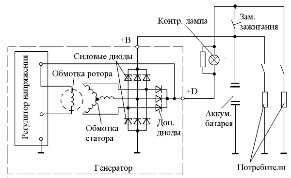
The generator is designed to supply all electrical systems of the vehicle when the engine is running. Although the battery stores a certain amount of energy, it will quickly deplete due to the limited capacity without recharging. All electricity needs, including recharging the battery, are provided by the generator, which is driven by the engine using a belt drive. DC current is required to recharge the battery, so either a DC generator (dynamo) or a generator is needed alternating current with a rectifier.
Currently, only alternators are used on automotive vehicles due to their advantages. However, before the introduction of semiconductors, DC generators were used.
because of design features, such DC electric machines had significant drawbacks, for example, the impossibility of charging the battery when the engine was idling.
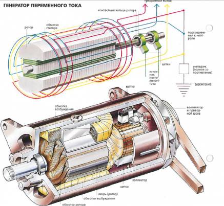
Due to the widespread adoption electrical devices In the design of the car, the increased demand for electricity, the DC generator was not able to satisfy due to the fact that the power had to be removed from the rotating collector with carbon brushes, since the current is induced in the rotor, while the field windings are stationary (Fig. 1 a).
Figure: 1. Schematic diagrams of generators:
a) direct current (stationary magnetic field),
b) alternating current (rotating magnetic field);
1-anchor; 2-collector with brushes; 3-stator;
F - magnetic flux; I-current; ω - angular velocity
At an alternator (Fig. 1 b), the windings in which the main current is formed are stationary, and the excitation windings are light enough and can rotate with significantly more speedthan the rotor of the DC generator. With an appropriate selection of the drive ratio, the rotor of the alternator can rotate at a sufficient speed to idle give positive power to charge the battery.
The transformation of mechanical energy received by the generator from the engine into electrical energy occurs in accordance with the phenomenon of electromagnetic induction. If the changing magnetic flux penetrates the coil with the turns of the conductive wire isolated from each other, then an EMF appears at the terminals of the coil, proportional to the product of the number of turns by the rate of change of the magnetic flux:
E to \u003d -WLBV,
where W - the number of turns of the frame; B - magnetic induction, T; L- length of part of the frame (conductor), m; V- the vector of the linear velocity of the frame movement relative to the stationary magnetic field, m / s.
The minus sign means that if under the action of the EMF E to a current will begin to flow through the frame (when the load is connected), then the magnetic field created by this current will oppose the mechanical force that drives the frame into rotation.
Consider the design and principle of operation of some types of alternators. In auto-tractor generators, the EMF in the coils is induced by changing the magnetic flux of the electromagnet:
By size and direction (brush valve generator);
Only in size (brushless inductor type generator).
The main units of the alternator (Fig. 2), in which the conversion of mechanical energy into electrical energy occurs:- a magnetic system with a field winding and steel sections of the magnetic circuit through which the magnetic flux flows F;
- stator windings, in which EMF is induced when the rotor magnetic flux changes. 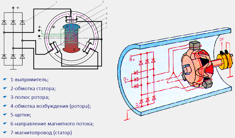
Figure: 2. Schematic diagram valve synchronous generator
The most common type of alternator. In it, a magnetic flux is created excitation winding 4 (Fig. 2) when an electric current flows through it and the system poles 3. The number of poles is always a multiple of two and, as a rule, there are twelve of them in real generator designs.
Poles with excitation winding, ringsthrough which the current from brushes supplied to the excitation winding, shaft and others structural elements form a rotating rotor.
The stator 7 is a magnetic circuit assembled from steel plates. In the grooves of the stationary magnetic circuit is laid stator winding 2, in which electricity... The winding consists of three independent phase windings (Fig. 3), which (conventionally designated by the letters A, B, C) are located on adjacent stator teeth in such a way that the EMF induced in them are displaced relative to each other by 1/3 of the period or 120º. Each phase has six coils in series.
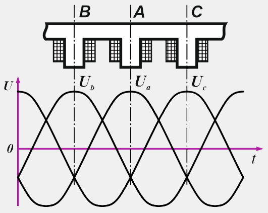
Figure: 3. Displacement of the induced EMF on adjacent stator teeth by 120º
The phase windings can be connected to each other in a star or delta (Fig. 4), but more often a star connection is used, which gives a higher voltage between any pair of terminals compared to a delta connection. The line voltage value is √3 (1.732) of the phase voltage. With a delta connection, the line voltage will be equal to the phase voltage, and the line current will be 1.732 from one pair of coils. Therefore, in high-power generators, a delta connection is often used, since at lower current values, the windings can be wound with a thinner wire, which is more technologically advanced. A thinner wire can also be used for star connections. In this case, the stator winding is made of two parallel windings, each of which is connected to a star, resulting in a "double" star.
The outputs of the phases of the stator winding are connected to the rectifier 1 (Fig. 2).
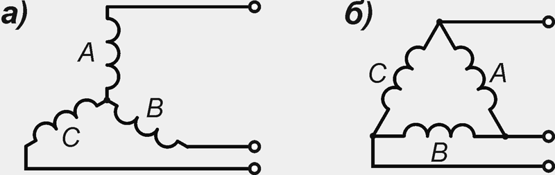
Figure: 4. Connection of windings of phases: a) star; b) a triangle
When the rotor rotates opposite the stator teeth with the phase windings located on them, then the northern N, then the southern S poles of the rotor turn out to be. Magnetic flux F, penetrating the stator windings, changes in magnitude and direction, which, according to Faraday's law, is sufficient for the appearance of an alternating electric voltage at their terminals.
In this case, a variable in magnitude and direction of the EMF will be induced in the phase windings:
E f \u003d 4.44fw k about F,
where f - current frequency, Hz; w- the number of turns of the winding of one phase; k about - winding coefficient, depending on the number of stator slots per pole and phase; F - magnetic flux;
f \u003d pn / 60, k \u003d z / (2pm),
where z - number of grooves; m- number of phases; pIs the number of pole pairs.
In valve generators r usually equal to 6, so the frequency of their alternating current is 10 times less than the rotor speed.
The higher the rotor speed and the greater the magnitude of the magnetic flux, the faster it changes inside the stator phase coils and the higher the voltage induced in them.
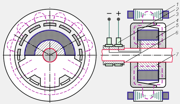
Figure: 5. Diagram of a valve generator with a beak-shaped rotor:
1 stator; 2-brush; 3-stator winding; 4-beak poles;
5-excitation winding; 6-contact rings (manifold); 7-sleeve
Valve generators with beak-shaped rotor (Fig. 5) are synchronous electric car with built-in semiconductor rectifier. The rotor of an automobile valve generator consists of two pole halves, the protrusions (beaks) 4 of which form the north pole system in one half, and the south pole system in the other. The south poles are located between the north poles, and the field winding 5, put on the steel sleeve 7, is sandwiched between the pole halves. The beak-shaped design of the rotor makes it possible to form a multi-pole system with one coil. Thus, the rotor is an electromagnet with a rotating alternating electromagnetic field, the magnetomotive force of which is defined as
F \u003d I in W in,
and can be adjusted by changing the excitation current I atwhere W at - the number of turns of the excitation winding.
Stator package 1 is assembled from electrical steel plates to reduce eddy currents. Three-phase winding coils 3 are placed in the stator slots. The increase in the number of slots per pole and phase allows meeting the high requirements for the sinusoidality of the output voltage and efficiency. With the help of slip rings 6 and brushes 2, current is supplied to the field windings I at to form an alternating magnetic field of the rotor.
In addition, the valve generator (Fig. 6) is equipped with a rectifier unit 3 for rectifying the alternating voltage created in the windings 5 \u200b\u200bof the stator 4, a pulley 14 for driving the rotor and a fan 13 for cooling the heating windings.
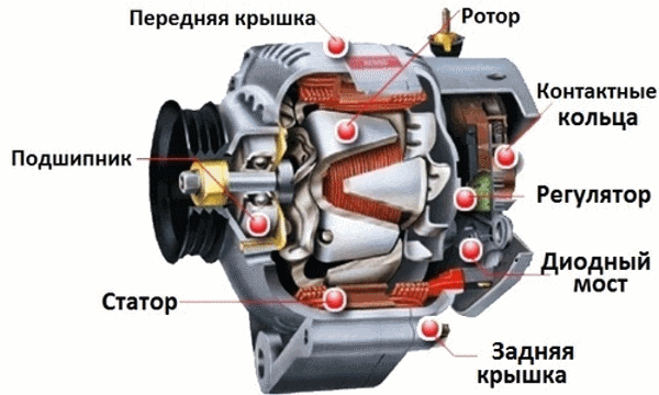
Figure: 6. Alternator:
1-back cover; 2 brushes; 3-diode; 4-stator; 5-stator winding; 6-rolling bearing;
7-collector; 8.9-north and south poles of the electromagnet; 10-rotor winding;
11-front cover; 12 ventilation window; 13-impeller cooling;
14-pulley drive
Currently, in the domestic and foreign industry, many different alternators with a beak-shaped rotor are produced (table 1), which satisfy a wide range of requirements for them.
Table 1
Basic parameters of some generator models
Maud.
gen-ra
No-load speed, rpm
Nom. e.g. V ± 0.5
Nom.
current, A
Add. rectifier
Integ.
regu-r
for example
G222
1250
14,3
there is
37-3701
1100
14,1
there is
there is
16.3701
1100
581.3701
1400
13,9
there is
955.3701
1050
14,2
there is
there is
Inductor generators
The inductor generator is a non-contact, like-pole synchronous AC electric machine with one-sided electromagnetic excitation (Fig. 7). The steel sprocket of the rotor 2 rotates together with the shaft 5, which passes inside the stationary sleeve 8. The excitation winding 7 is fixed on the sleeve, and the stator winding 6 is fixed on the stator teeth. When a direct current passes through the excitation winding, a magnetic flux arises in the magnetic circuit of the generator, lines of force which is shown by a dashed line in Figure 7. The magnetic flux closes through the air gap between the hub and the shaft, the rotor sprocket, the working gap between the rotor and the stator, the stator package, the cover on the field coil side and the thick-walled washer or hub flange.
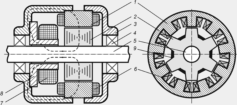
Figure: 7. Diagram of an inductor-type generator:
1-stator magnetic core; 2- rotor (steel sprocket);
3-back cover (the front cover is part of the magnetic circuit);
4-bearing; 5-shaft; 6-stator winding; 7-excitation winding;
8-magnetic inductor system (sleeve with flange); 9-permanent magnet
All sprocket teeth have the same polarity. The change in magnetic flux is associated with a change in the magnetic conductivity of the air gap under the stator teeth. The flux in the stator tooth reaches its maximum value Ф max (Fig. 8), when the axes of the rotor and stator teeth coincide, and decreases to minimum value Ф minwhen the axis of the stator tooth coincides with the axis of the root of the rotor sprocket. Consequently, the magnetic flux in the stator teeth is pulsating and changes only in magnitude without changing direction.
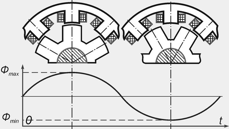
Figure: 8. Change of magnetic flux in the stator tooth over time
For a greater degree of change in the magnetic flux and, therefore, increase the power of the generator, permanent magnets are fixed in the cavities of the rotor sprocket. The inductor generator can be single-phase or multi-phase, it depends on the number of phase stator coils, their location and connection method. In three-phase inductor generators, the stator usually has nine teeth with windings.
The winding of each phase can have several coils connected in series, in parallel and mixed. The phases of the stator winding are connected in a multi-path star or polygon.
The magnitude of the induced EMF depends on the amplitude of the magnetic flux, the number of turns of the stator winding and the frequency n rotation of the rotor. The more the number of turns, the lower the rotor speed the required voltage can be obtained. The amplitude of the magnetic flux depends on the magnitude of the field current of the field winding.
Currently, the domestic industry produces an inductor generator 955.3701 of alternating current with a fixed axial-longitudinal field coil. The generator is equipped with a five-phase stator winding and a five-phase rectifier. The rotor of this generator is made in the form of a six-rayed star made of thin sheets of electrical steel. Permanent magnets are located in the hollows of the star, which contribute to the onset of self-excitation of the generator and somewhat increase its power. Also, in addition to the main excitation winding in this generator there is an additional demagnetizing winding that neutralizes the effect of permanent magnets on high revs generator rotor. The stator winding is located on 10 teeth of the stator magnetic circuit (tooth pitch - 36º) and is divided into five phase sections, two tooth coils in each section. Toothed coils of the same phase section are spaced 180º apart along the stator perimeter.
Other versions of the stator and the connection of the phase windings in inductor generators are also possible. But at present, in terms of such parameters as efficiency, weight, dimensions, inductor generators are inferior to generators with slip rings.
Brushless valve generators
Brushless generators are a development based on a generator design with a beak-shaped rotor (Fig. 9).
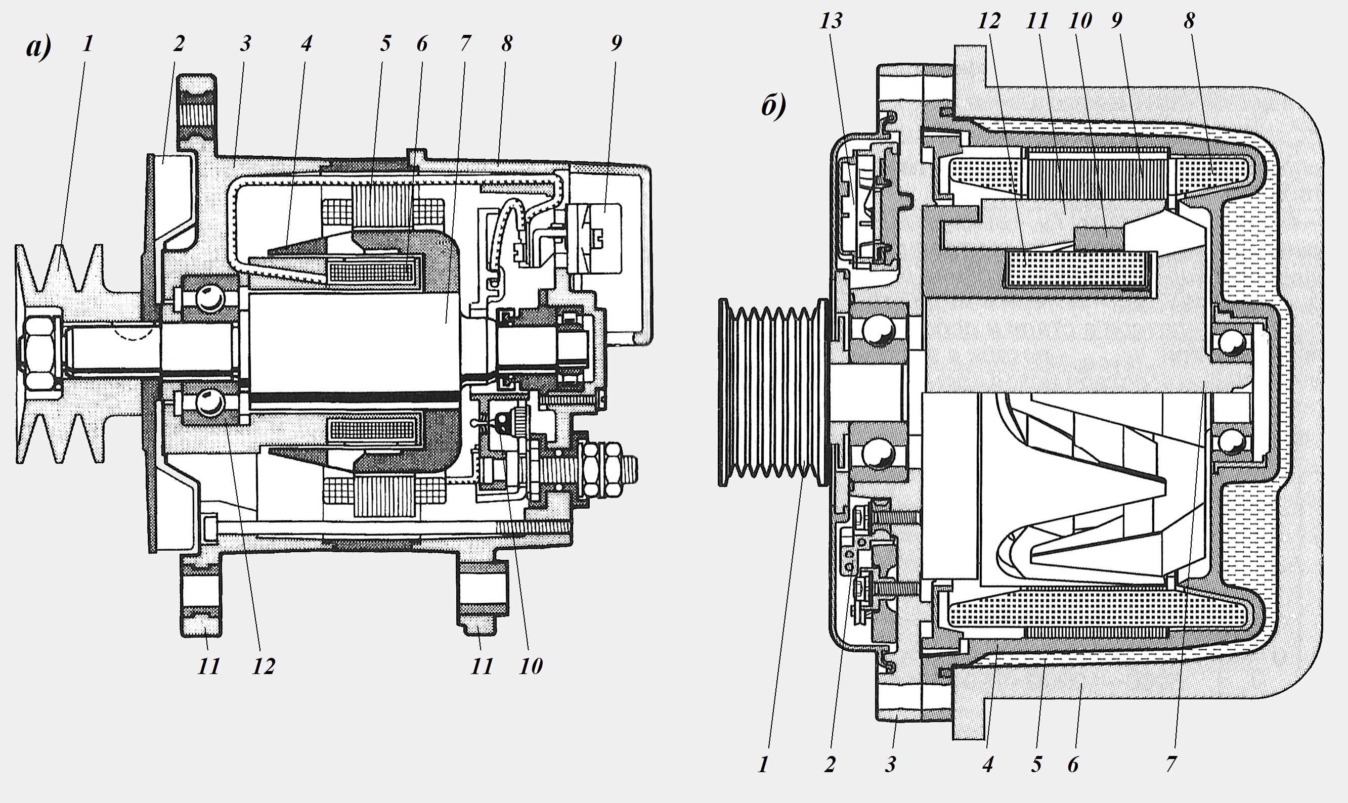
Figure: 9. Brushless generator:
a) with air cooled: 1-pulley; 2-fan; 3-front cover; 4-rotating magnetic circuit; 5-stator; 6-fixed excitation winding; 7-shaft; 8-back cover; 9-voltage regulator; 10-diode; 11-mounting bracket; 12-bearing;
b) with liquid cooling: 1-pulley; 2-rectifier; 3-front cover; 4-generator housing; 5-coolant; 6-jacket cooling jacket; 7-rotor; 8-stator winding; 9-stator; 10-non-magnetic intermediate ring; 11-rotating magnetic circuit (pole); 12-stationary excitation winding; 13-voltage regulator
In generators of this type, only the beak-shaped poles 11 rotate (Fig. 9 b), and the excitation winding 12 remains stationary. One of the pole halves is held against the other by means of a non-magnetic ring 10. The magnetic flux, in addition to the normal working gap, must cross two additional air gaps. Rectifier 2 supplies current to the field winding directly through the voltage regulator 13.
The mass of such generators is somewhat greater than that of brush generators with beak-shaped poles of the same power.
Brushless Generators liquid cooling emit less noise due to the lack of a fan, and are capable of integration with the engine block.
There are also designs of generators with shortened beaks (Fig. 10), which can be obtained constructively if the beak-shaped halves of the pole of the brush generator are pushed apart so that they do not overlap each other and the fastening element 4 (non-magnetic cage) and the electric wires of the field winding are passed into the gap formed 1.
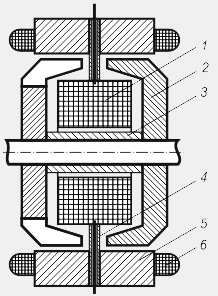
Figure: 10. Schematic of a brushless short-pole valve generator:
1-excitation winding; 2-pole halves with shortened beaks; 3-sleeve;
4-fastening element of the excitation winding; 5-stator; 6-stator winding
The field winding is suspended above the steel sleeve 3 between the two pole halves 2. When the generator shaft rotates, only the magnetized sprockets rotate, however, the area of \u200b\u200btheir pole pieces is small (compared to brush generators), and due to the lower amplitude of the alternating magnetic flux on the stator teeth , electric power generated by such a generator will be lower. But the advantage of the design is the small mass of the rotor, which makes it possible to increase the operating speed of the generator, and, consequently, the power generated by it.
AC rectification
The alternating current of valve generators is rectified by semiconductor silicon diodes. Diodes have two leads and pass current only from the anode lead to the cathode lead when a positive potential is applied to the anode. In the opposite direction, the diodes do not pass current if the reverse voltage does not exceed the permissible value.
In generator rectifiers, diodes of direct and reverse polarity are used. A diode of direct polarity has a cathode connected to the body, and a diode reverse polarity - anode. Depending on the number of phases of the generator, three- and five-phase rectifiers are used.
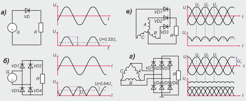
Figure: 11. Rectification of alternator current:
a) half-wave rectification of single-phase alternating current;
b) full-wave rectification of single-phase alternating current;
c) half-wave rectification of three-phase current;
d) full-wave rectification of three-phase current;
G - generator; VD - rectifier (diode); R - load; A, B, C - generator phases
By the shape of the rectified voltage, one- and two-half-wave rectifiers are distinguished. Half-wave single phase rectifiers G (Fig.11 a) AC is provided by one diode VDwhich turns on in series with the load R.
For full-wave rectification of a single-phase current, a bridge rectifier of four diodes is assembled VD1 – VD4 (Fig. 11 b). The positive half-wave (first half-cycle) of the AC voltage opens the diodes VD1 and VD4... In the second half cycle, the diodes are open VD2 and VD3... During the entire operation time of the generator with a bridge rectifier to the load R rectified voltage applied U d one sign.
If one diode is included in each phase of a three-phase valve generator VD1, VD2 and VD3 (Fig. 11 c), you can get a half-wave three-phase rectifier. Each rectifier diode only conducts for 1/3 of the period when voltage is applied to it in the forward direction.
A full-wave three-phase current rectifier has three pairs of diodes - VD1 - VD6 (Fig. 11 d). Diodes form one arm of the rectifier VD1 – VD3 straight polarity, which are connected by cathodes to the positive terminal of the valve generator. Diodes are installed in the second arm of the rectifier VD4 - VD6 reverse polarity. Their anodes are connected to ground. One of the diodes works in the conducting direction VD1, VD2 or VD3, in which the anode has the highest potential, and in the group of diodes VD4 - VD6 - the diode with the lowest potential. When in phase AND voltage is positive and maximum, and in phases AT and FROM voltages are negative and equal, the current into the load R comes through an open diode VD1 and two diodes VD5 and VD6... If phase voltage AND equal to zero, in phase AT - positive, and in phase FROM - negative, diodes conduct current VD2 and VD4... The rest of the diodes do not pass current.
Ripple frequency f p rectified by a full-wave three-phase voltage rectifier U d 6 times the frequency of alternating current.
AC rectification;
Selection of winding data providing the rated voltage at the minimum rotor speed corresponding to the mode idle move engine;
Self-limitation of the strength of the given current.
The main parameters of the valve generator are: rectified voltage U d, rotor speed n and power P (or current strength I dgiven by the generator at a given voltage).
Rectified voltage dependence U d from the excitation currentI in with off load and constant rotor speed n called idling characteristic (fig. 12). In no-load mode, the rectified voltage is equal to the EMF E d... The idling characteristics of valve generators are obtained with independent excitation.
External characteristics of valve generators are the dependence of the rectified voltage U d (Fig. 12 b) from the load current I d at a constant rotor speed, voltage at the terminals of the excitation winding and its resistance. As the load increases, the rectified voltage drops under the action of the armature response, as a result of a decrease in voltage in the stator (armature) circuit and in the rectifier, and the voltage drop in the stator windings is significant and depends on the rotor speed.
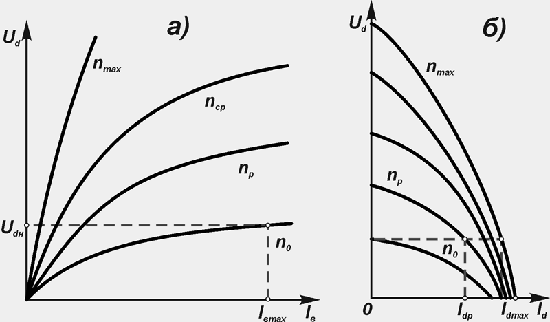
Figure: 12. Characteristics of the valve generator:
a) idle; b) external; n max, n Wed, n p, n 0 - rotor speed, respectively, maximum, average, calculated and recoil start; U dн - rectified rated voltage
External characteristics of valve generators are determined by self-excitation and independent excitation. The decrease in voltage with increasing load occurs not only on the active, but also on the inductive resistance of the stator windings. In the case of self-excitation of the valve generator, the voltage drops on the excitation winding itself. The demagnetizing action of the armature reaction reduces the magnetic flux in the working air gap between the rotor and stator.
By family external characteristics the maximum strength of the rectified current is determined I dmax which is created at a given or regulated voltage value.
The speed control characteristic (Fig.13 a) of the valve generator is the dependence of the excitation current I in on the rotor speed n at constant voltage U gn generator. It is usually determined at several values \u200b\u200bof the load current.
The minimum excitation current is determined at zero load current and the maximum rotor speed of the generator fan. Speed \u200b\u200bcontrol characteristics allow you to determine the range of change in the excitation current from the change in load at constant voltage.
With an increase in the rotor speed n and constant load of the valve generator amperage I in excitation should decrease (Fig. 13 a), and with an increase in the load current - increase (Fig. 13 b).
The generator voltage must be kept constant in the rotor speed range from n 0 before n max in this case, the excitation current will vary from the maximum I bmax to the minimum I вmin values.
The multiplicity of regulation by the excitation current is greater than the multiplicity of regulation by the rotor speed. This is because the magnetization characteristic of the valve generator has a non-linear character, and a deep saturation of the magnetic circuit occurs. The greatest frequency of regulation of the excitation current is possible in the idle mode.
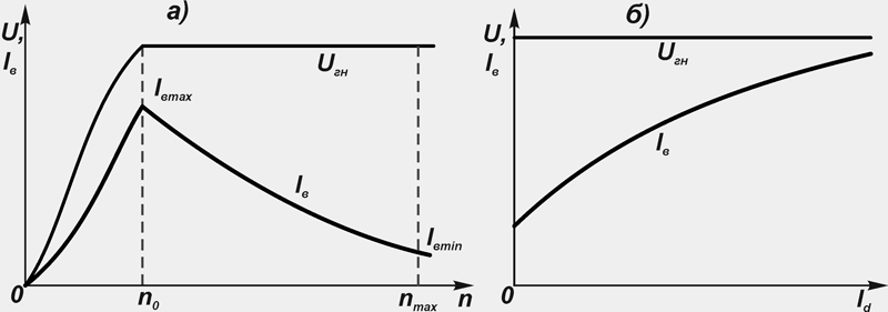
Figure: 13. Dependences of generator voltage and excitation current:
a) from the rotor speed;
b) on the strength of the load current;
U gn - Rated voltage
In connection with the continuous change in the driving mode of the vehicle and, therefore, the rotor speed and the load of the valve generator, the current-speed characteristic of the dependence of the rectified current is important I d, which the valve generator can give to consumers at a given voltage, from the rotor speed n (fig. 14).
The current-speed characteristic is taken at a constant rectified voltage U d \u003d const and constant excitation current I in \u003d const... The control values \u200b\u200bare the initial frequency n 0 generator output, maximum current I dmax at n max... Estimated rotor speeds n p and current strength I dp, are determined at the point of contact of the current-speed characteristic 1 and straight line 2 drawn from the origin. This point corresponds to the maximum value of the ratio of the design power P dp to the calculated rotor speed n p (mode of maximum heating of the valve generator).
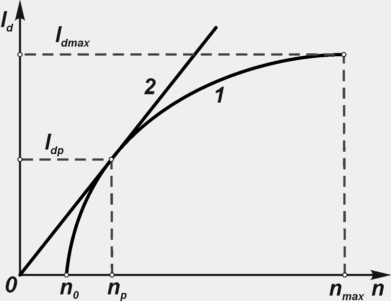
Figure: 14. Current-speed characteristic
The current-speed characteristic is used in the design or selection of a valve generator. It can be determined with independent excitation, self-excitation and operation of a valve generator with a voltage regulator.
All modern car generators have the property of self-limiting maximum current strength. In a wide range of rotor speeds, the current increases slowly, and at the maximum rotor speed it does not exceed the specified maximum value. This is due to the fact that with an increase in the rotational speed of the rotor of the generator, and, consequently, with an increase in the frequency of the current induced in the stator winding, the inductive resistance of the winding increases, therefore the current increases more slowly, asymptotically tending to a certain limiting value.
The transformation of mechanical energy into electrical energy takes place using a current generator. Basically, the practice is the use of rotating electric machine generators. When rotating, an electromotive force is generated in the conductor under the influence of a changing magnetic field. The part of the generator that creates the magnetic field is called the inductor, and the part where the electromotive force is generated is called the armature.
Operating principle
The rotating part of the generator is called the rotor, and the stationary part is the stator. The alternator has a stator and a rotor, which, by their design, can be both an armature and an inductor.
Almost all the electricity in the world's power plants is produced by alternating current generators. When the inductor rotates, a magnetic field is created, which rotates and induces a variable electromotive force in the stator winding. Its frequency fully coincides with the rotor speed.
Generator elements
The stator magnetic system consists of thin steel sheets pressed into a package. The stator winding is located in the grooves of this package. It includes three phases shifted relative to each other by one third of the stator perimeter. The electromotive forces induced in the phase windings are also shifted among themselves by 1200. Each phase has a winding consisting of coils with many turns connected in parallel or in series. The parts of the coils protruding from the slots are called stator end connections.
In the inductor and stator, the number of poles can be more than two. The number of poles depends entirely on the rotor speed. When slowing down, the rotor may have an increasing number of poles.
The massive steel rotor core contains the excitation winding of the generator. This design is applicable to AC generators operating with high frequency rotation. This is due to the fact that at high speeds rotation, the rotor winding is subject to large centrifugal forces. A large number of poles implies a separate excitation winding at each pole, which is typical for power generators operating at low speeds.
In water turbines, alternators may be of a vertical shaft design. When operating, depending on the power, air, hydrogen, water or oil cooling can be used.
An alternator or direct current generator is a device for generating electricity by converting mechanical energy.
What an alternator looks like
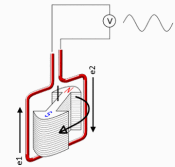
How does an alternator work? A current is generated in a conductor by a magnetic field. It is convenient to generate current if you rotate a rectangular conductive frame in a stationary field or a permanent magnet inside it.
When it rotates around the axis of the magnetic field it creates inside the frame with angular velocity ω, the vertical sides of the contour will be active since they are crossed by the magnetic lines. There is no action on the horizontal sides coinciding in the direction with the magnetic field. Therefore, no current is induced in them.
What does a generator with a magnetic rotor look like?
EMF in the frame will be:
e = 2 B max lv sin ωt,
B max - maximum induction, T;
l - frame height, m;
v - frame speed, m / s;
t - time, s.
Thus, from the action of the changing magnetic field in the conductor, an alternating EMF is induced.
For a large number of turns wby expressing the formula in terms of the maximum flow F m, we get the following expression:
e = wF m sin ω t.
The principle of operation of another type of alternator is based on the rotation of a conductive frame between two permanent magnets with opposite poles. The simplest example is shown in the figure below. The voltage appearing in it is removed by slip rings.
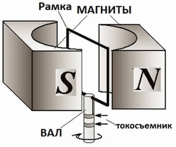
Permanent magnet current generator
The use of the device is not very common due to the load of moving contacts high currentpassing through the rotor. The design of the first given version also contains them, but much less direct current is supplied through them through the turns of the rotating electromagnet, and the main power is removed from the stationary stator winding.
Synchronous generator
A feature of the device is the equality between the frequency f, induced in the stator EMF and rotor speed ω :
ω \u003d 60 ∙f/ p rpm,
where p - the number of pole pairs in the stator winding.
The synchronous generator creates an EMF in the stator winding, the instantaneous value of which is determined from the expression:
e \u003d 2π B max lwDn sinω t,
where land D - length and inner diameter of the stator core.
The synchronous generator produces a voltage with a sinusoidal characteristic. When connected to its terminals C 1, C 2, C 3 consumers, a single or three-phase current flows through the circuit, the circuit is below.
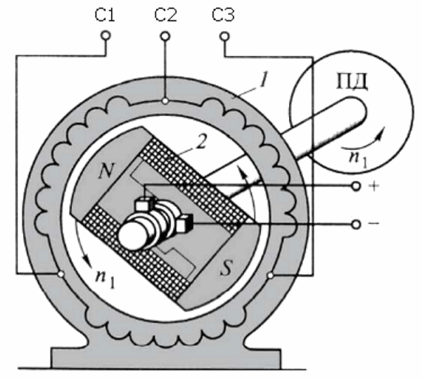
Three-phase synchronous generator circuit
The action of the changing electrical load also changes the mechanical load. This increases or decreases the speed of rotation, resulting in a change in voltage and frequency. To prevent such a change from happening, electrical characteristics automatically maintain at a given level through the voltage and current feedbacks on the rotor winding. If the rotor of the generator is made of a permanent magnet, it has a limited ability to stabilize the electrical parameters.
The rotor is forced to rotate. An induction current is supplied to its winding. In the stator, the rotor magnetic field, rotating at the same speed, induces 3 alternating EMFs with a phase shift.
The main magnetic flux of the generator is created by the action of a direct current passing through the rotor winding. Power may come from another source. The self-excitation method is also common, when a small part of the alternating current is taken from the stator winding and passes through the rotor winding after pre-straightening. The process is based on residual magnetism, which is sufficient to start the generator.
The main devices that generate almost all of the world's electricity are synchronous hydro or turbine generators.
Asynchronous generator
The device of an asynchronous type alternator differs in the difference in the EMF rotation frequency ω and rotor ω r. It is expressed through a coefficient called slip:
s \u003d (ω - ω r) / ω.
In operating mode, the magnetic field slows down the rotation of the armature and its frequency is lower.
An asynchronous motor can operate in a generator mode if ω r\u003e ω, when the current changes direction and energy is given back to the network. Here the electromagnetic moment becomes braking. The use of this property is common when lowering loads or on electric vehicles.
An asynchronous generator is chosen when the requirements for electrical parameters are not very high. In the presence of inrush overloads, a synchronous generator is preferable.
Device car generator is no different from the usual, generating electric current. It generates alternating current, which is then rectified.
What a car generator looks like
The design consists of an electromagnetic rotor rotating in two bearings driven by a pulley. It has only one winding, with direct current supply through 2 copper rings and graphite brushes.
The electronic relay regulator maintains a stable voltage of 12V, independent of the rotation speed.
Automotive generator circuit
The current from the battery goes to the rotor winding through the voltage regulator. The moment of rotation is transmitted to it through the pulley and EMF is induced in the turns of the stator winding. The generated three-phase current is rectified by diodes. Maintaining a constant output voltage is performed by a regulator that controls the excitation current.
As the motor rises, the excitation current decreases, which helps to maintain a constant output voltage.
Classic generator
The design contains a liquid fuel engine that drives a generator. The rotor speed must be stable, otherwise the quality of electricity generation decreases. When the generator is worn out, the rotation speed becomes lower, which is a significant disadvantage of the device.
If the load on the generator is below the rated load, it will partially idle, consuming excess fuel.
Therefore, it is important when purchasing it to make an accurate calculation of the required power so that it is correctly loaded. A load below 25% is prohibited, as this affects its durability. All possible operating modes that must be observed are indicated in the passports.
Many kinds of classic models have acceptable prices, high reliability and a large power range. It is important to load it properly and have it inspected on time. The picture below shows the models of gasoline and diesel generators.
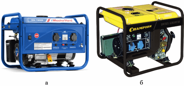
Classic generator: a) - gasoline generator, b) - diesel generator
Diesel generator
The generator drives the engine, which runs on diesel fuel... The internal combustion engine consists of a mechanical part, a control panel, a fuel supply system, cooling and lubrication. The power of the generator depends on the power of the internal combustion engine. If it is required small, for example, for household appliances, it is advisable to use a gasoline generator. Diesel generators are used wherever more power is needed.
ICEs are used in most cases with overhead valves. They are more compact, more reliable, easy to repair, and emit less toxic waste.
They prefer to choose a generator with a metal case, since plastic is less durable. Devices without brushes are more durable, and the generated voltage is more stable.
Capacity fuel tank provides operation at one gas station no more than 7 hours. In stationary installations, an external tank with a large volume is used.
Gas generator
As a source of mechanical energy, the most common four-stroke carburetor engine... Mostly used models from 1 to 6 kW. There are devices up to 10 kW, capable of providing a country house at a certain level. Prices gasoline generators are acceptable, and the resource is quite sufficient, although less than that of diesel engines.
The generator is selected depending on the loads.
For high starting currents and frequent use of electric welding, it is better to use a synchronous generator. If you take an asynchronous generator more powerful, it will cope with inrush currents. However, it is important here that it is loaded, otherwise gasoline will be consumed irrationally.
Inverter generator
Machines are used where electricity is required high Quality... They can work continuously or at intervals. The objects of energy consumption here are institutions where power surges are not allowed.
The basis of the inverter generator is the electronic unitwhich consists of a rectifier, a microprocessor and a converter.
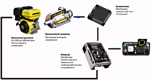
Block diagram of an inverter generator
Power generation starts in the same way as in the classic model. First, an alternating current is generated, which is then rectified and fed to the inverter, where it again turns into alternating current, with the desired parameters.
The types of inverter generators differ in the nature of the output voltage:
- rectangular - the cheapest, capable of powering only power tools;
- trapezoidal impulse - suitable for many devices, with the exception of sensitive equipment (middle price category);
- sinusoidal voltage - stable characteristics suitable for all electrical appliances (highest price).
The advantages of inverter generators:
- small size and weight;
- low fuel consumption by regulating the generation of the amount of electricity that consumers need at the moment;
- the possibility of short-term work with overload.
The disadvantages are high prices, sensitivity to temperature changes of the electronic part, low power. In addition, it is expensive to repair the electronic unit.
The inverter model is selected in the following cases:
- the device is purchased only in cases where a conventional generator is not suitable, since its price is high;
- power is required no more than 6 kW;
- for permanent use, classic versions of generators are better;
- it is necessary to partially supply household appliances with electricity;
- for domestic use, it is better to use single-phase devices.
Video. Alternator.
Alternators are capable of replenishing electricity in the house in the event of a stationary device failure, and are also used anywhere where electricity is needed.
In order to ensure the most comfortable existence, man has developed and invented a huge variety of different technological devices and complex systems. But one of the most efficient and effective devices for using electricity has become an alternator. Get acquainted with the types and types of RCDs.
Today, there are two main types of construction:
- Devices with a fixed part - a stator and a rotating element - a magnetic pole. The elements of this type widely used among the population, because the presence of a fixed winding saved the user from the need to remove unnecessary electrical load.
- An electrical device with a rotary armature and a fixed magnetic pole.
It turns out that the design of the generator is reduced to the presence of two main parts: movable and fixed, as well as to the elements that serve as a connecting link between them (brushes and wires).
Principle of operation
The working principle of the car alternator:
- the rotating part of the rotor or drive mechanism is nominally taken as an electric magnet. It is he who will transfer the created magnetic field to the stator "body". This is an external element of the device, which consists of coils with wires connected to them.
- voltage is transmitted through rings and manifold shields. The rings are made of copper and rotate simultaneously with the rotor and crankshaft. In the course of movement, the brushes are pressed against the surface of the rings. Consequently, the current will be transferred from the stationary part to the moving part of the system.
Specifications
When buying an alternator, you need to focus on the following specifications:
- Electric power;
- Working voltage;
- The number of revolutions of the rotating part of the generator;
- Useful power factor;
- Current strength.
These values \u200b\u200bare basic technical characteristics alternating current.
Kinds
Today on the territory Russian Federation realize the sale different types certified and unlicensed alternators. Household overview halogen lamps and how to choose here:. The most popular of these devices are the following: