And others. High reliability requirements are imposed on car generators, as the generator provides smooth operation most of the components of a modern car.
Device and general principle of operation
On the first cars, DC collector generators were used, the collector assembly of which was unreliable. But with the advent of powerful rectifier semiconductor diodes, this circuit was moved to a more reliable version.
In modern cars, synchronous three-phase AC electric machines are used, and a three-phase rectifier according to the Larionov scheme is used in the rectifier.
Due to the variable speed of the car engine and the switching of electrical consumers in on-board network, it becomes necessary to maintain the voltage level. For these purposes, a voltage regulator is used that controls the current in the excitation winding of the generator.
In order for the generator to start generating electrical energy after starting the engine, it is necessary to apply voltage to the field winding. This happens when the ignition switch is turned to the "ON" position. The current in the excitation winding is regulated by a voltage regulator (in some cars - a separate unit installed in engine compartment, in many modern ones it is built directly into the generator). The alternator rotor is driven by a V-belt pulley. The electromagnetic field generated by the excitation winding induces electricity in the power winding.
The voltage of the on-board network with the generator running and a working voltage regulator is maintained at the level of 13.5-14.5. This is above the voltage level of the battery, which causes a small equalization current to charge the battery.
Why, by the way, 14 volts? The battery seems to be 12-volt, the whole electrician is also called "twelve-volt"? It's a tricky battery device. If you limit the generator voltage to 12 volts, the battery will constantly strive to give its current to the network, naturally, constantly discharging. A slightly increased voltage makes it ... start, on the contrary, charging from the generator.
At generator poles (located on the stator), made of electrical steel, there is a field winding. At the anchor of the generator there is a power winding, from which the electric current is removed by means of a collector with brushes. The field winding and the armature winding are connected in parallel, the relay-regulator is included in the field winding circuit.
The relay-regulator consists of three electromagnetic relays:
Rotor car generator alternating current has a field winding (at the generator direct current the excitation winding is on the pole cores), the current is supplied through the brushes and slip rings. The stator has three star-connected windings. The current taken from the stator is rectified by six semiconductor diodes (built into the rectifier board) and becomes constant. Further, the rectified current enters the on-board electrical network of the car.
The voltage regulator regulates the field current so that the voltage taken from the generator is as stable as possible.
Voltage regulators for alternators can be vibrating (only electromagnetic relays), contact transistor (electromagnetic relays controlled by a transistor circuit) or contactless (there is no electromagnetic relay, the current is regulated by an electronic key on transistors). Design - made in a separate housing or built into the generator.
For example, on a GAZ-53 car, a contact-transistor voltage regulator PP-362 (generator G-250) is used, on a VAZ-2101 - a vibration voltage regulator PP-380 (generator G-221), and on a Moskvich-2140 car - contactless regulator voltage RR-362A, built into the G-250Zh generator.Current limiter, reverse current relay and closing relay control lamp the generator as such is absent, semiconductor rectifier diodes cope with their work.
The use of alternators can reduce dimensions, the weight of the generator, to increase its reliability, while maintaining or even increasing its power in comparison with DC generators.
For example, the G-12 DC generator (GAZ-69 car) weighs 11 kg, the rated current is 20 amperes, and the G-250P2 alternating current generator (UAZ-469 car) with a mass of 5.2 kg produces a rated current of 28 amperes.Generators for motorcycle and agricultural machinery
On motorcycles with a transverse engine (for example, motorcycles "IZH"), the generator rotor is mounted on the front end crankshaft (right in the direction of travel), the generator is located in the combined crankcase of the engine and gearbox, closed with a cover. Usually, parts of the ignition system are combined with the parts of the generator (breaker contacts or contactless sparking torque sensor electronic system ignition)
"Lighting up"
When "lighting" the car generator of the donor car (especially the voltage regulator) may fail. The fact is that the current consumed by an electric starter is much higher than the maximum current for which the generator and voltage regulator are designed.
For example, the ST-221 (VAZ-2101) starter has a capacity of 1.77 liters. from. , current strength idle move 35 amperes, in full braking mode 500 A. The G-221 generator of the same car is designed for a maximum current of 42 A.- On vehicles with diesel engines that have a hydraulic brake system with a vacuum booster, a vane vacuum pump is installed at the rear end of the generator. The fact is that on cars with gasoline engines, the vacuum generated behind the throttle valve is used to operate the amplifier; diesel engines, of course, do not have this valve. The vacuum pump is included in the engine lubrication system.
- The power required to power the field winding of an automobile generator is typically 1/20 of its rated output power.
- For rotation of the magnetized rotor of an unloaded generator and the appearance of a rated voltage at its output, approximately 1/20 of its rated output power is spent.
- Only under load (lamps, radio tape recorder, battery charging) does the generator shaft offer significant resistance to rotation, since its own magnetic field appears around its stator winding, which interacts with the rotor field.
- An easy way to test the voltage regulator is to measure the voltage across car battery before and after starting the engine. Before starting, the voltage will be 12 volts, after starting it should be slightly higher.
- On modern cars, the engine control unit automatically raises idle speed when any electrical consumers are switched on.
- On heavy vehicles with diesel engines two 12-volt batteries connected in series are installed (where a 24-volt circuit is used). It may turn out that one battery is overcharging (boiling), and the other is not sufficiently charged. The fact is that it is almost impossible to find two completely identical batteries (in terms of internal resistance). In this case, it may be enough to swap the batteries in order to restore normal charge.
Literature
- Koryagin A.P., Soloviev G.M. The device, service and traffic rules. Military publishing house of the USSR Ministry of Defense, Moscow, 1957.
- A quick car guide, State Research Institute road transport, Moscow, 1983.
Characteristics of automotive alternators
The ability of a generator set to provide consumers with electricity at various operating modes of the engine is determined by its current-speed characteristic (TCX) - the dependence of the maximum current given by the generator on the rotor speed at a constant voltage on the power terminals. In fig. 1 shows the current-speed characteristic of the generator.
Figure: 1. Current-speed characteristic of generating sets.The graph has the following characteristic points:
n0 is the initial rotor speed without load, at which the generator starts to deliver current;
Iхд - generator recoil current at a speed corresponding to the minimum stable idle speed of the engine.
On modern generators, the current delivered in this mode is 40-50% of the nominal;
Idm - maximum (rated) recoil current at a rotor speed of 5000 min "" (6000 min "" for modern generators).
Distinguish TLC, defined: - with self-excitation (the excitation winding circuit is powered by its own generator);
With independent excitation (the excitation winding circuit is powered from an external source);
For a generator set (voltage regulator included in the circuit);
For a generator (voltage regulator disabled);
In a cold state (cold is understood as a state in which the temperature of the generator nodes is practically equal to the ambient temperature (25 ± 10) ° С, since during the experimental determination of TLC the generator heats up, the experiment time should be minimal, i.e., not more than 1 min , and a repeated experiment should be carried out after the temperature of the nodes again becomes equal to the ambient temperature);
In a heated state.
The technical documentation for generators often does not indicate the entire TLC, but only its individual characteristic points (see Fig. 1).
These points include: - initial idle speed n0. It corresponds to the generator set voltage without load;
Maximum current delivered by the generator Idm. (Automotive valve generators are self-limiting, i.e., having reached Idm, the value of which is close to the value of the short-circuit current, the generator, with a further increase in the speed of rotation, cannot deliver more current to consumers. );
Rotation frequency npn and current Idn in design mode. (The point of the design mode is determined at the point where the TCX touches the tangent drawn from the origin. The approximate calculated value of the current strength can be determined as 0.67 Idm The design mode corresponds to the maximum mechanical moment of the generator and in the region of this mode the largest heating of the nodes is observed, since with increasing the rotation frequency increases the current of the generator and, consequently, the heating of its nodes, but at the same time the intensity of cooling of the generator by a fan located on its shaft also increases.
Rotational speed nхд and current strength Iхд in the mode corresponding to idling of the engine internal combustion (ICE). In this mode, the generator must deliver the amperage required to power a number of the most important consumers, primarily ignition in carburetor ICEs.
How to determine the parameters of your generator: For domestic generators: For new models domestic engines (VAZ-2111, 2112, ZMZ-406, etc.): generators of compact design are installed (94.3701, etc.). Brushless (inductor) generators (955.3701 for VAZ, G700A for UAZ) differ from the traditional design in that they have permanent magnets on the rotor, and the field windings are on the stator (mixed excitation). This made it possible to do without the brush assembly (the vulnerable part of the generator) and slip rings. However, these generators have a slightly higher mass and a higher noise level.
The generator panel usually indicates its main parameters:
Rated voltage 14 or 28 V (depending on the rated voltage of the electrical system);
Rated current, which is taken as the maximum output current of the generator.
Type, brand of generator
The main characteristic of a generator set is its current-speed characteristic (TLC), that is, the dependence of the current supplied by the generator to the network on the speed of its rotor at a constant voltage at the generator power terminals.
This characteristic is determined when the generator set is operating complete with a fully charged storage battery with a nominal capacity expressed in A / h, which is at least 50% of the nominal current of the generator. The characteristic can be determined in cold and hot states of the generator. In this case, the cold state is understood as one in which the temperature of all parts and nodes of the generator is equal to the temperature environment, the value of which should be 23 ± 5 ° С. The air temperature is determined at a point 5 cm from the generator air intake. Since the generator heats up during the characterization due to the power losses released in it, it is methodically difficult to remove the TLC in a cold state, and most firms give the current-speed characteristics of the generators in a heated state, i.e. in a state in which the components and components of the generator are heated in each determined point to a steady-state value due to the power losses released in the generator at the above-mentioned cooling air temperature.
The range of speed variation when taking the characteristic is between the minimum frequency at which the generating set develops a current of 2A (about 1000 min-1) and the maximum. The characteristic is taken at intervals of 500 to 4000 min-1 and 1000 min-1 with more high frequencies... Some companies give the current-speed characteristics determined at the rated voltage, i.e. at 14 V, typical for cars. However, it is possible to remove such characteristics only with a regulator specially reconstructed to a high voltage maintenance level. To prevent the voltage regulator from operating when the current-speed characteristic is taken, it is determined at voltages Ut \u003d 13.5 ± 0.1 V for a 12-volt onboard system... An accelerated method for determining the current-speed characteristic is also allowed, requiring a special automated stand, in which the generator warms up for 30 minutes at a rotational speed of 3000 min-1, corresponding to this frequency, current strength and the voltage indicated above. The time to take the characteristic should not exceed 30 s with a constantly changing speed.
The current-speed characteristic has characteristic points, which include: n0 is the initial no-load speed. Since usually the characterization begins with the load current (about 2A, this point is obtained by extrapolating the measured characteristic to the intersection with the abscissa axis.
nL is the minimum operating speed, i.e. the speed approximately corresponding to the idle speed of the engine. It is conventionally accepted, nL \u003d 1500 min-1. The current IL corresponds to this frequency. Bosch has adopted nL \u003d 1800 min-1 for "compact" generators. Typically IL is 40 ... 50% of the rated current.
nR is the rated speed at which the rated current IR is generated. This speed is taken nR \u003d 6000 min-1. IR is the smallest amperage that the generator set must supply at nR.
NMAX is the maximum speed. At this speed, the generator generates a maximum current Imax. Usually, the maximum current strength differs little from the nominal IR (no more than 10%).
Manufacturers give in their information materials mainly only characteristic points of the current-speed characteristic. However, for generator sets of cars with a sufficient degree of accuracy, it is possible to determine the current-speed characteristic from the known nominal current value IR and the characteristic according to Fig. 8, where the generator current values \u200b\u200bare given in relation to its nominal value.
In addition to the current-speed characteristic, the generator set is also characterized by the self-excitation frequency. When the generator is running on a car, complete with a storage battery, the generator set must self-excite at an engine speed lower than its idle speed. In this case, of course, the circuit must include a lamp for monitoring the operating state of the generator set with the power specified for it by the manufacturer of the generator and resistors parallel to it, if they are provided by the circuit.
Another characteristic by which it is possible to represent the energy capacity of the generator, that is, to determine the amount of power taken by the generator from the engine, is the value of its efficiency, determined in the modes corresponding to the points of the current-speed characteristic (Fig. 8), the value of the efficiency by Fig. 8 is shown for orientation, because it depends on the design of the generator - the thickness of the plates from which the stator is assembled, the diameter of the slip rings, bearings, the resistance of the windings, etc., but mainly on the power of the generator. The more powerful the generator, the higher its efficiency.
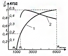 Fig. 8 Output characteristics of automotive generators:
1 - current-speed characteristic, 2 - efficiency by points of current-speed characteristic
Finally, the generator set is characterized by the range of its output voltage, with changes within certain limits of speed, load current and temperature. Usually, the prospectuses of companies indicate the voltage between the power terminal "+" and the "mass" of the generator set at the control point or the voltage of the regulator setting when the generator set is cold at a speed of 6000 min-1, a load with a current of 5 A and work complete with a battery. as well as temperature compensation - change regulated voltage depending on the ambient temperature. Thermal compensation is indicated as a coefficient characterizing the voltage change when the ambient temperature changes by ~ 1 ° C. As shown above, the voltage of the generator set decreases with increasing temperature. For passenger cars, some companies offer generator sets with the following regulator setting voltage and temperature compensation:
Setting voltage, V ................................. 14.1 ± 0.1 14.5 + 0, 1
Thermal compensation, mV / ° С ............................... -7 + 1.5 -10 ± 2
Generators drive
The generators are driven from the crankshaft pulley by a belt drive. The larger the pulley diameter by crankshaft and the smaller the diameter of the generator pulley (the ratio of the diameters is called the gear ratio), the higher the generator speed, respectively, it is able to deliver more current to consumers.
V-belt drive is not applicable for gear ratios greater than 1.7-3. First of all, this is due to the fact that with small diameters of pulleys, the V-belt is heavily wears out.
On modern models, as a rule, the drive is carried out by a poly V-belt. Due to its greater flexibility, it allows the generator to be fitted with a small diameter pulley and therefore obtain higher gear ratios, i.e. high speed generators. The tension of the poly V-belt is carried out, as a rule, tension rollers with a stationary generator.
Mounting the generator
The generators are bolted to the front of the engine on special brackets. The mounting feet and tensioning lug of the generator are located on the covers. If the attachment is carried out with two paws, then they are located on both covers, if there is one paw, it is on the front cover. There is usually a spacer sleeve in the hole of the rear leg (if there are two mounting legs), which eliminates the gap between the engine bracket and the leg seat.
Voltage regulators
Regulators maintain the generator voltage within certain limits for optimal operation of electrical appliances included in the vehicle's on-board network. All voltage regulators have measuring elements, which are voltage sensors, and actuators that regulate it.
In vibration regulators, the measuring and actuating element is an electromagnetic relay. In contact transistor controllers, the electromagnetic relay is located in the measuring part, and the electronic elements are in the executive part. These two types of regulators are now completely replaced by electronic ones.
Semiconductor non-contact electronic controllers are usually built into the generator and combined with the brush assembly. They change the excitation current by changing the time when the rotor winding is switched on to the supply network. These regulators are not subject to misalignment and do not require any maintenance, except for checking the reliability of contacts.
Voltage regulators have the property of thermal compensation - changes in the voltage supplied to the battery, depending on the air temperature in the engine compartment for optimal battery charging. The lower the air temperature, the more voltage must be supplied to the battery and vice versa. The value of thermal compensation reaches up to 0.01 V per 1 ° C. Some models of remote controllers (2702.3702, РР-132А, 1902.3702 and 131.3702) have step manual voltage level switches (winter / summer).
The principle of operation of the voltage regulator
All gensets are now equipped with semiconductor electronic voltage regulators, usually built into the generator. The schemes of their execution and design may be different, but the principle of operation is the same for all regulators. The voltage of a generator without a regulator depends on the frequency of rotation of its rotor, the magnetic flux created by the excitation winding, and, consequently, on the strength of the current in this winding and the magnitude of the current given by the generator to consumers. The higher the rotational speed and the excitation current, the higher the generator voltage, the higher the current of its load, the lower this voltage.
The function of the voltage regulator is to stabilize the voltage when the speed and load change by acting on the excitation current. Of course, you can change the current in the excitation circuit by introducing an additional resistor into this circuit, as was done in the previous vibration voltage regulators, but this method is associated with a loss of power in this resistor and is not used in electronic regulators. Electronic controllers change the excitation current by turning on and off the excitation winding from the mains, while the relative duration of the excitation winding switching-on time changes. If, to stabilize the voltage, it is required to reduce the excitation current, the time to turn on the excitation winding decreases, if it is necessary to increase it, it increases.
It is convenient to demonstrate the principle of operation of the electronic regulator on a fairly simple diagram of the EE 14V3 type regulator from Bosch, shown in Fig. nine:
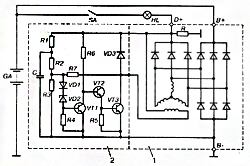 Fig. 9 BOSCH EE14V3 voltage regulator circuit:
1 - generator, 2 - voltage regulator, SA - ignition switch, HL - control lamp on the instrument panel.
To understand the operation of the circuit, you should remember that, as shown above, the Zener diode does not pass current through itself at voltages below the stabilization voltage. When the voltage reaches this value, the zener diode "breaks through" and current begins to flow through it. Thus, the Zener diode in the regulator is a voltage standard with which the generator voltage is compared. In addition, it is known that transistors pass current between the collector and the emitter, i.e. open, if the current flows in the base-emitter circuit, and this current does not pass; closed if the base current is interrupted. The voltage to the Zener diode VD2 is supplied from the output of the generator "D +" through a voltage divider across the resistors R1 (R3 and the diode VD1, which performs temperature compensation. While the voltage of the generator is low and the voltage on the Zener diode is lower than its stabilization voltage, the Zener diode is closed, through it, and, therefore, and the current does not flow in the base circuit of the transistor VT1, the transistor VT1 is also closed.In this case, the current through the resistor R6 from the "D +" terminal enters the base circuit of the transistor VT2, which opens, through its emitter-collector junction current begins to flow in the base of the transistor VT3 In this case, the excitation winding of the generator is connected to the supply circuit through the emitter-collector transition VT3.
The connection of transistors VT2 and VT3, in which their collector leads are combined, and the power supply of the base circuit of one transistor is produced from the emitter of the other, is called the Darlington circuit. With this connection, both transistors can be considered as one high gain composite transistor. Usually such a transistor is performed on a single silicon crystal. If the voltage of the generator has increased, for example, due to an increase in the frequency of rotation of its rotor, then the voltage on the Zener diode VD2 also increases, when this voltage reaches the stabilization voltage, the Zener diode VD2 "breaks through", the current through it begins to flow into the base circuit of the transistor VT1, which the emitter also opens with its transition - the collector shorts the output of the base of the composite transistor VT2, VT3 to ground. The composite transistor closes, breaking the field winding supply circuit. The excitation current decreases, the generator voltage decreases, the Zener diode VT2, the transistor VT1 close, the composite transistor VT2, VT3 opens, the excitation winding is again included in the power circuit, the generator voltage increases and the process repeats. Thus, the voltage regulation of the generator by the regulator is carried out discretely by changing the relative time of turning on the excitation winding into the power circuit. In this case, the current in the field winding changes as shown in Fig. 10. If the generator speed has increased or its load has decreased, the turn-on time of the winding decreases, if the speed has decreased or the load has increased, it increases. The regulator circuit (see Fig. 9) contains elements that are typical for the circuits of all voltage regulators used on cars. The diode VD3, when closing the composite transistor VT2, VT3, prevents dangerous voltage surges arising from an open circuit of the excitation winding with significant inductance. In this case, the field winding current can be closed through this diode and dangerous voltage surges do not occur. Therefore, the VD3 diode is called quenching. Resistance R7 is a hard feedback resistance.
 Fig. 10. Change in current strength in the excitation winding JB over time t during the operation of the voltage regulator: ton, toff - respectively, the time of turning on and off the excitation winding of the voltage regulator; n1 n2 - generator rotor speed, and n2 is greater than n1; JB1 and JB2 - average values \u200b\u200bof the current in the field winding
When the composite transistor VT2, VT3 is opened, it turns out to be connected in parallel with the resistance R3 of the voltage divider, while the voltage across the Zener diode VT2 sharply decreases, this speeds up the switching of the regulator circuit and increases the frequency of this switching, which has a beneficial effect on the voltage quality of the generator set. Capacitor C1 is a kind of filter that protects the regulator from the influence of voltage pulses at its input. In general, the capacitors in the regulator circuit either prevent the transition of this circuit to an oscillatory mode and the possibility of the influence of extraneous high-frequency interference on the operation of the regulator, or accelerate the switching of transistors. In the latter case, the capacitor, being charged at one moment in time, is discharged to the base circuit of the transistor at another moment, accelerating the switching of the transistor by a burst of the discharge current and, consequently, reducing its heating and energy losses in it.
Figure 9 clearly shows the role of the HL lamp for monitoring the operating state of the generator set (charge control lamp on the vehicle dashboard). When the car engine is off, the closure of the SA ignition switch contacts allows the current from battery GA through this lamp enter the excitation winding of the generator. This ensures the initial excitation of the generator. At the same time, the lamp lights up, signaling that there is no break in the field winding circuit. After starting the engine, almost the same voltage appears at the generator terminals "D +" and "B +" and the lamp goes out. If the generator does not develop voltage when the car engine is running, the HL lamp continues to burn in this mode, which is a signal of a generator failure or an open circuit drive belt... The addition of a resistor R to the generator set enhances the diagnostic capabilities of the HL lamp. In the presence of this resistor, in the event of an open circuit in the field winding with the vehicle engine running, the HL lamp lights up. Currently, more and more companies are switching to the production of generating sets without an additional field winding rectifier. In this case, the output of the generator phase is inserted into the regulator. When the car engine is off, the voltage at the output of the generator phase is absent and the voltage regulator in this case goes into a mode that prevents the battery from discharging to the field winding. For example, when the ignition switch is turned on, the regulator circuit switches its output transistor to an oscillatory mode, in which the current in the field winding is small and amounts to a fraction of an ampere. After starting the engine, the signal from the output of the generator phase puts the regulator circuit in normal operation. In this case, the regulator circuit also controls the lamp for monitoring the operating state of the generator set.
 Fig. 11. Temperature dependence of the voltage maintained by the Bosch EE14V3 regulator at a speed of 6000 rpm and a load current of 5A.
Battery for your reliable work requires that with a decrease in the temperature of the electrolyte, the voltage supplied to the battery from the generator set increases slightly, and with an increase in temperature, it decreases. To automate the process of changing the level of the maintained voltage, a sensor is used, placed in the electrolyte of the storage battery and included in the voltage regulator circuit. But this is the lot of advanced cars only. In the simplest case, the temperature compensation in the regulator is selected in such a way that, depending on the temperature of the cooling air entering the generator, the voltage of the generator set changes within the specified limits. Figure 11 shows the temperature dependence of the voltage maintained by the Bosch EE14V3 regulator in one of the operating modes. The graph also shows the tolerance range for this voltage. The falling character of the dependence ensures a good charge of the battery at negative temperatures and prevents the increased boiling off of its electrolyte at high temperatures. For the same reason, on vehicles designed specifically for use in the tropics, voltage regulators are installed with a deliberately lower tuning voltage than for temperate and cold climates.
Generating set operation in different modes
When starting the engine, the main consumer of electricity is the starter, the current strength reaches hundreds of amperes, which causes a significant voltage drop at the battery terminals. In this mode, electricity consumers are powered only by the battery, which is intensively discharged. Immediately after starting the engine, the generator becomes the main source of power supply. It provides the required current to charge the battery and operate electrical appliances. After recharging the battery, the difference between its voltage and the generator becomes small, which leads to a decrease in charging current... The generator is still the power source, and the battery smooths out the generator voltage ripple.
When you turn on powerful consumers of electricity (for example, a heater rear window, headlights, heater fan, etc.) and a low rotor speed (low engine speed), the total consumed current may be more than the generator can supply. In this case, the load will fall on the battery, and it will begin to discharge, which can be monitored by the readings of an additional voltage indicator or voltmeter.
Replacing one type of generator on a car with another is always possible if four conditions are met:
Generators have the same current-speed characteristics or, in terms of energy indicators, the characteristics of the replacement generator are not worse than those of the replaced one;
The gear ratio from engine to generator is the same;
Overall and connecting dimensions a replacement generator can be installed on the engine. It should be borne in mind that most of the generators of foreign passenger cars are single-legged, while domestic generators are mounted on the engine by two legs, so replacing a foreign generator with a domestic one will most likely require replacing the generator mounting bracket on the engine;
The schematics for the replacement and replacement generator set are identical.
When installing the battery in the car, make sure that the polarity is correct. The error will lead to immediate failure of the generator rectifier, a fire may occur. The same consequences are possible when starting the engine from an external current source (lighting) with the wrong polarity of the connection.
When operating a car, you must: - monitor the condition of the electrical wiring, especially the cleanliness and reliability of the connection of the contacts of the wires suitable for the generator, voltage regulator. With poor contacts, the on-board voltage may go beyond the permissible limits;
Disconnect all wires from the generator and from the battery when welding body parts car;
Make sure the alternator belt is correctly tensioned. A weakly tensioned belt does not ensure the efficient operation of the generator, a tensioned too much leads to the destruction of its bearings;
Investigate the cause of the alternator warning lamp coming on immediately.
It is unacceptable to produce the following actions: - leave the car with the battery connected if you suspect a generator rectifier malfunction. This can lead to a complete discharge of the battery and even fire the electrical wiring;
Check the generator's performance by shorting its terminals to ground and to each other;
Check the generator's serviceability by disconnecting the battery while the engine is running due to the possibility of failure of the voltage regulator, electronic elements of injection systems, ignition, on-board computer etc.;
Allow contact with the electrolyte generator, "Tosola", etc.
Electric car, used to convert mechanical energy into electrical current, is called a car generator. The function of a generator in a car is to charge the battery and power electrical equipment while the engine is running. An alternator serves as a vehicle generator.
The generator is located in the engine, most often in its front, driven from the crankshaft. On hybrid vehicles the generator performs the work of a starter-generator, a similar scheme is used in some other designs of the stop-start system. Denso, Delphe and Bosch are currently the world's first generators.
There are two types of automotive alternator designs: compact and traditional. The differences characterizing these types consist of the difference in the arrangement of the fan, differ in the structure of the case, rectifier unit and drive pulley, and in geometric dimensions. Common parameters found in both types of car generators are:
- Rotor;
- Stator;
- Housing;
- Voltage regulator;
- Rectifier unit;
- Brush assembly.
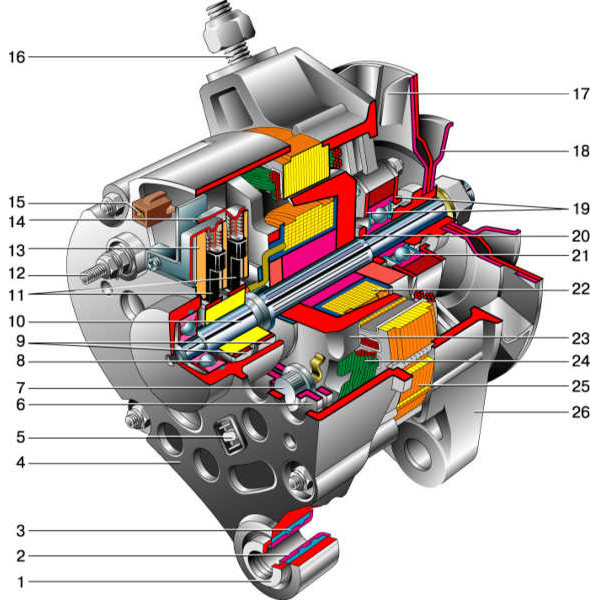
| 1 - clamping sleeve | 14 - conclusion "67" |
| 2 - bushing | 15 - neutral wire plug |
| 3 - buffer sleeve | 16 - generator mounting stud |
| 4 - back cover | 17 - fan impeller |
| 5 - screw for fixing the rectifier unit | 18 - pulley |
| 6 - rectifier unit | 19 - plates |
| 7 - valve (diode) | 20 - ring |
| 8 – rear bearing | 21 – front bearing |
| 9 - slip rings | 22 - rotor winding |
| 10 - rotor shaft | 23 - rotor |
| 11 - brushes | 24 - stator winding |
| 12 - conclusion "30" | 25 - stator |
| 13 - brush holder | 26 - front cover |

| 1 - casing | 17 - pulley |
| 2 - output "B +" for connecting consumers | 18 - nut |
| 3 - interference suppression capacitor 2.2 μF | 19 - rotor shaft |
| 4 - common output of additional diodes (connected to the "D +" output of the voltage regulator) | 20 - front bearing of the rotor shaft |
| 5 - holder of positive diodes of the rectifier unit | 21 - beak-shaped pole pieces of the rotor |
| 6 - holder of negative diodes of the rectifier unit | 22 - rotor winding |
| 7 - conclusions of the stator winding | 23 - bushing |
| 8 - voltage regulator | 24 - clamping screw |
| 9 - brush holder | 25 - rear rotor bearing |
| 10 - back cover | 26 - bearing sleeve |
| 11 - front cover | 27 - slip rings |
| 12 - stator core | 28 - negative diode |
| 13 - stator winding | 29 - positive diode |
| 14 - distance ring | 30 - additional diode |
| 15 - washer | 31 - terminal "D" (common output of additional diodes) |
| 16 - conical washer |

1 - generator; 2 - negative diode; 3 - additional diode; 4 - positive diode; 5 - control lamp for battery discharge; 6 - instrument cluster; 7 - voltmeter; 8 - mounting block; 9 - additional resistors of 100 Ohm, 2 W; 10 - ignition relay; 11 - ignition switch; 12 - storage battery; 13 - capacitor; 14 - rotor winding; 15 - voltage regulator
The main task of the rotor - create a rotating magnetic field, for this purpose the excitation winding is located on the rotor shaft. It fits in two halves of the pole, each pole half has six protrusions - these are called beaks. There are also slip rings on the shaft, there are two of them, and it is through them that the excitation winding is powered. Rings, most often, are made of copper, steel or brass rings are quite rare. The excitation winding leads are soldered directly to the rings.
One or two fan impellers are located on the rotor shaft (their number depends on the design) and a driven drive pulley is fixed. Two maintenance-free ball bearings form the rotor bearing assembly. On the side of the slip rings, a roller bearing can also be located on the shaft.
The stator is necessary to create an alternating electric current, combines a metal core and windings, the core is made up of plates, they are made of steel. It has 36 slots for winding windings, windings are laid in these slots, there are three of them, they form a three-phase connection. There are two ways to lay the windings in the grooves - wave method and loop. The windings are interconnected according to the "star" and "delta" schemes.
What are these schemes?
- "Star" - some ends of the windings are connected at one point, and the other ends are leads;
- "Triangle" - a circular connection of the ends of the windings in sequence, the conclusions come from the connection points.
The brush unit serves to ensure the transfer of the excitation current to the contact rings. It consists of two graphite brushes, springs that press them, and a brush holder. In generators modern machines the brush holder is located with a voltage regulator in a single non-separable unit.
The rectifier unit performs the function of converting the sinusoidal voltage, which is generated by the generator, into the DC voltage of the vehicle's on-board network. These are plates that act as heat sinks with mounted diodes. The unit contains six power semiconductor diodes, for each phase there are two diodes, one for the "positive" and the other for the "negative" output of the generator.
On many generators, the field winding is connected through a separate group, which consists of two diodes. These rectifiers prevent the discharge of the battery discharge current through the winding when the engine is not running. When the windings are connected according to the "star" principle, two additional power diodes are installed at the zero terminal, allowing the generator power to be increased by up to 15 percent. The rectifier unit is turned off into the generator circuit at special mounting sites by soldering, welding, or bolting.
Voltage regulator - its purpose is to maintain the generator voltage within certain limits. Currently, generators are equipped with semiconductor electronic (or integral) voltage regulators.
Voltage regulator designs:
- hybrid design - the use of radio elements and electronic devices at electronic circuit together;
- integral design - all components of the regulator (excluding the output stage) are made using thin-film microelectronic technology.
The voltage regulator changes the voltage supplied to charge the storage battery by temperature compensation of the voltage (depending on air temperature). The higher the air temperature, the less voltage goes to the battery.
The generator is driven by a belt drive; it rotates the rotor at a speed two to three times higher than the crankshaft speed. In different designs of the generator, a poly-V or V-belt can be used:
- V-belt has the prerequisites for rapid wear, (this depends on the specific pulley diameter), since the field of application of the V-belt is limited by the dimensions of the driven pulley.
- V-ribbed belt is considered more universal, applicable for small diameters of the driven pulley, with its help, more ratio. Modern models generators have a poly V-belt in their designs.

When the key is turned in the ignition lock, current flows to the field winding through the brush assembly and slip rings. A magnetic field is induced in the winding. The generator rotor begins to move with the rotation of the crankshaft. The stator windings are penetrated by the rotor's magnetic field. An alternating voltage occurs at the terminals of the stator windings. Upon reaching a certain speed, the excitation winding is powered directly from the generator, that is, the generator goes into self-excitation mode.
The AC voltage is converted by the rectifier unit to DC. In this state, the generator is engaged in providing the required current to charge the power supply to consumers and the battery.
The voltage regulator turns on when the load and the crankshaft speed change. He is engaged in adjusting the turn-on time of the excitation winding. The time to turn on the field winding decreases with a decrease in the external load and an increase in the generator speed. The time increases with increasing load and decreasing speed. When the consumed current exceeds the capabilities of the generator, the battery is switched on. There is a warning lamp on the dashboard that monitors the operating condition of the generator.
The main parameters of the generator:
- rated voltage;
- rated excitation frequency;
- rated current;
- self-excitation frequency;
- Efficiency (coefficient of performance).
Current-speed characteristic Is the dependence of the current strength on the generator rotation frequency.
In addition to the nominal values, the current-speed characteristic has other points:
- minimum current and minimum operating speed (40-50% of the rated current is the minimum current);
- maximum current and maximum speed (no more than 10% maximum current exceeds the nominal).
Video
The main source of current in the car is the generator. Without a working generator, the car will not go far. In the event of a generator malfunction, the battery is not sufficiently charged, which leads to a gradual de-energization of electrical appliances and further leads to the impossibility of continuing to move.
Therefore, it is so important for car enthusiasts to maintain the performance of one of the key components of the car.
Generator malfunctions can manifest themselves most different ways, but most often you should pay attention to the generator in the event that any noise comes from the generator, or if you often notice an insufficient battery charge or complete absence such.
This can be seen very simply. The car did not start, you started it by lighting a cigarette from another car. We went somewhere, the engine was turned off, and then again you cannot start the car, the starter does not turn. That is, either the battery has served its purpose, or the generator does not charge it.
Diagnostics of mechanical breakdowns of the generator
Here, in general, everything is simple. If it makes a noise, squeals, whistles, rattles, howls, then the matter is either in the bearings, which must be checked for lubrication and wear. Sometimes it is enough to add lubricant and the noise disappears. In more serious cases, the bearings must be replaced with new ones.

In addition to bearings, noise and howling can appear in the case of turn-to-turn short circuits of the windings of either the stator or the traction relay. Also, the cause of an unpleasant sound can be a short circuit of the windings on the case, bad contacts. That is, it is obvious that the sound appears in the case of mechanical interaction of any parts of the generator during its operation. All this can be identified by visual inspection of the generator. Where contact occurs, traces of this contact are likely to be visible.
Having found a breakdown, you should assess the degree of its seriousness, the possibility of repair. But mechanical faults, this is not the only thing that can disrupt the operation of the generator.
Checking the voltage of the car generator
In order to establish the generator's operability, its output voltage should be checked, and then the main causes of malfunctions should be diagnosed. To measure voltage, a voltmeter is most often used, which is connected to the poles of a battery, less often an ohmmeter or multimeter.
When starting the engine, the voltage at the motor terminals should not exceed 8 V. The procedure is best carried out not on a cold engine and the ambient temperature is not lower than 20 degrees Celsius.
For the further continuation of the experiment, you need to "turn on the gas", thus increasing the engine speed. This must be done until the tachometer needle shows 3000 rpm. Then you should make another measurement of the voltage at the terminals of the battery. If the indicator is less than 12.5 V, it's time to start repairing the generator.
Dismantling of the faulty generator is necessary by disconnecting the ground terminal from the battery. Then, using a screwdriver, you must disconnect the voltage regulator mount.
Before proceeding to a more detailed diagnosis, it is necessary to perform an external inspection of the generator, namely, to check the wear of the brushes and slip rings and, if soot is present, to grind.
Most common reason a malfunction of the generator is a malfunction of the voltage regulator, so it is better to change it periodically before the expiration date of the part.
The generator is installed in its original position in reverse order, at the end, the mass is carefully connected to the battery.
After completing these simple steps, you need to reconnect the voltmeter to the battery poles. When starting the engine and raising the engine speed to a value of 3000 rpm, the gauge should show a voltage value in the range of 13.5-14.5 V. Such a voltmeter value will mean that the cause of the problem has been eliminated.
Voltage stabilization check
The next step is to check the voltage stabilization. It is carried out as follows. With headlights on high beam car using a voltmeter, we make the necessary voltage measurements. If the obtained indicator does not differ by more than 0.4 V from the previously measured one, then everything is in order.
The method described above for checking a car generator is simple and straightforward and requires only the presence measuring instrument, basic skills of an automobile master and a desire to independently figure out the reasons for the malfunction of the iron horse.
Checking the vehicle power supply circuit
With the help of a measuring device, we will be able to check the car's power supply circuit.
To check the diode bridge, it is necessary to connect a voltmeter to the generator terminal and "ground". The likelihood of a diode malfunction will be obvious when the voltage is above 0.5 V.
To determine the breakdown of diodes, connect the device between terminal "30" and the disconnected wire of the generator. A discharge current reading of less than 5 mA will be acceptable.
To check the voltage regulator, you will first need to warm up the engine at medium speed with the lights on for at least 15 minutes. Next, using a voltmeter, you need to measure the voltage on one side at the "mass" and on the other - at the terminal "30". Voltmeter readings for different cars may differ.
If necessary, you can check the regulated voltage. To do this, you must connect the measuring device to the battery. With such a check, it is necessary that the revolutions are close to maximum, and all energy consumers are turned on. The value obtained during the measurement will be individual, depending on the vehicle modification.
An ohmmeter and a multimeter are used to diagnose the resistance in the field winding. First of all, the voltage regulator and the brush holder are removed. Next, you need to make sure that the winding is intact and clean the slip rings. When checking the resistance, the test leads of the measuring device must be applied to the slip rings. A normal reading will be 5-10 ohms.
A multimeter must be used to check for a short to ground. One probe of the device must be attached to the stator of the generator, the other must be connected to the slip ring. If the winding does not short to ground, the multimeter will show infinitely high resistance.
It is possible to eliminate small malfunctions on your own, however, it should be remembered that for a more thorough diagnosis, complex measurements and subsequent repair of the generator, you need to contact certified services.
AUTOMOTIVE GENERATORS
The electrical equipment of any car includes a generator - the main source of electricity. Together with the voltage regulator, it is called a generator set. On modern cars alternators are installed. They meet the requirements to the greatest extent.
Basic requirements for car generators
1. The generator must provide an uninterrupted supply of current and have sufficient power to:
- simultaneously supply electricity to working consumers and charge the battery;
- when all regular consumers of electricity were turned on at low engine speeds, a strong discharge of the battery did not occur;
- the voltage in the on-board network was within the specified limits over the entire range of electrical loads and rotor speeds.
2. The generator must have sufficient strength, long service life, small weight and dimensions, low noise and radio interference.
Basic concepts
Domestic developers and manufacturers of electrical equipment use the following concepts.
Vehicle power supply system - intended for uninterruptible power supply electrical appliances included in the vehicle electrical system. Consists of a generator set, a battery and devices that monitor the performance and protect the system from overloads.
Generator - a device that converts mechanical energy received from the engine into electrical energy.
Voltage regulator - a device that maintains the voltage of the vehicle's on-board network within the specified limits when changing the electrical load, generator rotor speed and ambient temperature.
Rechargeable starter battery (battery) - accumulates and stores electricity for starting the engine and powering electrical appliances for a short time (when the engine is not running or insufficient power developed by the generator).
The principle of the generator.
The generator is based on the effect of electromagnetic induction. If a coil, for example, made of a copper wire, is penetrated by a magnetic flux, then when it changes, an alternating electric voltage appears at the terminals of the coil. Conversely, for the formation of a magnetic flux, it is enough to pass an electric current through the coil. Thus, to obtain alternating electric current, a coil is required through which a direct electric current flows, forming a magnetic flux, called a field winding, and a steel pole system, the purpose of which is to bring the magnetic flux to coils called a stator winding, in which an alternating voltage is induced. These coils are placed in the grooves of the steel structure, the magnetic core (iron package) of the stator. The stator winding with its magnetic circuit forms the generator stator itself, its most important stationary part, in which an electric current is generated, and the excitation winding with a pole system and some other parts (shaft, slip rings) - the rotor, its most important rotating part. The excitation winding can be powered from the generator itself. In this case, the generator is self-excited. In this case, the residual magnetic flux in the generator, that is, the flux that is formed by the steel parts of the magnetic circuit in the absence of current in the excitation winding, is small and provides self-excitation of the generator only at too high speeds. Therefore, such an external connection is introduced into the generator set circuit, where the field windings are not connected to the storage battery, usually through a lamp for monitoring the operating state of the generator set. The current flowing through this lamp into the field winding after the ignition switch is turned on provides the initial excitation of the generator. The strength of this current should not be too large so as not to discharge the battery, but not too small, since in this case the generator is excited at too high speeds, therefore the manufacturers specify the required power of the test lamp - usually 2 .. .3 Tue
When the rotor rotates opposite the coils of the stator winding, the "north" and "south" poles of the rotor appear alternately, that is, the direction of the magnetic flux penetrating the coil changes, which causes an alternating voltage to appear in it. The frequency of this voltage f depends on the rotor speed of the generator N and the number of its pole pairs p:
f \u003d p * N / 60
With rare exceptions, generators of foreign firms, as well as domestic ones, have six "south" and six "north" poles in the rotor magnetic system. In this case, the frequency f is 10 times less than the rotation frequency of the generator rotor. Since the rotor of the generator receives its rotation from the crankshaft of the engine, the frequency of rotation of the crankshaft of the engine can be measured by the frequency of the alternating voltage of the generator. To do this, a stator winding is drawn from the generator, to which a tachometer is connected. In this case, the voltage at the input of the tachometer has a pulsating character, since it turns out to be connected in parallel to the diode of the generator's power rectifier. Taking into account the gear ratio i of the belt drive from the engine to the generator, the frequency of the signal at the input of the tachometer f t is related to the rotational speed of the engine crankshaft N two by the ratio:
f \u003d p * N dv (i) / 60
Of course, if the drive belt slips, this ratio is slightly disturbed and therefore care should be taken to ensure that the belt is always sufficiently tensioned. When p \u003d 6, (in most cases) the above ratio is simplified f t \u003d N dv (i) / 10. The on-board network requires a constant voltage supply to it. Therefore, the stator winding feeds the vehicle's on-board network through a rectifier built into the generator.
The stator winding of generators of foreign companies, as well as domestic ones, is three-phase. It consists of three parts, called phase windings or simply phases, in which the voltage and currents are displaced relative to each other by a third of the period, i.e., by 120 electrical degrees, as shown in Fig. I. The phases can be connected in a "star" or "triangle". At the same time, phase and line voltages and currents are distinguished. Phase voltages U f act between the ends of the phase windings. I currents I f flow in these windings, while the line voltages U l act between the wires connecting the stator winding with the rectifier. Linear currents J l flow in these wires. Naturally, the rectifier straightens those quantities that are supplied to it, that is, linear ones.
Fig. 1. Schematic diagram generator set.U f1 - U f3 - voltage in the phase windings: U d - rectified voltage; 1, 2, 3 - windings of three stator phases: 4 - power rectifier diodes; 5 - storage battery; 6 - load; 7 - diodes of the excitation winding rectifier; 8 - excitation winding; 9 - voltage regulator
When connected in a "triangle", the phase currents at the root are 3 times less than linear currents, while in the "star" the linear and phase currents are equal. This means that with the same current given by the generator, the current in the phase windings, when connected in a "triangle", is much less than that of a "star". Therefore, in generators of high power, a "triangle" connection is often used, since at lower currents the windings can be wound with a thinner wire, which is more technologically advanced. However, the line voltages at the "star" at the root of 3 are greater than the phase voltages, while at the "triangle" they are equal and to obtain the same output voltage, at the same rotational speeds, the "triangle" requires a corresponding increase in the number of turns of its phases in comparison with "star".
Thinner wire can also be used for star connections. In this case, the winding is made of two parallel windings, each of which is connected in a "star", that is, a "double star" is obtained.
The rectifier for a three-phase system contains six power semiconductor diodes, three of which: VD1, VD3 and VD5 are connected to the "+" terminal of the generator, and the other three: VD2, VD4 and VD6 with a "-" ("ground") terminal. If it is necessary to boost the generator power, an additional rectifier arm is used on the VD7, VD8 diodes, shown in Fig. 1, with a dotted line. Such a rectifier circuit can take place only when the stator windings are connected to a "star", since the additional arm is powered from the "zero" point of the "star".
In a significant number of types of generators of foreign companies, the field winding is connected to its own rectifier, assembled on VD9-VD 11 diodes. This connection of the field winding prevents the discharge current of the battery from flowing through it when the car engine is not running. Semiconductor diodes are in the open state and do not offer significant resistance to the passage of current when a voltage is applied to them forward direction and practically do not pass current at reverse voltage. From the phase voltage graph (see Fig. 1), you can determine which diodes are open and which are closed at the moment. Phase voltages U f1 acts in the winding of the first phase, U f2 - the second, U f3 - the third. These voltages change along curves close to a sinusoid and at some moments of time they are positive, at others they are negative. If the positive direction of the voltage in the phase is taken along the arrow directed to the zero point of the stator winding, and negative from it, then, for example, for the moment t 1, when the voltage of the second phase is absent, the first phase is positive, and the third is negative. The direction of the phase voltages corresponds to the arrows shown in Fig. 1. The current through the windings, diodes and the load will flow in the direction of these arrows. In this case, the diodes VD1 and VD4 are open. Having considered any other points in time, it is easy to make sure that in a three-phase system the voltage arising in the windings of the generator phases, the diodes of the power rectifier go from open to closed and back in such a way that the current in the load has only one direction - from the "+" terminal of the generator set to its conclusion "-" ("mass"), that is, a constant (rectified) current flows in the load. The rectifier diodes of the field winding work in the same way, supplying this winding with a rectified current. Moreover, the excitation winding rectifier also includes 6 diodes, but three of them VD2, VD4, VD6 are common with the power rectifier. So at time t 1 diodes VD4 and VD9 are open, through which the rectified current flows into the excitation winding. This current is significantly less than the current supplied by the generator to the load. Therefore, as VD9-VD11 diodes, small-sized low-current diodes for a current of no more than 2 A are used (for comparison, the diodes of a power rectifier allow currents to flow up to 25 ... 35 A).
It remains to consider the principle of operation of the rectifier arm containing diodes VD7 and VD8. If the phase voltages changed purely in a sinusoidal manner, these diodes would not participate at all in the process of converting alternating current to direct current. However, in real generators, the shape of the phase voltages differs from the sinusoid. It is the sum of sinusoids, which are called harmonic components or harmonics - the first, the frequency of which coincides with the frequency of the phase voltage, and the highest, mainly the third, the frequency of which is three times higher than the first. The representation of the real form of the phase voltage in the form of the sum of two harmonics (first and third) is shown in Fig. 2. It is known from electrical engineering that in the line voltage, that is, in the voltage that is supplied to the rectifier and rectified, the third harmonic is absent. This is due to the fact that the third harmonics of all phase 
Fig. 2. Representation of phase voltage U f as the sum of sinusoids of the first, U 1, and third U 3, harmonics
voltages coincide in phase, that is, they simultaneously reach the same values \u200b\u200band at the same time mutually balance and cancel each other in line voltage. Thus, the third harmonic is present in the phase voltage, but not in the linear voltage. Consequently, the power developed by the third harmonic of the phase voltage cannot be used by consumers. To use this power, diodes VD7 and VD8 are added, connected to the zero point of the phase windings, that is, to the point where the action of the phase voltage affects. Thus, these diodes only rectify the voltage of the third harmonic of the phase voltage. The use of these diodes increases the generator power by 5 ... 15% at a speed of more than 3000 min-1.The rectified voltage, as shown in Fig. 1, has a pulsating character. This ripple can be used to diagnose the rectifier. If the ripples are identical, the rectifier is working normally, if the picture on the oscilloscope screen has a violation of symmetry, the diode may fail. This check should be done with the battery disconnected. It should be noted that the term "rectifier diode" does not always hide the usual design, which has a housing, leads, etc. sometimes it is just a semiconductor silicon junction sealed on the heat sink.
The use of electronics and especially microelectronics in the voltage regulator, that is, the use of field-effect transistors or the implementation of the entire voltage regulator circuit on a silicon single crystal, required the introduction of protection elements into the generator set against high voltage surges that occur, for example, when a battery is suddenly disconnected, load shedding. Such protection is provided by the fact that the diodes of the power bridge are replaced by zener diodes. The difference between a zener diode and a rectifier diode is that when a voltage is applied to it in the opposite direction, it does not pass current only up to a certain value of this voltage, called the stabilization voltage. Usually in power zener diodes, the stabilization voltage is 25 ... 30 V. When this voltage is reached, the zener diodes "break through", that is, they begin to pass current in the opposite direction, and within certain limits of the change in the strength of this current, the voltage on the zener diode, and, consequently, and at the output "+" of the generator remains unchanged, not reaching dangerous values \u200b\u200bfor electronic components. The property of a zener diode to maintain a constant voltage at its terminals after "breakdown" is also used in voltage regulators.
Generator device
According to their design, the generator sets can be divided into two groups - generators of traditional design with a fan at the drive pulley and generators of the so-called compact design with two fans in the inner cavity of the generator. Usually "compact" generators are equipped with a drive with a higher gear ratio through a poly-V-belt and therefore, according to the terminology accepted by some companies, are called high-speed generators. At the same time, within these groups, generators can be distinguished, in which the brush assembly is located in the inner cavity of the generator between the pole system of the rotor and the rear cover, and generators, where the slip rings and brushes are located outside the inner cavity. In this case, the generator has a casing, under which there is a brush assembly, a rectifier and, as a rule, a voltage regulator.
Any generator contains a stator with a winding, sandwiched between two covers - the front, from the drive side, and the rear, from the slip rings. The covers, cast from aluminum alloys, have ventilation windows through which air is blown by a fan through the generator.
Generators of traditional design are equipped with ventilation windows only in the end part, generators of "compact" design are also on the cylindrical part above the frontal sides of the stator winding. The "compact" design is also distinguished by highly developed ribbing, especially in the cylindrical part of the covers. A brush assembly, which is often combined with a voltage regulator, and a rectifier assembly are attached to the cover on the side of the slip rings. The covers are usually tightened together with three or four screws, with the stator usually clamped between the covers, the seating surfaces of which cover the stator along the outer surface. Sometimes the stator is completely recessed into the front cover and does not rest against the back cover, there are designs in which the middle sheets of the stator package protrude above the rest and they are the seat for the covers. The mounting legs and tensioning ear of the generator are cast together with the covers, and if the fastening is two-legged, then the paws have both covers, if it is one-legged, only the front one. However, there are designs in which one-leg fastening is carried out by joining the tides of the rear and front covers, as well as two-leg fasteners, in which one of the legs, made of stamping from steel, is screwed to the back cover, as, for example, in some generators of the Paris-Rhone company of the previous issues. In the case of a two-leg mounting, a spacer sleeve is usually located in the hole of the rear leg, which allows you to choose the gap between the engine bracket and the foot seat when installing the generator. The hole in the tension ear can be one with or without a thread, but there are also several holes, which makes it possible to install this generator on different brands engines. For the same purpose, two pull ears are used on one generator.

Fig. 31 - core, 2 - winding, 3 - groove wedge, 4 - groove, 5 - output for connection with a rectifier
The generator stator (Fig. 3) is assembled from steel sheets 0.8 ... 1 mm thick, but more often it is wound "on the edge". This design provides less waste during processing and high manufacturability. When performing a stator package by winding, the stator yoke above the grooves usually has protrusions along which the position of the layers relative to each other is fixed during winding. These protrusions improve the cooling of the stator due to its more developed outer surface. The need to save metal also led to the creation of a stator package made of individual horseshoe-shaped segments. The individual sheets of the stator package are fastened together into a monolithic structure by welding or rivets. Almost all generators of mass production cars have 36 slots in which the stator winding is located. The grooves are insulated with foil or epoxy coating.

Fig. 4A - distributed loop, B - concentrated wave, C - distributed wave
------- 1 phase, - - - - - - 2 phase, -..-..-..- 3 phase
In the grooves there is a stator winding, made according to the schemes (Fig. 4) in the form of a loop distributed (Fig. 4, A) or wave concentrated (Fig. 4, B), wave distributed (Fig. 4, C) windings. The loop winding differs in that its sections (or half-sections) are made in the form of coils with frontal connections on both sides of the stator package opposite each other. The wave winding really resembles a wave, since its frontal connections between the sides of the section (or half-section) are alternately located on one or the other side of the stator package. In a distributed winding, the section is divided into two half-sections, emanating from one slot, with one half-section extending to the left, the other to the right. The distance between the sides of the section (or half-section) of each phase winding is 3 slot divisions, i.e. if one side of the section lies in the groove conventionally taken as the first, then the second side fits into the fourth groove. The winding is fixed in the groove with a groove wedge made of insulating material. It is obligatory to impregnate the stator with varnish after laying the winding.
A feature of automobile generators is the type of the rotor pole system (Fig. 5). It contains two pole halves with projections - beak-shaped poles, six on each half. Pole halves are made by stamping and may have protrusions - half bushings. In the absence of protrusions when pressing onto the shaft between the pole halves, a bushing with an excitation winding wound on the frame is installed, and the winding is carried out after the bushing is installed inside the frame.

Fig. 5. Automotive generator rotor: a - assembled; b - disassembled pole system; 1.3-pole halves; 2 - excitation winding; 4 - slip rings; 5 - shaft
If the pole halves have half bushings, then the excitation winding is pre-wound on the frame and installed when the pole halves are pressed in so that the half bushings enter the frame. The end cheeks of the frame have lugs-retainers that enter the inter-pole gaps at the ends of the pole halves and prevent the frame from turning on the bushing. Pressing the pole halves onto the shaft is accompanied by their stamping, which reduces the air gaps between the bushing and the pole halves or half bushings, and has a positive effect on the output characteristics of the generator. When stamping, the metal flows into the grooves of the shaft, which makes it difficult to rewind the excitation winding when it burns out or breaks, since the pole system of the rotor becomes difficult to disassemble. The excitation winding complete with the rotor is impregnated with varnish. Pole beaks at the edges are usually beveled on one or both sides to reduce the magnetic noise of the generators. In some designs, for the same purpose, an anti-noise non-magnetic ring is placed under the sharp cones of the beaks, located above the excitation winding. This ring prevents the beaks from vibrating when the magnetic flux changes and, consequently, the emission of magnetic noise by them.
The brush assembly is a plastic structure that houses the brushes i.e. sliding contacts. In automobile generators, two types of brushes are used - copper-graphite and electro-graphite. The latter have an increased voltage drop in contact with the ring in comparison with copper-graphite, which adversely affects the output characteristics of the generator, but they provide significantly less wear of the slip rings. The brushes are pressed against the rings by the force of the springs. Usually brushes are installed along the radius of the slip rings, but there are also so-called reactive brush holders, where the axis of the brushes forms an angle with the radius of the ring at the point of contact of the brush. This reduces the friction of the brush in the guides of the brush holder and thus ensures more reliable contact of the brush with the ring. Often the brush holder and voltage regulator form a non-separable single unit.
Rectifier units are used of two types - either they are heat sink plates into which the diodes of the power rectifier are pressed (or soldered) or on which the silicon junctions of these diodes are soldered and sealed, or these are structures with highly developed fins, in which diodes, usually of the tablet type, are soldered to the heat sinks. The diodes of the additional rectifier usually have a plastic housing of a cylindrical shape or in the form of a pea, or they are made in the form of a separate sealed unit, the connection of which is carried out into the circuit with bars. The rectifier units are connected to the generator circuit by unsoldering or welding the phase leads on special mounting pads of the rectifier or with screws. The most dangerous for the generator and especially for the wiring of the automobile on-board network is the jumpering of the heat sink plates connected to the "ground" and the "+" terminal of the generator by accidentally falling between them metal objects or conductive bridges formed by pollution, because in this case, a short circuit occurs in the battery circuit and a fire is possible. To avoid this, the plates and other parts of the rectifier of some manufacturers' generators partially or completely cover insulating layer... In the monolithic structure of the rectifier unit, the heat sinks are united mainly by circuit boards made of insulating material, reinforced with connecting bars.
Bearing units generators are usually deep groove ball bearings with one-time grease for life and one or two-sided seals built into the bearing. Roller bearings are used only on the side of slip rings and are rarely used, mainly by American firms. The seating of ball bearings on the shaft from the side of the slip rings is usually tight, from the drive side - sliding, in seat the covers, on the contrary - from the side of the slip rings - sliding, from the side of the drive - tight. Since the outer cage of the bearing from the side of the slip rings has the ability to rotate in the seat of the cover, the bearing and cover may soon fail, and the rotor will rub against the stator. To prevent the bearing from rotating, various devices are placed in the cover seat - rubber rings, plastic cups, corrugated steel springs, etc.

Fig. 6. Voltage regulators from Bosch in various designs.
a - on discrete elements; b - hybrid installation; c - a diagram on a silicon single crystal.
1 - power output stage, 2 - control circuit
The design of voltage regulators is largely determined by their manufacturing technology. When making a circuit with discrete elements, the regulator usually has a printed circuit board on which these elements are located. In this case, some elements, for example, tuning resistors, can be made using thick-film technology. Hybrid technology assumes that resistors are made on a ceramic plate and are connected to semiconductor elements - diodes, zener diodes, transistors, which are soldered on a metal substrate in an unpackaged or case design. In a regulator made on a single crystal of silicon, the entire regulator circuit is located in this crystal. Figure 6 shows the evolution of Bosch voltage regulators, including all of the above designs. Hybrid voltage regulators and monocrystal voltage regulators cannot be disassembled or repaired.
The generator is cooled by one or two fans mounted on its shaft. At the same time, in the traditional design of generators (Fig. 7, a), air is sucked by a centrifugal fan into the cover from the side of the slip rings. In generators with a brush assembly, a voltage regulator and a rectifier outside the inner cavity and protected by a casing, air is sucked through the slots of this casing, directing the air to the most heated places - to the rectifier and voltage regulator. On cars with a dense layout of the engine compartment, in which the air temperature is too high, generators with a special casing (Fig. 7, b) are used, fixed on the rear cover and equipped with a pipe with a hose through which cold and clean outside air enters the generator. Such constructions are used, for example, on bMW cars... For generators of a "compact" design, cooling air is drawn in from both the rear and front covers.
Fig. 7. Generator cooling system.
a - generators of conventional design; b - generators for elevated temperatures in the engine compartment; c - generators of compact design.
Arrows show the direction of air flows
Generating set characteristics
The ability of a generator set to provide consumers with electricity at various operating modes of the engine is determined by its current-speed characteristic (TCX) - the dependence of the maximum current given by the generator on the rotor speed at a constant voltage on the power terminals. In fig. 1 shows the current-speed characteristic of the generator.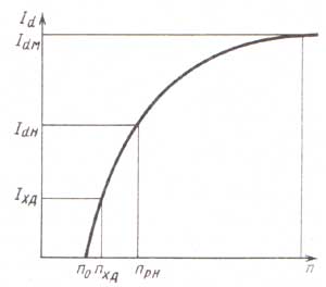
Figure: 1. Current-speed characteristic of generating sets.
The graph has the following characteristic points:
n 0 - initial rotor speed without load, at which the generator starts to deliver current;
I xd - generator recoil current at a speed corresponding to the minimum stable idle speed of the engine. On modern generators, the current delivered in this mode is 40-50% of the nominal;
I dm - maximum (rated) recoil current at a rotor speed of 5000 min "" (6000 min "" for modern generators).
Distinguish TLC, defined:
The technical documentation for generators often does not indicate the entire TLC,
- with self-excitation (the excitation winding circuit is powered by its own generator);
- with independent excitation (the excitation winding circuit is powered from an external source);
- for a generator set (voltage regulator is included in the circuit);
- for a generator (voltage regulator is disabled);
- in a cold state (cold is understood as a state in which the temperature of the generator nodes is practically equal to the ambient temperature (25 ± 10) ° С, since during the experimental determination of TLC the generator heats up, the experiment time should be minimal, i.e. not more than 1 min , and a repeated experiment should be carried out after the temperature of the nodes again becomes equal to the ambient temperature);
- in a heated state.
but only its individual characteristic points (see Fig. 1).
These points include:
How to determine the parameters of your generator:
- initial speed at idle n 0. It corresponds to the generator set voltage without load;
- the highest current delivered by the generator I dm. (Automotive valve generators are self-limiting, that is, having reached a force I dm, the value of which is close to the value of the short-circuit current, the generator, with a further increase in the speed of rotation, cannot give more current to consumers. The current I dm multiplied by the rated voltage determines the rated power automobile generators);
- rotation frequency n pn and current I dn in the design mode. (The point of the design mode is determined at the point where the TCX touches the tangent drawn from the origin. The approximate calculated value of the current strength can be determined as 0.67 I dm The design mode corresponds to the maximum mechanical moment of the generator and in the region of this mode the largest heating of the nodes is observed, since with an increase in the rotational speed increases the generator current and, consequently, the heating of its nodes, but at the same time the intensity of the generator cooling by a fan located on its shaft also increases.
- rotational speed n xd and current I xd in a mode corresponding to idling of an internal combustion engine (ICE). In this mode, the generator must deliver the amperage required to power a number of the most important consumers, primarily ignition in carburetor ICEs.
For domestic generators: On new models of domestic engines (VAZ-2111, 2112, ZMZ-406, etc.): generators of compact design are installed (94.3701, etc.). Brushless (inductor) generators (955.3701 for VAZ, G700A for UAZ) differ from the traditional design in that they have permanent magnets on the rotor, and the field windings are on the stator (mixed excitation). This made it possible to do without the brush assembly (the vulnerable part of the generator) and slip rings. However, these generators have a slightly higher mass and a higher noise level.
The generator's panel usually indicates its main parameters:
- rated voltage 14 or 28 V (depending on the rated voltage of the electrical system);
- rated current, which is taken as the maximum output current of the generator.
- Type, brand of generator
The main characteristic of a generator set is its current-speed characteristic (TLC), that is, the dependence of the current given by the generator to the network on the speed of its rotor at a constant voltage on the generator's power terminals.
This characteristic is determined when the generator set is running complete with a fully charged storage battery with a nominal capacity expressed in A / h, which is not less than 50% of the nominal current of the generator. The characteristic can be determined in cold and hot states of the generator. In this case, the cold state is understood as one in which the temperature of all parts and components of the generator is equal to the ambient temperature, the value of which should be 23 ± 5 ° C. The air temperature is determined at a point 5 cm from the generator air intake. Since the generator heats up during characterization due to the power losses released in it, it is methodically difficult to remove the TLC in a cold state, and most firms give the current-speed characteristics of generators in a heated state, i.e., in a state in which the components and components of the generator are heated in each determined point to a steady-state value due to the power losses released in the generator at the above-mentioned cooling air temperature.
The range of speed variation when taking the characteristic is between the minimum frequency at which the generator set develops a current of 2A (about 1000 min -1) and the maximum. The characteristic is taken with an interval of 500 to 4000 min -1 and 1000 min -1 at higher frequencies. Some companies give the current-speed characteristics determined at the rated voltage, i.e. at 14 V, typical for cars. However, it is possible to remove such characteristics only with a regulator specially reconstructed to a high voltage maintenance level. To prevent the voltage regulator from working when the current-speed characteristic is taken, it is determined at voltages U t \u003d 13.5 ± 0.1 V for a 12-volt on-board system. An accelerated method for determining the current-speed characteristic is also allowed, requiring a special automated stand, in which the generator warms up for 30 minutes at a rotational speed of 3000 min -1 corresponding to this frequency, current strength and the above voltage. The time to take the characteristic should not exceed 30 s with a constantly changing speed.
The current-speed characteristic has characteristic points, which include:
n 0 - initial speed without load. Since usually the characterization begins with the load current (about 2A, this point is obtained by extrapolating the measured characteristic to the intersection with the abscissa axis.
n L is the minimum operating speed, i.e. the speed approximately corresponding to the idle speed of the engine. It is conventionally accepted, n L \u003d 1500 min -1. The current I L corresponds to this frequency. Firm Bosch for "compact" generators adopted n L \u003d 1800 min -1. Typically I L is 40 ... 50% of the rated current.
n R is the rated speed at which the rated current I R is generated. This speed is taken n R \u003d 6000 min -1. I R is the smallest current that the generator set must produce at a speed n R.
N MAX - maximum speed. At this speed, the generator generates a maximum current I max. Usually, the maximum current strength differs little from the nominal I R (no more than 10%).
Manufacturers give in their information materials mainly only characteristic points of the current-speed characteristic. However, for generator sets of cars with a sufficient degree of accuracy, it is possible to determine the current-speed characteristic by the known nominal value of the current I R and the characteristic according to Fig. 8, where the generator current values \u200b\u200bare given in relation to its nominal value.
In addition to the current-speed characteristic, the generator set is also characterized by the self-excitation frequency. When the generator is running on a car, complete with a storage battery, the generator set must self-excite at an engine speed lower than its idle speed. In this case, of course, the circuit must include a lamp for monitoring the operating state of the generator set with the power specified for it by the manufacturer of the generator and resistors parallel to it, if they are provided by the circuit.
Another characteristic by which it is possible to represent the energy capacity of the generator, that is, to determine the value of the power taken by the generator from the engine, is the value of its efficiency, determined in the modes corresponding to the points of the current-speed characteristic (Fig. 8), the value of the efficiency by Fig. 8 is shown for orientation, because it depends on the design of the generator - the thickness of the plates from which the stator is assembled, the diameter of the slip rings, bearings, the resistance of the windings, etc., but mainly on the power of the generator. The more powerful the generator, the higher its efficiency.

Fig. 8
Output characteristics of car generators:
1 - current-speed characteristic, 2 - efficiency by points of current-speed characteristic
Finally, the generator set is characterized by the range of its output voltage, with changes within certain limits of speed, load current and temperature. Usually, the prospectuses of companies indicate the voltage between the power terminal "+" and the "mass" of the generator set at the control point or the voltage of the regulator setting when the generator set is cold at a speed of 6000 min -1, load with a current of 5 A and work complete with a battery. as well as temperature compensation - a change in the regulated voltage depending on the ambient temperature. Thermal compensation is indicated as a coefficient characterizing the voltage change when the ambient temperature changes by ~ 1 ° C. As shown above, the voltage of the generator set decreases with increasing temperature. For passenger cars, some companies offer generator sets with the following regulator setting voltage and temperature compensation:
Setting voltage, V ................................. 14.1 ± 0.1 14.5 + 0, 1
Thermal compensation, mV / ° С ............................... —7 + 1.5 —10 ± 2
Generator parameters.
The following designations are used in the table: P max - maximum power output, U nom - rated voltage, I max - maximum output current at maximum rotor speed (for most generators for maximum speed adopted 6000 rpm), N o - the initial excitation frequency of the generator (I \u003d 0), N ph - the generator speed in the design mode, I ph - the current in the design mode.Thus, knowing the initial excitation frequency and the current at this frequency, the final frequency and the maximum current, as well as one intermediate value, it is possible to construct a sufficiently accurate TLC generator at three points.
| Marking | Application |
P max, W. (U nom, V) |
N o, min -1 | I ph, A | N ph, min -1 | I max, A | Excitation |
| G502A |
ZAZ-968M LuAZ-969M |
420 (14) | 1500 | 20 | 3200 | 30 | self-excitation |
| G250 and modifications |
M412 M427 UAZ ZIL-131 ZIL-157 ZIL-130 |
500 (12) | 950 | 28 | 2100 | 40 | independent |
| G221A and modifications |
VAZ-2101 VAZ-21011 VAZ-2103 VAZ-2106 VAZ-2121 |
600 (14) | 1150 | 30 | 2500 | 42 | itself |
| G222 |
VAZ-2104 VAZ-2105 VAZ-2107 VAZ-1111 ZAZ-1102 M2141 |
700 (14) | 1250 | 35 | 2400 | 50 | itself |
| 16.3701 and modifications |
GAZ-2410 RAF-2203-01 GAZ-31029 GAZ-3102 |
900 (14) | 1100 | 45 | 2500 | 65 | itself |
| 16.3771 | UAZ | 800 (14) | 1000 | 40 | 2050 | 57 | itself |
| 17.3701 |
ZIL-425850 ZIL-157 |
500 (14) | 1000 | 24 | 2000 | 40 | independent |
| 19.3701 | 1260 (14) | 1050 | 60 | 2150 | 90 | itself | |
| 19.3771 |
GAZ-3102 GAZ-31029 GAZ-3110 |
940 (14) | 800 | 45 | 2200 | 67 | |
| 25.3771 | GAZ-3110 | 1120 (14) | 1100 | 53 | 2200 | 80 | itself |
| 26.3771 |
VAZ-2104 VAZ-2105 VAZ-2108 VAZ-2109 |
940 (14) | 800 | 45 | 2200 | 67 | |
| 29.3701 |
M2140 M412 IZH-2125 IZH-2715 |
700 (14) | 1250 | 32 | 2250 | 50 | itself |
| 32.3701 |
ZIL-130 ZIL-157 |
840 (14) | 1050 | 40 | 2200 | 60 | itself |
| 37.3701 |
VAZ-2108 VAZ-2109 VAZ-21213 M2141 |
770 (14) | 1100 | 35 | 2000 | 55 | itself |
| 38.3701 and modifications |
ZIL-4331 ZIL-133GYA |
1330 (14) | 900 | 60 | 1800 | 95 | independent |
| 45.3701 | 630 (14) | 1100 | 28 | 2000 | 45 | itself | |
| 58.3701 |
M2140 M2141 M412 IZH-2125 IZH-2715 |
730 (14) | 1400 | 32 | 2400 | 52 | itself |
| 63.3701 | BelAZ | 4200 (28) | 1500 | 150 | 2500 | 150 | itself |
| 65.3701 |
LAZ-42021 LiAZ-5256 |
2500 (28) | 1250 | 60 | 2400 | 90 | |
| 66.3701 |
PAZ-672M PAZ-3201 |
840 (14) | 1150 | 40 | 2600 | 60 | |
| 94.3701 |
GAZ-3302 VAZ-2110 |
1000 (14) | 900 | 40 | 1800 | 70 | itself |
| 851.3701 | ZIL-53012 | 1150 (14) | 1200 | 55 | 3000 | 82 | |
| 9002.3701 | ZIL-4334 | 2240 (28) | 1350 | 53 | 2600 | 80 | |
| G254 | 560 (14) | 1100 | 28 | 2350 | 40 | independent | |
| G266 and modifications | 840 (14) | 1250 | 40 | 2750 | 60 | itself | |
| G286 | 1200 (14) | 900 | 63 | 1700 | 85 | independent | |
| G273 and modifications |
KAMAZ-5320 MAZ-5335 |
780 (28) | 1100 | 20 | 2200 | 28 | independent |
| G289 and modifications | 2200 (28) | 1250 | 60 | 2400 | 80 | itself | |
| G263A, B | 4200 (28) | 1500 | 80 | 2500 | 150 | itself | |
|
955.3701 brushless |
VAZ-2108 VAZ-2109 |
900 (14) | 1050 | 50 | 2800 | 65 | itself |
| 583.3701 |
ZAZ-1102 VAZ-2108 VAZ-2109 |
740 (14) | 1400 | 40 | 2500 | 53 | itself |
Electrical diagrams of generating sets 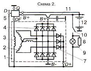
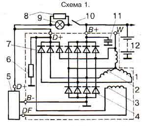
Generators drive
Fastening generators
The principle of the voltage regulator.
All gensets are now equipped with semiconductor electronic voltage regulators, usually built into the generator. The schemes of their execution and design may be different, but the principle of operation is the same for all regulators. The voltage of a generator without a regulator depends on the frequency of rotation of its rotor, the magnetic flux created by the excitation winding, and, consequently, on the strength of the current in this winding and the magnitude of the current given by the generator to consumers. The higher the rotational speed and the excitation current, the higher the generator voltage, the higher the current of its load, the lower this voltage.
The function of the voltage regulator is to stabilize the voltage when the speed and load change by acting on the excitation current. Of course, you can change the current in the excitation circuit by introducing an additional resistor into this circuit, as was done in the previous vibration voltage regulators, but this method is associated with a loss of power in this resistor and is not used in electronic regulators. Electronic controllers change the excitation current by turning on and off the excitation winding from the mains, while the relative duration of the excitation winding switching-on time changes. If, to stabilize the voltage, it is required to reduce the excitation current, the time to turn on the excitation winding decreases, if it is necessary to increase it, it increases.
It is convenient to demonstrate the principle of operation of the electronic regulator on a fairly simple diagram of the EE 14V3 type regulator from Bosch, shown in Fig. nine:
Fig. 9
BOSCH EE14V3 voltage regulator circuit:
1 - generator, 2 - voltage regulator, SA - ignition switch, HL - control lamp on the instrument panel.
To understand the operation of the circuit, you should remember that, as shown above, the Zener diode does not pass current through itself at voltages below the stabilization voltage. When the voltage reaches this value, the zener diode "breaks through" and current begins to flow through it. Thus, the Zener diode in the regulator is a voltage standard with which the generator voltage is compared. In addition, it is known that transistors pass current between the collector and the emitter, i.e. open, if the current flows in the base-emitter circuit, and this current does not pass; closed if the base current is interrupted. The voltage to the Zener diode VD2 is supplied from the output of the generator "D +" through a voltage divider across the resistors R1 (R3 and the diode VD1, which performs temperature compensation. While the voltage of the generator is low and the voltage on the Zener diode is lower than its stabilization voltage, the Zener diode is closed, through it, and, therefore, and the current does not flow in the base circuit of the transistor VT1, the transistor VT1 is also closed.In this case, the current through the resistor R6 from the "D +" terminal enters the base circuit of the transistor VT2, which opens, through its emitter-collector junction current begins to flow in the base of the transistor VT3 In this case, the excitation winding of the generator is connected to the supply circuit through the emitter-collector transition VT3.
The connection of transistors VT2 and VT3, in which their collector leads are combined, and the power supply of the base circuit of one transistor is produced from the emitter of the other, is called the Darlington circuit. With this connection, both transistors can be considered as one high gain composite transistor. Usually such a transistor is performed on a single silicon crystal. If the voltage of the generator has increased, for example, due to an increase in the frequency of rotation of its rotor, then the voltage on the Zener diode VD2 also increases, when this voltage reaches the stabilization voltage, the Zener diode VD2 "breaks through", the current through it begins to flow into the base circuit of the transistor VT1, which the emitter also opens with its transition - the collector shorts the output of the base of the composite transistor VT2, VT3 to ground. The composite transistor closes, breaking the field winding supply circuit. The excitation current decreases, the generator voltage decreases, the Zener diode VT2, the transistor VT1 close, the composite transistor VT2, VT3 opens, the excitation winding is again included in the power circuit, the generator voltage increases and the process repeats. Thus, the voltage regulation of the generator by the regulator is carried out discretely by changing the relative time of turning on the excitation winding into the power circuit. In this case, the current in the field winding changes as shown in Fig. 10. If the generator speed has increased or its load has decreased, the turn-on time of the winding decreases, if the speed has decreased or the load has increased, it increases. The regulator circuit (see Fig. 9) contains elements that are typical for the circuits of all voltage regulators used on cars. The diode VD3, when closing the composite transistor VT2, VT3, prevents dangerous voltage surges arising from an open circuit of the excitation winding with significant inductance. In this case, the field winding current can be closed through this diode and dangerous voltage surges do not occur. Therefore, the VD3 diode is called quenching. Resistance R7 is a hard feedback resistance.

Fig. 10. Change in the current strength in the excitation winding J B over time t during the operation of the voltage regulator: t on, t off - respectively, the time of switching on and off the excitation winding of the voltage regulator; n 1 n 2 - the frequency of rotation of the rotor of the generator, and n 2 is greater than n 1; J B1 and J B2 are the average values \u200b\u200bof the current in the field winding
When the composite transistor VT2, VT3 is opened, it turns out to be connected in parallel with the resistance R3 of the voltage divider, while the voltage across the Zener diode VT2 sharply decreases, this speeds up the switching of the regulator circuit and increases the frequency of this switching, which has a beneficial effect on the voltage quality of the generator set. Capacitor C1 is a kind of filter that protects the regulator from the influence of voltage pulses at its input. In general, the capacitors in the regulator circuit either prevent the transition of this circuit to an oscillatory mode and the possibility of the influence of extraneous high-frequency interference on the operation of the regulator, or accelerate the switching of transistors. In the latter case, the capacitor, being charged at one moment in time, is discharged to the base circuit of the transistor at another moment, accelerating the switching of the transistor by a burst of the discharge current and, consequently, reducing its heating and energy losses in it.
Figure 9 clearly shows the role of the HL lamp for monitoring the operating state of the generator set (charge control lamp on the vehicle dashboard). With the vehicle engine off, closing the SA ignition switch contacts allows current from the GA battery to flow through this lamp to the generator field winding. This ensures the initial excitation of the generator. At the same time, the lamp lights up, signaling that there is no break in the field winding circuit. After starting the engine, almost the same voltage appears at the generator terminals "D +" and "B +" and the lamp goes out. If the generator does not develop voltage when the car engine is running, the HL lamp continues to burn in this mode, which is a signal of a generator failure or a broken drive belt. The addition of a resistor R to the generator set enhances the diagnostic capabilities of the HL lamp. In the presence of this resistor, in the event of an open circuit in the field winding with the vehicle engine running, the HL lamp lights up. Currently, more and more companies are switching to the production of generating sets without an additional field winding rectifier. In this case, the output of the generator phase is inserted into the regulator. When the car engine is off, the voltage at the output of the generator phase is absent and the voltage regulator in this case goes into a mode that prevents the battery from discharging to the field winding. For example, when the ignition switch is turned on, the regulator circuit switches its output transistor to an oscillatory mode, in which the current in the field winding is small and amounts to a fraction of an ampere. After starting the engine, the signal from the output of the generator phase puts the regulator circuit in normal operation. In this case, the regulator circuit also controls the lamp for monitoring the operating state of the generator set.

Fig. 11. Temperature dependence of the voltage maintained by the Bosch EE14V3 regulator at a speed of 6000 min -1 and a load current of 5A.
The storage battery for its reliable operation requires that with a decrease in the temperature of the electrolyte, the voltage supplied to the battery from the generator set slightly increases, and with increasing temperature, it decreases. To automate the process of changing the level of the maintained voltage, a sensor is used, placed in the electrolyte of the storage battery and included in the voltage regulator circuit. But this is the lot of advanced cars only. In the simplest case, the temperature compensation in the regulator is selected in such a way that, depending on the temperature of the cooling air entering the generator, the voltage of the generator set changes within the specified limits. Figure 11 shows the temperature dependence of the voltage maintained by the Bosch EE14V3 regulator in one of the operating modes. The graph also shows the tolerance range for this voltage. The falling character of the dependence ensures a good charge of the battery at negative temperatures and prevents the increased boiling off of its electrolyte at high temperatures. For the same reason, on vehicles designed specifically for use in the tropics, voltage regulators are installed with a deliberately lower tuning voltage than for temperate and cold climates.
Generating set operation in different modes
When starting the engine, the main consumer of electricity is the starter, the current strength reaches hundreds of amperes, which causes a significant voltage drop at the battery terminals. In this mode, electricity consumers are powered only by the battery, which is intensively discharged. Immediately after starting the engine, the generator becomes the main source of power supply. It provides the required current to charge the battery and operate electrical appliances. After recharging the battery, the difference between its voltage and the generator becomes small, which leads to a decrease in the charging current. The generator is still the power source, and the battery smooths out the generator voltage ripple.
When powerful consumers of electricity are turned on (for example, a rear window heater, headlights, a heater fan, etc.) and a low rotor speed (low engine speed), the total consumed current may be greater than the generator is capable of delivering. In this case, the load will fall on the battery, and it will begin to discharge, which can be monitored by the readings of an additional voltage indicator or voltmeter.
Replacing the generator with a domestic analogue. General recommendations.
- generators have the same current-speed characteristics or, in terms of energy indicators, the characteristics of the replacement generator are not worse than those of the replaced one;
- the gear ratio from engine to generator is the same;
- overall and connecting dimensions of the replacement generator allow it to be installed on the engine. It should be borne in mind that most of the generators of foreign passenger cars have a one-leg mount, while domestic generators are mounted on the engine by two legs, therefore, replacing a foreign generator with a domestic one will most likely require replacing the generator mounting bracket on the engine;
- the schematics of the replacement and replacement generator set are identical.
- monitor the condition of the electrical wiring, especially the cleanliness and reliability of the connection of the contacts of the wires suitable for the generator, voltage regulator. With poor contacts, the on-board voltage may go beyond the permissible limits;
- disconnect all wires from the generator and from the battery when welding car body parts;
- make sure the alternator belt is correctly tensioned. A weakly tensioned belt does not ensure the efficient operation of the generator, a tensioned too much leads to the destruction of its bearings;
- immediately find out the cause of the alternator warning lamp coming on.
- leave the car with the battery connected if you suspect a malfunction of the generator rectifier. This can lead to a complete discharge of the battery and even fire the electrical wiring;
- check the generator's performance by shorting its terminals to ground and to each other;
- check the generator's serviceability by disconnecting the battery while the engine is running due to the possibility of failure of the voltage regulator, electronic elements of injection systems, ignition, on-board computer, etc .;
- allow contact with the electrolyte generator, "Tosola", etc.
Generator designs
According to their design, the generator sets can be divided into two groups - generators of traditional design with a fan at the drive pulley and generators of the so-called compact design with two fans in the inner cavity of the generator. Usually "compact" generators are equipped with a drive with a higher gear ratio through a poly-V-belt and therefore, according to the terminology accepted by some companies, are called high-speed generators. At the same time, within these groups, generators can be distinguished, in which the brush assembly is located in the inner cavity of the generator between the pole system of the rotor and the rear cover, and generators, where the slip rings and brushes are located outside the inner cavity. In this case, the generator has a casing, under which there is a brush assembly, a rectifier and, as a rule, a voltage regulator.
Any generator contains a stator with a winding sandwiched between two covers - the front, from the drive side, and the rear, from the slip rings. The covers, cast from aluminum alloys, have ventilation windows through which air is blown by a fan through the generator.
Generators of traditional design are equipped with ventilation windows only in the end part, generators of "compact" design are also on the cylindrical part above the frontal sides of the stator winding. The "compact" design is also distinguished by highly developed ribbing, especially in the cylindrical part of the covers. A brush assembly, which is often combined with a voltage regulator, and a rectifier assembly are attached to the cover on the side of the slip rings. The covers are usually tightened together with three or four screws, with the stator usually clamped between the covers, the seating surfaces of which cover the stator along the outer surface. Sometimes the stator is completely recessed into the front cover and does not rest against the back cover, there are designs in which the middle sheets of the stator package protrude above the rest and they are the seat for the covers. The mounting legs and tensioning ear of the generator are cast together with the covers, and if the fastening is two-legged, then the paws have both covers, if it is one-legged, only the front one. However, there are designs in which one-leg fastening is carried out by joining the tides of the rear and front covers, as well as two-leg fasteners, in which one of the legs, made of stamping from steel, is screwed to the back cover, as, for example, in some of the previous Paris-Rhone generators issues. In the case of a two-leg mounting, a spacer sleeve is usually located in the hole of the rear leg, which allows you to choose the gap between the engine bracket and the foot seat when installing the generator. The hole in the tension ear can be one with or without threads, but there are also several holes, which makes it possible to install this generator on different brands of engines. For the same purpose, two pull ears are used on one generator.
The generator stator (Fig. 7) is assembled from steel sheets 0.8 ... 1 mm thick, but more often it is wound "on the edge". This design provides less waste during processing and high manufacturability. When performing a stator package by winding, the stator yoke above the grooves usually has protrusions along which the position of the layers relative to each other is fixed during winding. These protrusions improve the cooling of the stator due to its more developed outer surface. The need to save metal also led to the creation of a stator package made of individual horseshoe-shaped segments. The individual sheets of the stator package are fastened together into a monolithic structure by welding or rivets. Almost all generators of mass production cars have 36 slots in which the stator winding is located. The grooves are insulated with foil or epoxy coating. The stator winding is located in the grooves, made according to the schemes (Fig. 8) in the form of a loop distributed (Fig. 8, a) or wave concentrated (Fig. 8, b), wave distributed (Fig. 8, c) windings. The loop winding differs in that its sections (or half-sections) are made in the form of coils with frontal connections on both sides of the stator package opposite each other. The wave winding really resembles a wave, since its frontal connections between the sides of the section (or half-section) are alternately located on one or the other side of the stator package. In a distributed winding, the section is divided into two half-sections, emanating from one slot, with one half-section extending to the left, the other to the right. The distance between the sides of the section (or half-section) of each phase winding is 3 slot divisions, that is, if one side of the section lies in the slot conventionally taken as the first, then the second side fits into the fourth slot. The winding is fixed in the groove with a groove wedge made of insulating material. It is obligatory to impregnate the stator with varnish after laying the winding.
A feature of automobile generators is the type of the rotor pole system (Fig. 9). It contains two pole halves with projections - beak-shaped poles, six on each half. Pole halves are made by stamping and may have protrusions - half bushings. In the absence of protrusions when pressing onto the shaft between the pole halves, a bushing with an excitation winding wound on the frame is installed, while the winding is carried out after installing the bushing inside the frame. If the pole halves have half bushings, then the excitation winding is pre-wound on the frame and installed when the pole halves are pressed in so that the half bushings enter the frame. The end cheeks of the frame have lugs-retainers that enter the inter-pole gaps at the ends of the pole halves and prevent the frame from rolling on the bushing. Pressing the pole halves onto the shaft is accompanied by their stamping, which reduces the air gaps between the bushing and the pole halves or half bushings, and has a positive effect on the output characteristics of the generator. When stamping, the metal flows into the grooves of the shaft, which makes it difficult to rewind the excitation winding when it burns out or breaks, since the pole system of the rotor becomes difficult to dismount. The excitation winding complete with the rotor is impregnated with varnish. Pole beaks at the edges are usually beveled on one or both sides to reduce the magnetic noise of the generators. In some designs, for the same purpose, an anti-noise non-magnetic ring is placed under the sharp cones of the beaks, located above the excitation winding. This ring prevents the beaks from vibrating when the magnetic flux changes and, consequently, the emission of magnetic noise by them.
After assembly is made dynamic balancing rotor, which is carried out by drilling out excess material at the pole halves. Slip rings are also located on the rotor shaft, most often made of copper, with plastic crimping. Excitation winding leads are soldered or welded to the rings. Sometimes the rings are made of brass or stainless steel, which reduces wear and oxidation, especially when working in a humid environment. The diameter of the rings when the brush-contact unit is located outside the inner cavity of the generator cannot exceed the inner diameter of the bearing installed in the cover from the side of the slip rings, since during assembly the bearing passes over the rings. The small diameter of the rings also helps to reduce brush wear. It is according to the installation conditions that some firms use roller bearings as the rear support of the rotor, because ball bearings of the same diameter have a shorter resource.
The rotor shafts are made, as a rule, of mild automatic steel, however, when using a roller bearing, the rollers of which run directly on the end of the shaft from the side of the slip rings, the shaft is made of alloy steel, and the shaft journal is cemented and hardened. At the end of the shaft, equipped with a thread, a groove is cut for a key for attaching the pulley. However, in many modern designs, the key is missing. In this case, the end part of the shaft has a recess or a lug for a wrench in the form of a hexagon. This allows you to keep the shaft from turning when tightening the pulley retaining nut, or when disassembling, when it is necessary to remove the pulley and fan.
The brush assembly is a plastic structure that houses the brushes i.e. sliding contacts. In automobile generators, two types of brushes are used - copper-graphite and electro-graphite. The latter have an increased voltage drop in contact with the ring in comparison with copper-graphite, which adversely affects the output characteristics of the generator, but they provide significantly less wear of the slip rings. The brushes are pressed against the rings by the force of the springs. Usually brushes are installed along the radius of the slip rings, but there are also so-called reactive brush holders, where the axis of the brushes forms an angle with the radius of the ring at the point of contact of the brush. This reduces the friction of the brush in the guides of the brush holder and thus ensures more reliable contact of the brush with the ring. Often the brush holder and voltage regulator form a non-separable single unit.
Rectifier units are used of two types - either they are heat sink plates into which the diodes of the power rectifier are pressed (or soldered) or on which the silicon junctions of these diodes are soldered and sealed, or these are structures with highly developed fins, in which diodes, usually of the tablet type, are soldered to the heat sinks. The diodes of the additional rectifier usually have a plastic housing of a cylindrical shape or in the form of a pea, or they are made in the form of a separate sealed unit, the connection of which is carried out into the circuit with bars. The rectifier units are connected to the generator circuit by unsoldering or welding the phase leads on special mounting pads of the rectifier or with screws. The most dangerous for the generator and especially for the wiring of the automobile on-board network is the jumpering of the heat sinks connected to the "ground" and the "+" terminal of the generator by accidentally falling between them metal objects or conductive bridges formed by pollution, because in this case, a short circuit occurs in the battery circuit and a fire is possible. To avoid this, the plates and other parts of the rectifier of some manufacturers' generators are partially or completely covered with an insulating layer. In the monolithic structure of the rectifier unit, the heat sinks are united mainly by circuit boards made of insulating material, reinforced with connecting bars.
Generator bearing assemblies are typically deep groove ball bearings with one-time grease for life and one or two-sided seals embedded in the bearing. Roller bearings are used only on the side of slip rings and are rarely used, mainly by American firms. The seating of ball bearings on the shaft from the side of slip rings is usually tight, from the drive side - sliding, in the cover seat, on the contrary - from the side of slip rings - sliding, from the drive side - tight. Since the outer cage of the bearing from the side of the slip rings has the ability to rotate in the seat of the cover, the bearing and cover may soon fail, and the rotor will rub against the stator. To prevent the bearing from rotating, various devices are placed in the cover seat - rubber rings, plastic cups, corrugated steel springs, etc.
The design of voltage regulators is largely determined by their manufacturing technology. When making a circuit with discrete elements, the regulator usually has a printed circuit board on which these elements are located. In this case, some elements, for example, tuning resistors, can be made using thick-film technology. Hybrid technology assumes that resistors are made on a ceramic plate and are connected to semiconductor elements - diodes, zener diodes, transistors, which are soldered on a metal substrate in an unpackaged or case design. In a regulator made on a single crystal of silicon, the entire regulator circuit is located in this crystal. In fig. 10 shows the development of Bosch voltage regulators, including all of the above designs. Hybrid voltage regulators and monocrystal voltage regulators cannot be disassembled or repaired.
The generator is cooled by one or two fans mounted on its shaft. At the same time, in the traditional design of generators (Fig. 11, a), air is sucked by a centrifugal fan into the cover from the side of the slip rings. In generators with a brush assembly, a voltage regulator and a rectifier outside the inner cavity and protected by a casing, air is sucked through the slots of this casing, directing the air to the most heated places - to the rectifier and voltage regulator. On cars with a dense layout of the engine compartment, in which the air temperature is too high, generators with a special casing (Fig. 11, b) are used, fixed on the rear cover and equipped with a pipe with a hose through which cold and clean outside air enters the generator. Such designs are used, for example, on BMW vehicles. For generators of a "compact" design, cooling air is drawn in from both the rear and front covers.
High power generators installed on special vehicles, trucks and buses have some differences. In particular, they have two pole systems of the rotor, mounted on one shaft and, therefore, two field windings, 72 slots on the stator, etc. However, there are fundamental differences in design these generators from the considered constructions do not exist.
Generating sets on foreign cars
The applicability of generating sets on cars varies very widely depending on the time of manufacture of the car, the type of engine installed, as well as on its configuration with electrical consumers. Increasing comfort in the passenger compartment requires the installation of an increased power generator. In addition, almost all foreign manufacturers produce a wide range of generator sets for their supply, as spare parts for those car brands, on which these generators are not installed during the assembly. The data given below, of course, does not cover the entire range of generators possible for use on these vehicles and can only serve as a guide. More detailed information can be found in the descriptions of cars or catalogs of the respective companies.
VOLVO CARS
On volvo cars series 440, 460, 480, the most widely used are Bosch Kl 14v 28/70 generators, catalog number 012048-9491 or ValeoA13N178 433079 and A13N169 433113 for a maximum current of 70 and 63 A, respectively. On cars of the 740, 760 series, Bosch Kl 14v 55A 70 generators are used for maximum current 55 A (01204-89285), Nl 14v 31/80 for 80 A (0123469789) and MI 14v 31/100 for 100 A (0120468010).
MERCEDES-BENZ CARS
Cars of the 190, 200, 230, 250 series are mainly equipped with Bosch Kl 14v 23 / 55A and Kl 14v 28 / 70A generators for a maximum current of 55 A and 70 A, respectively 0120489324 and 0120489326, 300, 350 series with the same generators, as well as Nl 14v 36/80 for 80 A (0120469947) and Nl 14v 36/100 for 100 A (0120468060) 420, 500, 560 series by Bosch 80 A generators 0120469945, (0120469589) and 100 A (0120468058).
BMW CARS
On cars of the 520i, 525i, 530i, 535i series, mainly Bosch generators for a maximum current of 80 A are installed (0120469907 and 0120469869); 90 A (0120469776, 0120469912); 115 A (0120468008) and 140 A (0120468064); 730i, 735i, 750i series are equipped with generators for 90 A (0120469776), 115 A (0120468008), 140 A (0120468014, 012046-8033). Generator 0120468033 is also available for 850i vehicles.
OPEL CARS
On Opel Cadett cars, most often Bosch generators for a maximum current of 55 A (0120488422) and 65 A (0120489343) are used; on cars Opel omega - for 55 A (0120488163), 65 A (0120488173) and 70 A (012048-9489); opel cars Senator is equipped mainly with Bosch generators for 70 A (0120488179), 80 A (0120469819) and 90 A (0120469802).
CARS AUDI
On Audi 80 cars, Bosch generators are used for maximum currents of 65 and 90 A, Audi 100 and 200 use generators for 65, 90 and 115 A. Generators for increased maximum currents are usually installed where air conditioning or automatic transmission... The most common generators on Audi 80 cars are 0120489365 for a maximum current of 65 A and 0120469885 for a current of 90 A. The same generators are also installed on audi cars 100, 200, but they often use generators 0120469889 for a current of 90 A and 0120468052 for a current of 115 A. VOLKSWAOEN CARS
On Golf, Jetta, Passat models with carburetor engine mainly used are Bosch generators for maximum currents of 55 A (0120489363), 65 A (0120489365) and 90 A (0120469729). With diesel engines, generators are used for 45 A 0120489380 (0120489377 with a phase output of the stator winding) and for 65 A 0120489381 (0120489379 with a phase output), for polo cars the most common generators are 55 A (0120488197) and 65 A (0120488199).
PORSCHE CARS
On Porsche cars of the last years of production, the Bosch generator 0120468005/006 with a current of 115 A.
CARS MADE IN USA
Deico generators are widely used on US vehicles, while on cadillac cars the last years of production with a six-cylinder engine, 15SI-100 generators for 70 A and 27SI-100 for currents of 80 and 100 A are used, with an eight-cylinder engine, CS-130 generators for a maximum current of 100 A, CS-144 for a current of 120 and 140 A are used; on chevrolet cars generators CS-121 for currents of 74 and 80 A, CS-130 for 85 and 100 A are used with four and six-cylinder engines; 8-cylinder engines are equipped with CS-130 generators for currents of 100 A, 105 A, CS-144 for currents of 124 A, 125 A, 140 A. Generators for 85 A, 100 A and 105 A of the CS-130 series are installed on the four-cylinder engine of Buick cars , and for a six-cylinder - for 100 A, 105 A of the CS-130 series and 120 A, 124 A, 140 A of the CS-144 series; Pontiac 4-cylinder vehicles can be equipped with 60A, 72A, 74A, 80A CS-121 and 100A and 105A CS-130 alternators.
CARS OF JAPANESE PRODUCTION
Cars Nissan are equipped with Mitsubishi generators А 2Т 48298 and А 2Т 48292 for 70 A currents and Hitachi LR 170-715B and LR 170-716 generators for 67.5 A.
Toyota cars are equipped with Nippon Dense alternators of traditional design for currents of 40, 45, 50, 55 A or compact design for 40, 45, 60 and 70 A.
Brushless Generators
Brushless generators are used where there are requirements for increased reliability and durability, mainly on long-distance tractors, intercity buses etc. The increased reliability of these generators is ensured by the fact that they do not have a brush-contact assembly subject to wear and contamination, and the excitation winding is stationary. The disadvantages of generators of this type are their increased dimensions and weight. Brushless generators are made with maximum use constructive continuity with brush. The most common design is the brushless car generator shown in the figure. The American company Deico-Remy, which is a division of General Motors, specializes in the production of generators of this type. The difference between this design is that one beak-shaped pole half is set on the shaft, like in a conventional brush generator, and the other, in a truncated form, is welded to it along the beaks with a non-magnetic material.
The frame of the field winding is placed on a magnetic circuit, fixed on the generator cover. There is an air gap between this magnetic circuit and the pole system. When the shaft rotates, the pole half sitting on it, together with the other pole half welded to it, rotate when the excitation winding is stationary. In principle, the operation of this generator is similar to that of a brushed generator. The French company Sev Marchal at one time produced a brushless generator "Fred" with shortened poles. The pole halves of this generator are spread apart and the beaks do not overlap. In the gap between the beaks, there are elements for fastening the excitation winding to the stator, which, in this case, seems to hang over the rotor sleeve. Some American firms also produced inductor valve generators, but this did not last long, just as the Italian firm Ducati produced brushless generators with permanent magnet excitation and a controlled power rectifier on thyristors.