Modern cars Equipped with a large number of electronic devices: ignition system switches, engine operation control blocks, diagnostics, onboard computers IT. with some of these devices installed on domestic cars VAZ and gas, we will introduce our readers. This information may be useful as specialists, tech and fans engaged in the repair of such equipment. Today it will be about the indication block of the board of control system.
The on-board control system indication (BSK-10 bi-10, then the unit) is intended to display the state of the vehicle nodes using ten light and one audio alarms. The list of controlled parameters and the colors of the corresponding light signals are given in the table.

This device with the notation 12.3860 and 2110-3860010-04 is installed on all modifications of the VAZ-2110 family of car. The block version described here was produced with minor changes since 1998 to 2002.
The working block may be in one of five modes:
1. "Disabled" - the key is missing in the ignition lock.
2. "Waiting" - the key in the ignition lock in the "Off" position. If the driver's door is open, the unit registers the event "Forgotten key in the ignition lock" and submits sound signal Within 6 s.
3. "Pre-deputy control of the alarms" - when turning the key to the "Ignition" position. Duration of 4 s mode. One beep is served, and all light alarms are turned on by 4 s. Problem monitoring "Insufficient oil level", "Insufficient coolant level", "insufficient level of washing liquid", and their value is remembered, but the light signals are not turned on until the end of the mode.
4. "Pre-deputy control of parameters" - at the end of the "Pre-departmental control of the alarms" and pause in 1 seconds. The duration of the regime is 6 s. Steight light indicators first blink for 6 seconds with a frequency of 1 Hz, then glows constantly before eliminating the fault or the key turning to the "off" position. The sound signaling is turned on simultaneously with light signals by 3 s.
Registered malfunctions "Insufficient oil level", "Insufficient coolant level", "Insufficient level of washing liquid", "Fault of lamps of stop signals and overall lights"And" brake shoe wear "is remembered until the key turns to the" off "position.
5. "The control of the parameters when the engine running" begins at the end of the "Pre-deploy control of parameters". The monitoring of malfunctions "Insufficient oil level", "Insufficient coolant level", "insufficient level of washing liquid", fault control "Unlocked doors", " unclosed belts security "," Fault of lamps of stop signals and overall lights "," wear brake shoes"continues.
The device consists of two main parts (Fig. 1): microprocessor and indicator mounted on the control board A1 and on the indication board A2, respectively. Both boards are installed in the plastic case.

(Click to enlarge)
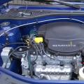
The appearance of the block is shown in Fig. 2. 15-pin connector is used to connect power and sensors.

The output signals of the sensors are coming from the contacts of the XP1 connector to the inputs P0.0-P0.5, P2.0-P2.5 microcontroller DD3 through the matching chains of A1V1-A1V12 and Schmitt Triggers DD1, DD2. Outputs P1.0-P1.7, P3.1, P3.2 microcontroller are designed to control the transistor keys A2B1-A2B10, which, in turn, commute the HL1- HL10 LEDs. To form a bell signal, imitating the ringing of the bell, serves as a dynamic head of B1, which is connected through a C9 separator condenser to the output of the amplifier on the transistors VT7, VT8, controlled by the RZ.B, P3.7, DD3 microcontroller.
When the key is inserted into the car ignition lock, the supply voltage comes from the contact 11 of the XP1 connector through the VD9 diode, which protects the block from the ransom to the voltage stabilizer, made on the VT1-VT6 transistors. The VD11R8R9VT6 circuit turns off the power supply if the voltage is on-board network exceeds 24 V. Stabilizer provides a minimal voltage drop (not more than 0.6 V at full load) and allowing the pulse input voltage to 150 V.
The DD3 microcontroller contains a built-in clock generator, working with an external ceramic resonator CSA-8.0MTZ of the company Mshatan8MHz.
Resetting a fixed duration for a DD3 microcontroller after supplying the supply voltage or if it decreases below 4.2 V generates a node ("Supervisor"), consisting of a threshold element on the VT10 transistor, VD12 stabitron and a single manufacturer on elements DD4.3, DD4.4 . In standby mode (Ignition is turned off, the front doors are closed) The DD3 microcontroller is located in the "sleep" condition, while the current consumed by the unit does not exceed 7.5 mA. If the key in the lock is turned to the "ignition" position or open any front door, the node on the DD4.1 element and the VT9 transistor generates an interrupt (log. 0) at the output of the DD3 microcontroller, withdrawing it from the "sleep" state.
The block indicates the open state of each car door. To save an individual signal from each door switch and include lighting in the cabin when opening any door, VD5-VD8 diodes are applied. VD1-VD4 diodes prevent supply voltage to the block through the lighting lamp of the car interior.
The block mainly applies elements for surface mounting. CONDENSER C9 - Jamicon SKR101M1EE111VM SKR101M1EE11VM (admissible to a similar), C3 condenser - tantalum size D for surface mounting, all other capacitors and resistors of sizes 06033, 0805 and 1206. MJE15031 and 2N5401 transistors can be replaced by KT851A and CT6116A, and transistors SUP847 and SPE857 - on CT3130A-9-CT3130ZH-9 and CT3129A-9-KT3129D-9, respectively.
Literature
- Pyatkov K. B., Ignatov A. P., Kosarev S. N., etc. Cars VAZ-2110 and VAZ-21102: Guide to maintenance and repair. - M.: Driving, 1996.
- Stashin V. V., Urusov, A. V., Mologtseva O. F. Design of digital devices on one-chip microcontrollers. - M.: Energoatomizdat, 1990.
- ATMEL CORPORATION 8051 Flash Microcontroller Data Book. 1997.
1 - button to install and adjust the current time on the clock.
If you need to change or set the time reading, you must click this button. The clock arrow will change the position for one minute. If you click on the button once.
2 - alarm that reports a malfunction overall light and braking signal lamps.
After turning on ignitionThe control system is validated by the status of lamps. If a malfunction is detected, lights up signalizer orange light. The operation of the alarms is possible only when the ignition is turned on. After turning on the ignition, all the alarms are displayed by the indication unit. This is intended to ensure that the driver can be convinced of the health of all the alarms. After the system produces self-diagnostics and will not be detected by various faults, all the alarms should go out.
3 - Signaling of an unused seat belt. The signaling device lights up with red light. It works only when the ignition is on.
4 - alarm device reporting to wear brake pads. It is not installed on all cars and only on those equipped with brake pads with wear sensors. It works only when the ignition is on.
5 - the signaling device of the unclosed doors. After opening the door, when the ignition is turned on, it lights up with a red light. It works only when the ignition is on.
6 - alarm low level Coolant B. expansion tank. It has orange light. It works only when the ignition is on.
7 - Signalizer informing a low level of fluid in a plane tank windshield. If in a tank less than one liter of the glass fluid, lights up with orange light. It works only when the ignition is on.
8 - Low Oil Signal Control in Engine Carter. When lowering the oil in the engine below the minimum lights up with orange light.
9 - Immobilizer indication.
10 - lever that allows you to control the dampers of the air distributor.
The lever in the extreme left position - the air flow is sent to the top of the cabin, which runs through the side and central ventilation grids.
The lever in the middle position - the main air flow blows the windshield.
The lever in the extreme right position is the main air flow directed to the legs of the passengers and the driver.
11 - handle for temperature adjustment. Around the handle of the temperature controller applied the scale - the temperature in degrees Celsius. This regulator sets the desired temperature in the car car. In the cabin on the ceiling, the air temperature sensor is installed, due to which the set air temperature is maintained in the cabin. When installing the adjustment knob in the blue sector, the heater will pass non-heated air. When installing the handle in the red sector, the heated air will arrive in the car.
12 – Heater control unit. Electronic system It is arranged in such a way that it automatically supports the specified temperature in the cabin, and at the same time controls the speed of rotation of the electric fan.
13 - handle for controlling the heater fan. This handle sets the speed of rotation of the electric fan and has four fixed positions.
As in any other machine, the VAZ 2110 instrument panel is designed to display the general condition of the car, to show a steady operation or problem in its main systems, as well as the speed of movement, fuel level, etc.
However, as practice shows, not for all control panel - an open book. Consider its device, instruction and description of the display light bulbs in the new and old sample panel.
Indication designations
As you know, all the light bulbs on the control panel are ignited at the moment of inclusion of ignition, and then when the engine is already running, most of them go out. But when someone remains to burn, or blinks, it cannot but disturb, because not everyone can immediately figure out what kind of faults it indicates which systems need urgent repairs.
Consider the designations of the VAZ 2110 instrument panel. You should know that regardless of whether the panel of a new or old sample is on your machine, the designations are almost the same, but there are indicators can be slightly different.
Top part
So let's start from left to right. At first - the top of the control panel:
- Side scale from 50 to 130 and arrow. Shows the temperature of the toosol (antifreeze) in the engine cooling system;
- Almost round scale (0 - 80) and arrow. Tachometer showing engine speed;
- Two arrows at the top almost in the middle of the control panel - turn signals (right, left);
- Speedometer. Well, this device is probably known, shows the speed with which the car moves;
- Side scale with the arrow and most often with two images filling column (White and red). Instead of a red column there may be a yellow light bulb. This is the fuel level indicator in the tank. If the red column lights up (yellow light), it means that there are very little fuel in the tank - no more than 7 liters, urgent refueling is required.
Bottom part
Consider the indicators at the bottom of the control panel. If they do not burn, it means that the machine works fine, and when any of them lights up - this indicates malfunctions in certain nodes. Exactly this is the signal that repair is needed, and the faster - the better. From left to right:
- The extreme left at the bottom is the indicator - the air damper light bulb (if you have a carburetor engine);
- Icon in the form of ancoal. If this light is running, it means that the engine is insufficient oil pressure. Anxious signal. Need to stop, find the cause;
- Round icon with the letter P inside, on the control panel indicates that you are turned on parking brakewhich is known to be disconnected by touched from the spot;
- A malfunction index associated with a generator or battery (on the indicator a conditional image of the battery). Perhaps the battery charge does not work from the generator, there is a break in the chain, the generator belt is weak or cut. In any case, you need your intervention and repair, otherwise troubles are not avoided;
- If the engine works, and at the same time on the control panel check. Indicator Engine is the most unpleasant for the driver, as it indicates serious malfunctions in the engine. In general, when you light up this indicator, it is recommended to stop moving off the engine. Most likely, he needs repairs;
- Usually above Check Engine Located a red triangle. It burns when the "accident" works - alarm sign;
- Light bulb with the image of the headlight indicates what is enabled far light. Designed to control light headlights: when an oncoming car appears, do not forget to switch to the near light;
- A very important indication icon, which has the front panel (in a red circle) - a signal that is not enough brake fluid. It may be possible somewhere that it is desirable to find out as soon as possible and, if necessary, carry out urgent repairs, replenish the level;
- The burning light icon is control over the inclusion of dimensions;
- In addition to the indicated light bulbs, the front control panel has time pointers (and the button to set the clock and minutes) as well as the display on which the common and daytime mileage is reflected. On the new sample panel, this display can be narrow.
Deciphering the car error codes is presented in this material:
Additional panel
Additional front panel BSC of the new sample has indicators:
- Depicted Maslenka. If the light is running - check the oil level;
- The icon lights up, in which at some fantasy you can "identify" working wipers. This suggests that little washing fluid for glasses in a tank;
- The conditional image of the thermowner over a container with a liquid is a high temperature of anthem;
- The crossed out light bulb on which the arrow indicates is a sign that the stop signal or dimensions does not work;
- If the light bulb is lighting with the image of the brake pads, it is possible that the pads were worn and require replacement;
- A man's sign with a seat belt says that the belt should be fastened.
Removal and refinement
In short, the device and control panel icons. If for some reason it refused, you should not immediately fall into panic. Most often, the reason in the absence of contacts in the wiring. But of course, if you wish, you can completely change or make tuning panels.
Make tuning backlight dashboard This material will help:
For example, removing the lining, replace the light bulbs with brighter LEDs. Such a panel works brighter and signals supplied by the car will be noticeable for the driver. If desired, you can install more solid, which transforms the salon.
To remove the panel, you need:
- Disconnect the Wire "-" AKB;
- Remove by unscrewing the screws;
- Remove the fastenings of the control panel to the lining, remove the instrument combination from the jack;
- Remove the glass mask;
- Disconnect the wires with the shoe;
- Make changes to the instrument panel or replace it with a new one. Collect everything in reverse order.
Side Control System (BSK) - Very useful thing in the car! But for some reason, the "dozens" survey of the sensors is carried out only when the ignition is turned on. That is, if you felt the liquid into the tank, then in order for the indicator to the BSC to go, you need to off / incl. Ignition. In the article I will show how modify BSK to work in real time.
Default BSK conducts a survey of all sensors Only when the ignition is turned on. This means that if the coolant level fell (due to its leakage) or the water ends for washing windshieldThe driver does not know about it until the next time will not include the ignition.
The BSC unit issues the following parameters:
1. An insufficient oil level alarm - and so normally works with its 10-minute delay, so it does not touch it.
2. Lamps malfunctioning, also triggers normally and when the engine is running.
3,4,5,6. Four signaling devices of unclosed doors, their work is also quite suitable.
For alterations remain:
7. Insufficient leveling fluid alarm.
8. An insufficient coolant signaling device in an expansion tank.
9. Warning signaling device of the front pads.
10. Signaling device not fastened driver safety belts.
The last two parameters from the factory do not work, because Sensors are not installed, I used them for other purposes:
1) Connect to the wear alert opener Bach Level Sensor
2) to the signaling of not fastened belts washer Tank Level Sensor rear glass.
Redighted the alarms for a drop in the expansion tank and in washer tanks.
The meaning of this refinement is to disconnect the LEDs of the indicators you need from the board and connect them directly (through resistance) to the BSC plug.
2. Old sample with long housing. Unlike a new sample, there is a lot of free space and a plug separately from the board connected to it with wires. I had a block of an old sample.
3. Then, the same wires, only on the other hand, dropped from the plug, soldered at their resistance areas, and the wires themselves succeeded to resistance. Resistance used 620 ohms, with a capacity of 0.125W.
After such a finalization of the BSK, the indicators work when the ignition is turned on, and light up immediately when the sensor is triggered. The sound signaling device does not work with them (with a decrease in the level of the liquid, on the irregularities of the road, he tortures his pilikan.)
Instead of the "belts" and "pads" icons made its levels of fluids.
My friend, Roma112, painted in CorelDRAW layout of a new insert with new icons " liquid level in headlight washer tank "And" liquid level in rear window washer tank ". I printed this layout on the photophonating machine and illuminated by matte film.
Perhaps you will be interested in how to make a backlight of the BSC block.
Source photo:
- BSC Display In Real Time Site
- Cardinal refinement BSK from the forum MY2110.RU
http: //XN--2111-43DA1A8C.XN--P1AI
The block may be in one of the five modes:
- turned off;
- waiting mode;
- preliminary control of the alarms (testing);
- preliminary control of parameters (sensor status);
- Control of parameters when engine operation.
When you open any door of the car, the block must include the interior lighting.
"Disabled" mode
When the key is not inserted into ignition switchThe block is in "Disabled" mode.
Waiting mode
After inserting the key in ignition switch The block goes into the "waiting mode" and remains in it until the key in the ignition switch is in position 0 ("off").
If the driver's door is opened in this mode, the "Forgotten key in the ignition switch" occurs in this mode, and the audio signal starts the intermittent beep for (8 ± 2) p. The signal must disconnect if you close the door, or remove the key from the ignition switch, or rotate the key to another position.
Testing
At the same time controlled malfunctions on level sensors and their state is remembered. Until the end of the test, the signaling status of the sensors is not performed.
Pre-depotcontrol parameters
After the testing is completed, the pause and block goes to the pre-depot control mode. In this case, the alarm of faults (if any) is made according to the following algorithm:
- LED alarms of those parameters that went beyond the limits of the norm begin to flash during (8 ± 2) with, after which they begin to burn constantly until the key turns into the ignition switch to the "0" position ("off");
- Simultaneously and synchronously with LED alarms, a sound alarm is turned on, which is turned off (8 ± 2) s.
Control parameterswhen working the engine
In this latter mode, the block goes after the end of the previous mode. At the same time, the control of the parameters of the level sensors is terminated and only the other parameters are controlled.
If a malfunction occurs during the movement, the alarm is repeated according to the algorithm given for the "Pre-deploy control of parameters".
If during sound and LED alarm key in the ignition switch translate to the "0" position ("off"), then sound and light alarm must turn off.
In the event of faults like "Brake pads" or "Blowing threads of lamps", a malfunction must occur before the end of the trip [before the key turning to the "0" position ("off")].
If for (8 ± 2) from after the start of the light and sound alarm, another or more "fault" signals will appear, the flashing light indication should turn around to a flat light, and the light indication of the newly received signals should be included according to the described algorithm.