Current generator converts mechanical (kinetic) energy into electrical energy. In power engineering, only rotating electric machine generators are used, based on the occurrence of an electromotive force (EMF) in a conductor, which is in some way acted upon by a changing magnetic field. The part of the generator, which is designed to create a magnetic field, is called an inductor, and the part in which an EMF is induced is called an armature.
The rotating part of the machine is called rotor, and the fixed part - stator... In synchronous machines alternating current the inductor is usually the rotor, and in machines direct current - stator. In both cases, the inductor is usually a two- or multi-pole electromagnetic system equipped with an excitation winding supplied with direct current (excitation current), but there are also inductors consisting of a system of permanent magnets. In induction (asynchronous) alternators the inductor and the armature cannot clearly (structurally) differ from each other (we can say that the stator and the rotor are both an inductor and an armature at the same time).
More than 95% of the electricity in the world's power plants is produced using synchronous alternators... With the help of a rotating inductor, a rotating magnetic field is created in these generators, which induces a variable EMF in the stator (usually three-phase) winding, the frequency of which exactly matches the rotor speed (it is in synchronism with the inductor speed). If the inductor, for example, has two poles and rotates at a frequency of 3000 r / min (50 r / s), then an alternating EMF with a frequency of 50 Hz is induced in each phase of the stator winding. The design of such a generator is simplified in Fig. 1.
Figure: 1. The principle of a two-pole synchronous generator. 1 stator (armature), 2 rotor (inductor), 3 shaft, 4 housing. U-X, V-Y, W-Z - parts of the windings of three phases located in the stator slots
The stator magnetic system is a compressed package of thin steel sheets, in the grooves of which the stator winding is located. The winding consists of three phases, shifted in the case of a two-pole machine relative to each other by 1/3 of the stator perimeter; in the phase windings, therefore, EMFs are induced, shifted relative to each other by 120o. The winding of each phase, in turn, consists of multi-turn coils connected in series or in parallel. One of the simplest design options for such a three-phase winding of a two-pole generator is simplified in Fig. 2 (usually the number of coils in each phase is more than shown in this figure). Those parts of the coils that are outside the grooves on the stator front surface are called end connections.
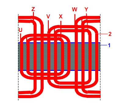
Figure: 2. The simplest principle of the stator winding arrangement of a three-phase two-pole synchronous generator in the case of two coils in each phase. 1 scan of the surface of the stator magnetic system, 2 winding coils, U, V, W the beginning of the phase windings, X, Y, Z ends of the phase windings
There may be more than two poles of the inductor and, accordingly, the pole divisions of the stator. The slower the rotor rotates, the larger the number of poles should be at a given current frequency. If, for example, the rotor rotates at a frequency of 300 r / min, then the number of generator poles, to obtain an alternating current frequency of 50 Hz, should be 20. For example, at one of the largest hydroelectric power plants in the world, the Itaipu HPP (Itaipu, see Fig. 4) generators operating at 50 Hz are 66-pole, and generators operating at 60 Hz are 78-pole.
The excitation winding of a two- or four-pole generator is placed as shown in fig. 1, in the grooves of the massive steel rotor core. This design of the rotor is necessary in the case of high-speed generators operating at a speed of 3000 or 1500 r / min (especially for turbine generators intended for connection with steam turbines), since at this speed, large centrifugal forces act on the rotor winding. With a larger number of poles, each pole has a separate field winding (Fig. 3.12.3). This salient-pole principle of the device is used, in particular, in the case of low-speed generators designed to be connected to hydraulic turbines (hydrogenerators), usually operating at a speed of 60 r / min to 600 r / min.
Very often such generators, in accordance with constructive performance powerful hydraulic turbines are made with a vertical shaft.

Figure: 3. The principle of the rotor design of a low-speed synchronous generator. 1 pole, 2 excitation winding, 3 mounting wheel, 4 shaft
Excitation winding synchronous generator usually supplied with direct current from an external source through slip rings on the rotor shaft. Previously, a special DC generator (exciter) was provided for this, rigidly connected to the generator shaft, and now simpler and cheaper semiconductor rectifiers are used. There are also excitation systems built into the rotor, in which the EMF is induced stator winding... If permanent magnets are used to create a magnetic field instead of an electromagnetic system, then the excitation current source disappears and the generator becomes much simpler and more reliable, but at the same time and more expensive. Therefore, permanent magnets are usually used in relatively low-power generators (up to several hundred kilowatts).
The design of the turbine generators, thanks to the relatively small diameter cylindrical rotor, is very compact. Their specific gravity is usually 0.5 ... 1 kg / kW and their rated power can reach 1600 MW. The device of hydrogenerators is somewhat more complicated, the rotor diameter is large and their specific weight is therefore usually 3.5 ... 6 kg / kW. Until now, they have been manufactured with a rated power of up to 800 MW.
When the generator is operating, energy losses occur in it, caused by the active resistance of the windings (losses in copper), eddy currents and hysteresis in the active parts of the magnetic system (losses in steel) and friction in the bearings of rotating parts (friction losses). Despite the fact that the total losses usually do not exceed 1 ... 2% of the generator's capacity, the removal of heat released as a result of losses can be difficult. If we assume in a simplified way that the mass of the generator is proportional to its power, then its linear dimensions are proportional to the cubic root of the power, and the surface dimensions are proportional to the power to the power of 2/3. With increasing power, therefore, the heat sink surface grows more slowly than the rated power of the generator. If, at powers of the order of several hundred kilowatts, it is enough to use natural cooling, then at higher capacities it is necessary to switch to forced ventilation and starting at about 100 MW use hydrogen instead of air. At even higher capacities (for example, over 500 MW), it is necessary to supplement the hydrogen cooling with water. In large generators, the bearings must also be specially cooled, usually using oil circulation.
The heat generation of the generator can be significantly reduced by using superconducting field windings. The first such generator (4 MVA), intended for use on ships, was manufactured in 2005 by the German electrical engineering firm Siemens (Siemens AG). The nominal voltage of synchronous generators, depending on the power, is usually in the range from 400 V to 24 kV. Higher rated voltages (up to 150 kV) were also used, but extremely rarely. In addition to synchronous generators of mains frequency (50 Hz or 60 Hz), also high frequency generators (up to 30 kHz) and reduced frequency generators (16.67 Hz or 25 Hz) used on the electrified railways of some European countries. Synchronous generators, in principle, also include a synchronous compensator, which is a synchronous motor operating on idling and delivering reactive power to the high-voltage distribution network. With the help of such a machine, it is possible to cover the reactive power consumption of local industrial electrical consumers and to free the main grid of the power system from reactive power transmission.
In addition to synchronous generators, it is relatively rare and at relatively low powers (up to several megawatts) that asynchronous generators... In the rotor winding of such a generator, the current is induced by the stator magnetic field if the rotor rotates faster than the stator rotating magnetic field of the mains frequency. The need for such generators usually arises when it is impossible to provide a constant rotation speed of the prime mover (for example, a wind turbine, some small hydro turbines, etc.).
Have dC generator the magnetic poles together with the field winding are usually located in the stator, and the armature winding is located in the rotor. Since a variable EMF is induced in the rotor winding during its rotation, the armature must be equipped with a collector (switch), with the help of which a constant EMF is obtained at the output of the generator (on the collector brushes). Currently, DC generators are rarely used, since direct current is easier to obtain using semiconductor rectifiers.
Electric machine generators include electrostatic generators, on the rotating part of which a high voltage electric charge is created by friction (triboelectrically). The first such generator (a manually rotated sulfur ball, which was electrified by friction against a human hand) was made in 1663 by the mayor of the city of Magdeburg (Magdeburg, Germany) Otto von Guericke (1602-1686). In the course of their development, such generators made it possible to discover many electrical phenomena and patterns. Even now they have not lost their importance as a means of conducting experimental research in physics.
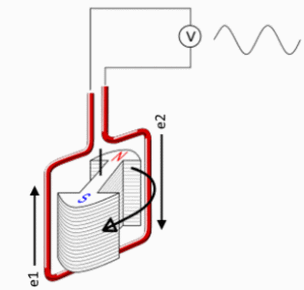
The first was made on November 4, 1831 by the professor of the Royal Institution (Royal Institution) Michael Faraday (Michael Faraday, 1791-1867). The generator consisted of a horseshoe-shaped permanent magnet and a copper disk rotating between the magnetic poles (Figure 3.12.4). When the disk rotated between its axis and the edge, a constant EMF was induced. More advanced unipolar generators are arranged according to the same principle, which are still in use (although relatively rarely).

Figure: 4. The principle of the device unipolar generator Michael Faraday. 1 magnet, 2 rotating copper disc, 3 brushes. Disc handle not shown
Michael Faraday was born into a poor family and after primary school, at the age of 13, became an apprentice of a bookbinder. From books, he continued his education on his own, and from the British Encyclopedia he got acquainted with electricity, made an electrostatic generator and a Leyden jar. To expand his knowledge, he began attending public lectures on chemistry by the director of the Royal Institute, Humphrey Davy (1778–1829), and in 1813 was promoted to his assistant. In 1821 he became chief inspector of this institute, in 1824 - a member of the Royal Society (Royal Society) and in 1827 - professor of chemistry at the Royal Institute. In 1821, he began his famous experiments on electricity, during which he proposed the principle of operation of an electric motor, discovered the phenomenon of electromagnetic induction, the principle of a magnetoelectric generator, the laws of electrolysis and many other fundamental physical phenomena. A year after the above-described Faraday experiment, on September 3, 1832, the Parisian mechanic Hippolyte Pixii (1808-1835) made, by order and under the guidance of the founder of electrodynamics, Andre Marie Ampere (1775-1836), a generator with a manually rotated at Faraday, a magnet (Fig. 5). A variable EMF is induced in the armature winding of the Pixie generator. To rectify the resulting current, an open mercury switch was first attached to the generator, switching the polarity of the EMF at each half-revolution of the rotor, but it was soon replaced by a simpler and safer cylindrical brush collector, shown in Fig. five.

Figure: 5. The principle of the device magnetoelectric generator Ippolita Pixie (a), the graph of the induced EMF (b) and the graph of the pulsating constant EMF obtained with the help of the collector (c). Handle and tapered gear not shown
The generator, built on the Pixie principle, was first used in 1842 at his plant in Birmingham (Birmingham) for power supply of galvanic baths by the English industrialist John Stephen Woolrich (1790-1843), using as a drive motor steam machine with a capacity of 1 liter. from. Its generator voltage was 3 V, the rated current was 25 A, and the efficiency was about 10%. The same, but more powerful generators quickly began to be introduced in other electroplating enterprises in Europe. In 1851, the German military doctor Wilhelm Josef Sinsteden (1803-1891) proposed using electromagnets instead of permanent magnets in the inductor and supplying them with current from a smaller auxiliary generator; he also discovered that the efficiency of the generator would increase if the steel core of the electromagnet was made not massive, but from parallel wires. However, the ideas of Sinsteden began to be actually used only in 1863 by the English self-taught electrical engineer Henry Wilde (1833-1919), who proposed, among other innovations, to plant an exciter machine (English exitatrice) on the generator shaft. In 1865, he manufactured a generator of an unprecedented power of 1 kW, with which he could even demonstrate the melting and welding of metals.
The most important improvement dC generators became their self-excitation, the principle of which was patented in 1854 chief Engineer state railways of Denmark Soren Hjorth (1801-1870), but did not find at that time practical application... In 1866, this principle was again discovered independently by several electrical engineers, including the already mentioned G. Wilde, but it became widely known in December 1866, when the German industrialist Ernst Werner von Siemens (1816-1892) applied it in my compact and highly efficient generator. On January 17, 1867, his famous lecture on the dynamo-electric principle (self-excitation) was read at the Berlin Academy of Sciences. Self-excitation allowed to refuse from auxiliary excitation generators (from exciters), which made it possible to generate much cheaper electricity in large quantities. For this reason, the year 1866 is often considered the birth year of high current electrical engineering. In the first self-excited generators, the excitation winding was included, as in Siemens, in series (serial) with an armature winding, but in February 1867, the English electrical engineer Charles Wheatstone (1802-1875) proposed parallel excitation, which allows better control of the EMF of the generator to which he came even before the reports of sequential excitation discovered by Siemens (Fig. 6).

Figure: 6. Development of excitation systems for DC generators. a permanent magnet excitation (1831), b external excitation (1851), c sequential self-excitation (1866), d parallel self-excitation (1867). 1 armature, 2 excitation winding. Regulating rheostats of the excitation current are not shown.
The need for alternators originated in 1876, when the Russian electrical engineer Pavel Yablochkov (1847–1894), working in Paris, began to illuminate the city streets with the help of alternating current arc lamps (Yablochkov candles) that he manufactured. The first generators necessary for this were created by the Parisian inventor and industrialist Zenobe Theophile Gramme (1826-1901). With the beginning mass production Incandescent lamps in 1879, alternating current lost its value for a while, but gained relevance again due to the increase in the transmission range of electricity in the mid-1880s. In 1888-1890, the owner of his own research laboratory Tesla-Electric (Tesla-Electric Co., New York, USA), the Serbian electrical engineer who emigrated to the United States, Nikola Tesla (Nikola Tesla, 1856-1943) and the chief engineer of the AEG company (AEG, Allgemeine Elektricitats-Gesellschaft) Russian electrical engineer Mikhail Dolivo-Dobrovolsky (1862-1919) who emigrated to Germany developed a three-phase AC system. As a result, the production of more and more powerful synchronous generators for heat and hydroelectric power plants under construction.
An important stage in the development of turbine generators can be considered the development in 1898 of a cylindrical rotor by the co-owner of the Swiss electrical plant Brown, Boveri and the company (Brown, Boveri & Cie., BBC) Charles Eugen Lancelot Brown (1863-1924). The first hydrogen-cooled generator (with a capacity of 25 MW) was produced in 1937 by the American company General Electric, and with in-line water cooling - in 1956 by the English company Metropolitan Vickers.
The universe has provided humanity with a trillion ways to get electricity, each stage of development is characterized by its own technologies. For example, historically, the van de Graaff constant charge generator is considered the first. Wrong point of view. People have used other varieties before. Today we will consider the device, the principle of operation of the alternator. Let's get started.
Electric current generators
The principle is designed to create a potential relative to the Earth, considered zero. Wrong, but everything in the world is relative. Although the earth's surface carries charge, the potential difference between the generator terminals and the soil plays a role. An object standing on the ground is enveloped by the field of the planet, we consider the postulate correct. The first DC generator was invented. Rather tension. The voltage turned out to be fantastic, the device gave little current. The principle of operation is simple:
The principle of the generator
- The tape rubs, a charge is formed locally.
- The section reaches the collector via the conveyor mechanism.
- The density is equalized by the conductivity of the ball-type terminal.
As a result, the sphere acquires a charge equal to that of the local ribbon. It is clear that such generators are not very convenient, in 1831 Michael Faraday creates something new. Using a magnetized horse shoe, a rotating copper disk received electricity in a different way: the phenomenon of magnetic induction. The current came out alternating. Consequently, the field has ceased to be static, becoming electromagnetic. Let's explain:
- In nature, charges of electricity of a positive or negative sign are often found; no one could find separately the poles of a magnet.
- The alternating electric field causes the corresponding response of the ether. Expressed by the production of a variable magnetic component in the plane perpendicular to the original.
The process goes on continuously, it is called an electromagnetic wave. Mastering free space in a straight line, while the energy dies out. When it comes to wires, electricity is relatively easy to spread. But! While the cable is braided. The screen is gone, there is no grounding (grounding) - the wave begins to be emitted. The effect is exploited by wireless indicator screwdrivers, helping to establish (localize) sources of interference at industrial frequency 50 Hz. And if the system unit of the computer is not grounded, with the help of a little thing, you can easily correct the defect.
Helps check for harmful radiation from displays. The 50 Hz frequency is easily radiated by wires. Aspect increases the costs of power plants (losses), harms the health of citizens. How does energy arise in a Faraday generator? School teachers explained: when the frame rotates in the field of a magnet, the induction through the area changes, an electric current is induced.
The mechanical energy of movement is converted into electrical energy. Guessed it, humanity exploits:
- Falling down of masses of water from the dam.
- Steam energy from thermal, nuclear power plants.
Two major mechanisms getting energy. Electricity becomes the movement of the turbine blades of a generator. Nature gave birth to devices that burn diesel fuel, kerosene, the principle of operation is not much different. The difference is limited by mobility, blade speed.
Electricity generation in cities
Let's see the device of the hydroelectric power plant current generator. A dam is erected to accumulate potential energy driven by the river bed. The upstream level quickly begins to rise. To avoid a breakthrough (of any type), a part of the multi-ton mass is released (in some places special locks are placed to let the fish go to spawn). The useful part of the flow passes through the guide vanes. Familiar with the device jet engines, understood the speech. The guide vane is called the configuration of the flaps; by changing the position, the amount of the passing medium (water) is regulated.
They said in the reviews that strict requirements for the frequency of electricity generated are regulated. Scientists have calculated: it is possible to achieve at the current level of development, using massive blades, which are not affected by minor impacts of waves. The average mass of passing water is taken into account, small jumps are hidden by the incredible mass of the propeller. Obviously, having weighty dimensions, the rotation speed is powerless to be 50 Hz (3000 rpm). The blade makes 1-2 rpm.

The screw turns the rotor of the generator. Moving axis seated with field windings. Coils through which a direct current is passed to create a stable magnetic field. No radiation occurs, the value of the intensity is constant (see above). Insignificant fluctuations were observed, the result does not affect the essence of the process: the shaft is formed by several rotating magnets.
One emerges subtle moment: how to get 50 Hz frequency. They quickly came to the conclusion: it is unprofitable to rectify the alternating current, then install the inverter of the reverse conversion. A plurality of wire coils (frame from Faraday's experiments) were placed along the stator, in which induction will be induced. By correct commutation, it is possible to remove the required 230 volts from the generator (in fact, there are still step-down transformers) with a frequency of 50 Hz. The generators produce three phases shifted 120 degrees. A new question arises - to ensure stability. Dispense a metered amount of water while the blade picks up speed? Practically impossible, proceed as follows:
- In addition to the collector coils, the stator contains exciting ones.
- There is a voltage of frequency that allows the blades to pick up the desired speed.
- It turns out in fact a huge synchronous motor.
The initial acceleration is overtaken by the water flow, the auxiliary voltage holds the screw trying to exceed set speed... The water actually pushes the colossus, the excitation voltage will serve as regulation (of course, alternating current is supplied to the stator). You want to get more power, the dam guide vanes slightly open. The mass of water is becoming more solid, it would definitely break the speed. It is necessary to increase the stator excitation current, the control field becomes stronger, the situation remains within normal limits.

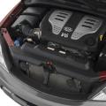
Engine internal combustion Caterpillar rotating generator
The generator power increases. Is the voltage maintained at the level? According to Faraday's law of electromagnetic emf, the voltage is determined by the rate of change of the magnetic field, the number of turns. It turns out that by constructively choosing the area of \u200b\u200bthe coils, the length of the cable, we set the output voltage of the generator. Of course, everyone should have their own blade rotation speed. Withstands rotor excitation current. With increasing power, the EMF increases. An increase in the excitation current increases the rate of change in the magnetic field strength.
We need a way to maintain the same parameters. Isolation transformers with variable gain are often used. The consumer changes the current, the voltage remains constant. The parameters specified by the standards are provided. The device of the alternator is based on the excitation of the stator windings, the rest comes down to the methods of regulating the parameters.
Adjustment by parameter of alternators
In the simplest case, the power cannot be changed. In household (small generators), the circuit monitors the voltage, the value of the excitation current changes. Rarely is the situation in the hands of the consumer. Diesel fuel is consumed. It turns out that the old energy is wasted, some of it is scattered by space. It's not scary when we return to the Earth a part of the river's speed, a rare miser wants to burn fuel for free.
Readers understood: the speed can break down if the supply of water, gas, steam - in general, the driving force is not reduced. Monitors a separate control circuit equipped with adjusting mechanisms. It is more efficient for a private house to create a rechargeable system; today it is possible to supply lighting, laptops, and many other devices with 12 volts of direct current. The network can be equipped with a branch for periodic battery charging. As we remember, there are two methods:

- With constant current. The voltage varies, one tenth of the capacity is charged every hour. The process lasts 600 minutes.
- FROM constant voltage... The current drops exponentially, at first it will be relatively large values. The main disadvantage techniques.
The principle of operation of the alternator will allow you to recharge the batteries, guided by the need. It is understood that a galvanic isolation circuit will be required before the battery cascade. You can guess from what you read, hydroelectric power plants use devices with an adjustable transformation ratio. Methods for implementing an idea may be different:
- Transformers with switched windings are widely used. The number of turns can be changed by switching circuit contactors.
- A smoother ratio provides sliding contact. Here the turns of one coil are cleaned, the current collector runs back and forth, changing the number of working turns. It is clear that it is difficult to pass a large current, a spark will arise, in the case of a hydroelectric power station it will become an arc. Rather, a device for regulating relatively small powers.
From the above it follows: it is logical to change the excitation current of the hydroelectric power plant rotor in jumps in time with the switching of the windings of the regulating transformer. Then a smooth adjustment follows, the voltage parameters return to normal. Told in in general termshow an alternator works. It should be noted that the variety is not exhausted by the construction. This view devices form the backbone of a family called synchronous alternators. Providing cities, for the most part, with energy.
Asynchronous alternator
Asynchronous generators are characterized by the absence of electrical connection between the stator and the rotor. The speed is regulated by the guide vanes. Accordingly, the frequency stability drops, the voltage amplitude is also unstable. As a result, we can note the relative simplicity of the design of the asynchronous alternator, the stability of the parameters does not shine with good performance.
A distinctive feature is the ability of disadvantages asynchronous motors smoothly migrate, infecting new devices. Obviously, to supply consumers with energy, the frequency of the current is regulated, the power is obtained random. However, if the generator is in a relatively permanent environment, this will not be a big problem.
An alternator or direct current generator is a device for generating electricity by converting mechanical energy.
What an alternator looks like
How does an alternator work? A current is generated in a conductor by a magnetic field. It is convenient to generate current by rotating a rectangular electrically conductive frame in a stationary field or a permanent magnet inside it.
When it rotates around the axis of the magnetic field it creates inside the frame with angular velocity ω, the vertical sides of the contour will be active since they are crossed by the magnetic lines. There is no action on the horizontal sides coinciding in the direction with the magnetic field. Therefore, no current is induced in them.
What does a generator with a magnetic rotor look like?
EMF in the frame will be:
e = 2 B max lv sin ωt,
B max - maximum induction, T;
l - frame height, m;
v - frame speed, m / s;
t - time, s.
Thus, from the action of the changing magnetic field in the conductor, an alternating EMF is induced.
For a large number of turns wby expressing the formula in terms of the maximum flow F m, we get the following expression:
e = wF m sin ω t.
The principle of operation of another type of alternator is based on the rotation of a conductive frame between two permanent magnets with opposite poles. The simplest example is shown in the figure below. The voltage appearing in it is removed by slip rings.

Permanent magnet current generator
The use of the device is not very common due to the load of the moving contacts with a large current passing through the rotor. The design of the first given version also contains them, but much less direct current is supplied through them through the turns of the rotating electromagnet, and the main power is removed from the stationary stator winding.
Synchronous generator
A feature of the device is the equality between the frequency f, induced in the stator EMF and rotor speed ω :
ω \u003d 60 ∙f/ p rpm,
where p - the number of pole pairs in the stator winding.
The synchronous generator creates an EMF in the stator winding, the instantaneous value of which is determined from the expression:
e \u003d 2π B max lwDn sinω t,
where land D - length and inner diameter of the stator core.
The synchronous generator produces a voltage with a sinusoidal characteristic. When connected to its terminals C 1, C 2, C 3 consumers, a single or three-phase current flows through the circuit, the circuit is below.
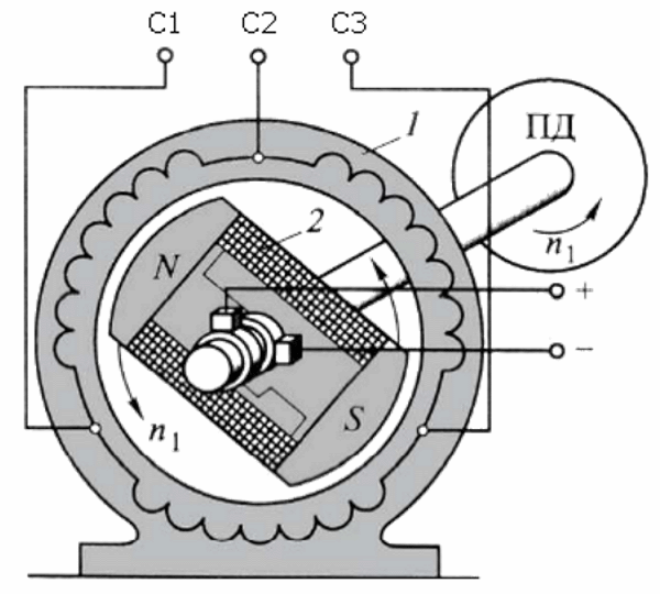
Three-phase synchronous generator circuit
The action of the changing electrical load also changes the mechanical load. This increases or decreases the speed of rotation, resulting in a change in voltage and frequency. To prevent such a change from happening, electrical characteristics automatically maintain at a given level through the voltage and current feedbacks on the rotor winding. If the rotor of the generator is made of a permanent magnet, it has a limited ability to stabilize electrical parameters.
The rotor is forced to rotate. An induction current is supplied to its winding. In the stator, the rotor magnetic field, rotating at the same speed, induces 3 alternating EMFs with a phase shift.
The main magnetic flux of the generator is created by the action of a direct current passing through the rotor winding. Power may come from another source. The self-excitation method is also common, when a small part of the alternating current is taken from the stator winding and passes through the rotor winding after pre-straightening. The process is based on residual magnetism, which is sufficient to start the generator.
The main devices that generate almost all of the world's electricity are synchronous hydro or turbine generators.
Asynchronous generator
The device of an asynchronous type alternator differs in the difference in the EMF rotation frequency ω and rotor ω r. It is expressed through a coefficient called slip:
s \u003d (ω - ω r) / ω.
In operating mode, the magnetic field slows down the rotation of the armature and its frequency is lower.
An induction motor can operate in a generator mode if ω r\u003e ω, when the current changes direction and energy is given back to the network. Here the electromagnetic moment becomes braking. The use of this property is common when lowering loads or on electric vehicles.
An asynchronous generator is chosen when the requirements for electrical parameters are not very high. In the presence of inrush overloads, a synchronous generator is preferable.
Device car generator is no different from the usual, generating electric current. It generates alternating current, which is then rectified.
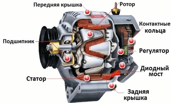
What a car generator looks like
The design consists of an electromagnetic rotor rotating in two bearings driven by a pulley. It has only one winding, with direct current supply through 2 copper rings and graphite brushes.
The electronic relay regulator maintains a stable voltage of 12V, independent of the rotation speed.
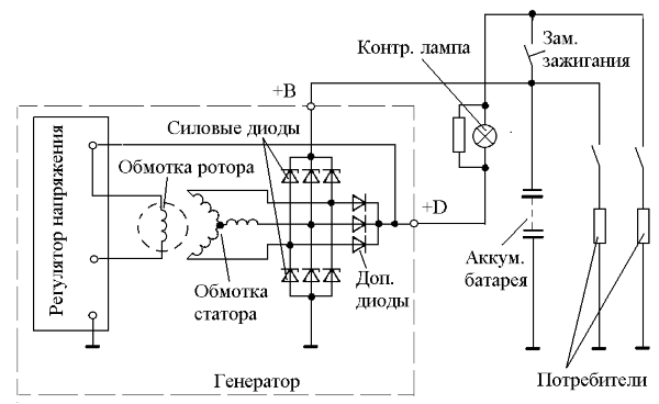
Automotive generator circuit
The current from the battery goes to the rotor winding through the voltage regulator. The moment of rotation is transmitted to it through the pulley and EMF is induced in the turns of the stator winding. The generated three-phase current is rectified by diodes. Maintaining a constant output voltage is performed by a regulator that controls the field current.
As the motor rises, the field current decreases, which helps maintain a constant output voltage.
Classic generator
The design contains a liquid fuel engine that drives a generator. The rotor speed must be stable, otherwise the quality of electricity generation decreases. When the generator is worn out, the rotation speed becomes lower, which is a significant disadvantage of the device.
If the load on the generator is below the rated load, it will partially idle, consuming excess fuel.
Therefore, it is important when purchasing it to make an accurate calculation of the required power so that it is correctly loaded. A load below 25% is prohibited, as this affects its durability. All possible operating modes that must be observed are indicated in the passports.
Many kinds of classic models have acceptable prices, high reliability and a large power range. It is important to load it properly and have it inspected on time. The figure below shows the models of gasoline and diesel generators.
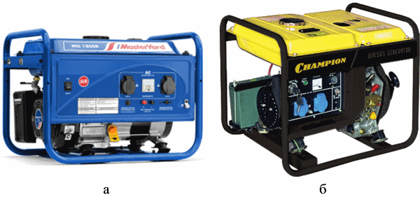
Classic generator: a) - gasoline generator, b) - diesel generator
Diesel generator
The generator drives the engine, which runs on diesel fuel... The internal combustion engine consists of a mechanical part, a control panel, a fuel supply system, cooling and lubrication. The power of the generator depends on the power of the internal combustion engine. If it is required small, for example, for household appliances, it is advisable to use a gasoline generator. Diesel generators are used wherever more power is needed.
ICEs are used in most cases with overhead valves. They are more compact, more reliable, easy to repair, and emit less toxic waste.
They prefer to choose a generator with a metal case, since plastic is less durable. Devices without brushes are more durable, and the generated voltage is more stable.
Capacity fuel tank provides operation at one gas station no more than 7 hours. In stationary installations, an external tank with a large volume is used.
Gas generator
As a source of mechanical energy, the most common four-stroke carburetor engine... For the most part, models from 1 to 6 kW are used. There are devices up to 10 kW, capable of providing a country house at a certain level. Prices gasoline generators are acceptable, and the resource is quite sufficient, although less than that of diesel engines.
The generator is selected depending on the loads.
For high starting currents and frequent use of electric welding, it is better to use a synchronous generator. If you take an induction generator more powerful, it will cope with inrush currents. However, it is important here that it is loaded, otherwise gasoline will be consumed irrationally.
Inverter generator
Machines are used where electricity is required high Quality... They can work continuously or at intervals. The objects of energy consumption here are institutions where power surges are not allowed.
The basis of the inverter generator is the electronic unitwhich consists of a rectifier, a microprocessor and a converter.

Block diagram of an inverter generator
Power generation starts in the same way as in the classic model. First, an alternating current is generated, which is then rectified and fed to the inverter, where it again turns into alternating current, with the desired parameters.
The types of inverter generators differ in the nature of the output voltage:
- rectangular - the cheapest, capable of powering only power tools;
- trapezoidal impulse - suitable for many devices, with the exception of sensitive equipment (middle price category);
- sinusoidal voltage - stable characteristics suitable for all electrical appliances (highest price).
The advantages of inverter generators:
- small size and weight;
- low fuel consumption by regulating the generation of the amount of electricity that consumers need at the moment;
- the possibility of short-term work with overload.
The disadvantages are high prices, sensitivity to temperature changes of the electronic part, low power. In addition, it is expensive to repair the electronic unit.
The inverter model is selected in the following cases:
- the device is purchased only in cases where a conventional generator is not suitable, since its price is high;
- power is required no more than 6 kW;
- classic alternators are better suited for permanent use;
- it is necessary to partially supply household appliances with electricity;
- for domestic use, it is better to use single-phase devices.
Video. Alternator.
Alternators are capable of replenishing electricity in the house in the event of a stationary device failure, and are also used anywhere where electricity is needed.
As you know, when current passes through a conductor (coil), a magnetic field is formed. Conversely, when the conductor moves up and down through the magnetic field lines, an electromotive force arises. If the movement of the conductor is slow, then the resulting electric current will be weak. The current value is directly proportional to the magnetic field strength, the number of conductors, and, accordingly, the speed of their movement.
The simplest current generator consists of a coil made in the form of a drum, on which a wire is wound. The coil is mounted on a shaft. A wire-wound drum is also called an anchor.

To remove current from the coil, the end of each wire is soldered to the current-collecting brushes. These brushes must be completely insulated from each other.
Alternator
When the armature rotates around its axis, the electromotive force changes. When the coil turns ninety degrees, the current is maximum. On the next turn, it drops to zero.

A complete revolution of the coil in the generator creates a current period or, in other words, an alternating current.

A switch is used to obtain constant current. It is a split ring into two parts, each of which is attached to different turns of the armature. When correct installation halves of the ring and current-collecting brushes, for each period of change in the current strength in the device, a direct current will flow into the external environment.

A large industrial power generator has a fixed armature called a stator. A rotor rotates inside the stator, creating a magnetic field.
Be sure to read the articles about car generators:
Any car has a power generator that works when the car is moving to supply electrical energy to the battery, ignition systems, headlights, radio, etc. The rotor field winding is the source of the magnetic field. In order for the magnetic flux of the excitation winding to be supplied without losses to the stator winding, the coils are placed in special grooves in the steel structure.
Current generator- this is electric car, which converts mechanical energy into electrical energy. They can generate both direct and alternating current.
Until the second half of the 20th century DC generators were used in vehicles. Then, semiconductor diodes became widespread, which made it possible to rectify alternating current or make it constant. Therefore, in this area, DC generators have been replaced by more reliable and compact three phase generators alternating current.
In I have examined in detail the issues of the operation of the electric motor, now they will be presented general principles work and device of the current generator. I will not dwell on DC machines in detail, because today they are not used in everyday life, in garages and on vehicles. They are only widely used in urban electric transport: trolleybuses and trams.
The principle of operation of the current generator
The generator works by the law Faraday's electromagnetic induction - electromotive force (EMF) is induced in a rectangular circuit (wire frame) rotating in a uniform rotating magnetic field.
EMF also occurs in a fixed rectangular frame if you rotate a magnet in it.
The simplest generator is a rectangular frame placed between 2 magnets with different poles. In order to remove the voltage from the rotating frame, slip rings are used. On practice electromagnets are also used, which are inductors or windings of copper wire in an insulating varnish. When passing electric current along the windings, they begin to have electromagnetic properties. To excite them, an additional current source is required - in cars this accumulator battery... In household power plants, excitation during start-up occurs as a result of self-excitation or from an additional low-power DC generator, which is driven by the generator shaft.
By the principle of work generators can be synchronous or asynchronous.
- Asynchronous generators structurally simple and inexpensive to manufacture, more resistant to short-circuit currents and overloads. An asynchronous generator is ideal for powering active loads: incandescent lamps, electric heaters, electronics, electric burners etc. But even a short-term overload is unacceptable for them, therefore, when connecting electric motors, do not electronic type welding machine, power tool and other inductive loads - the power reserve should be at least threefold, and preferably fourfold.
- Synchronous generator perfect for inductive consumers with high starting currents. They are capable of withstanding a fivefold current overload for one second.
Alternator device
For an example of considering a device, take a three-phase automobile generator. 
Car generator consists of a body and two covers with ventilation holes. The rotor rotates in 2 bearings and is driven by a pulley. At its core, a rotor is an electromagnet consisting of one winding. The current is supplied to it using two copper rings and graphite brushes, which are connected to an electronic relay-regulator. It is responsible for ensuring that the voltage output by the generator is always within the permissible range of 12 Volts with permissible deviations and does not depend on the speed of the pulley. The relay-regulator can be either built into the generator housing or outside it.
The stator consists of three copper windings connected to each other in a triangle. A rectifier bridge of 6 semiconductor diodes is connected to the points of their connection, which convert the voltage from AC to DC.
Gasoline Generator consists of a motor and driving them on a straight line - a current generator, which can be both synchronous and asynchronous type.