Electronic ignition (BSZ) on IZH Jupiter
If you install BSZ on IZH Jupiter, then even with domestic technology, you can forget about the ignition problem in general. And the engine, in turn, will work much smoother, softer, and the dynamics will improve! At speed the engine will become much more sensitive to gas, and idling - smoother and more stable. And it is easy to start even with a decently drained battery.
Installation of contactless ignition on IZH JUPITER
Installation and setup takes a maximum of one day, all parts (Hall sensor, wire harness, switch and dual-output ignition coil) fit well from Oka. In general, "Oka" is a universal car that needed to be born a motorcycle!
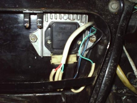
Nothing is altered on the generator: the cams are simply removed and in suitable place Hall sensor is attached. The plate - the modulator is fixed on the rotor - so that it passes clearly in the middle of the slot of the Hall sensor, the placement issues are solved with the help of washers. How everything is placed can be seen in the figures.
Scheme contactless ignition(BSZ) IZH JUPITER
Wiring diagram is also shown in the figure at the bottom of the page.
Plate - modulator:
This is where the whole secret of the stable operation of the Jupiter engine with one Hall sensor lies.
Gaps in sparking in some cases are associated with an incorrect design of the curtain-modulator (magnetic flux contactor). Pay more attention to its position in relation to the sensor. In the open state, the shutter should not overlap either the magnet or the magnetic circuit (metal "beak" at the end of the sensor); in the closed state, the modulator should completely overlap both of them. Otherwise, the sensor will give out fuzzy signals that the switch will not be able to recognize, and this is fraught with gaps in sparking, therefore, malfunctions in the motor.
The modulator should be made in the form of a disk with a cutout made of steel 0.8-1.0 mm thick, as shown in the figure. The main thing is that the ratio of the periods of the closed state of the sensor to the open state is 2: 1 (this required condition for the clear operation of the switch control chip). If the engine is 1-cylinder, then the notch angle in the modulator should be made approximately 120 degrees, if the engine is 2-cylinder, then the notch angles should be 60 degrees. It is also important to note that the minimum cutout width is 11mm. When setting the ignition timing, remember: the spark strikes when the modulator "opens" the sensor.
Before installation BSZ on IZH Jupiter make sure there is no excessive play in the generator shaft. This "carrier" of the curtain must keep within the axial runout up to 0.35 mm, and its swing in the transverse plane is limited to 0.5 mm. The modulator petals walking in excess of these norms will not fit into the narrow slot of the sensor and will smash the fragile plastic housing of the Hall sensor to smithereens. The bumpiness is most often caused by wear of the generator bearings - change them without hesitation, especially since contact ignition also "is not friends" with backlashes and will not be able to work clearly.
Setting up contactless ignition (BSZ) IZH JUPITER
When will you start tuning ignition on Izh Jupiter it may be difficult to adjust the ignition timing. But there is nothing complicated here! You can't go into electronics with a “dial” light, traditional for setting contacts. The voltmeter solves the problem - I'll tell you how to use it.
I advise you to use a device with a scale of at least 15V and an internal resistance of 10-50 kOhm. Connect it to the terminals of the Hall sensor: place the positive wire on the contact No. 2, and the negative wire on the No. 3.
Set the piston of any cylinder to the position corresponding to the moment of sparking. Turn on the ignition and turn the modulator (in the direction of rotation of the crankshaft) until the voltmeter readings change. The discharge moment on the spark plug corresponds to a voltage jump in the sensor from tenths of a Volt to a value close to the onboard power supply of a motorcycle. Having "caught" the spark without knocking down the position of the shutters, fix the modulator on the generator shaft with a mounting bolt.
It must be remembered that when adjusting the ignition, be sure to short-circuit the high-voltage wires to the engine housing or "load" them with candles. The operation of the coil with a broken secondary circuit leads to overload and damage to the BSZ. For the same reason, it is impossible to "muffle" the engine or one of its cylinders by removing the spark plug caps.
If you want to visually verify the presence of a spark, do it as follows. Fasten the tested wire (for the insulated part) 5-8 mm from the motor housing, turn on the ignition and press the kick. Setting the lead once, you will forget about the voltmeter for a long time. Check the Hall sensor in a manner similar to the "angle" setting. But it is not necessary to rotate the crankshaft - it is enough to insert a steel plate into the sensor slot, for example, a screwdriver tip. A serviceable Hall with an "open" passage gives out 0.2-0.4 V, close the "damper" - the voltage in the circuit must be at least 7 V.
Operation of contactless ignition (BSZ) and problems
For some reason, many are sure that the same 12 volts from the switch are supplied to the red wire of the sensor from the switch, and based on these considerations, the sensor is connected not to the switch connector, but to on-board network motorcycle. The voltage there, of course, is the same, but it is only passed through the sensor protection system against voltage surges, which makes its operation clearer and more uninterrupted.
Contactless ignition switch (BSZ)
A switch is a complicated, expensive and unrepairable device; it does not forgive a wrong connection. It is much cheaper to buy a ready-made switch-sensor harness in a store (especially since it costs about 60 rubles) than to replace a damaged “brain”. There is not enough space on the motorcycle, hands are itching to remove the radiator from the switch. This must not be done, since within ten minutes the switch will overheat and "die".
Another good advice: if you undertook to redo the ignition on Jupiter, then all the parts must be "from the same bed" (sensor, switch, harness and coil). It is better to take a coil for 1-cylinder apparatus 3112.3705 from front-wheel drive "Zhiguli", and for 2-cylinder ones - two-spark 3012.3705 (from a modern "Volga" or "Oka"). Do not check the spark between the high-voltage wire and "ground", look at the spark only on the spark plug (which should have good contact with the "ground" at the time of testing). If you take the wire too far from ground, the voltage in the secondary winding of the coil, trying to break through the excessive air gap, will exceed reasonable limits, and a spark will slip through the inside of the ignition coil and disable it. But since the coil is essentially a transformer, the voltage will rise in the primary winding as well. And this may not withstand the output transistor of the switch. If it "burns out", the switch cannot be restored.
Having done all of the above, you will be pleasantly surprised that ignition on IZH Jupiter contactless, now you have it!
MiniaturesThere is no need to redo the wiring, you just need to remove the contacts
(hammer and anvil), replace the coil, but first things first.
1. You need to purchase materials
A) Hall sensor - sold in almost every auto store ~ \u200b\u200b50-70 rubles
b) Switch - buy where the sensor is ~ 200-600 rubles, the price depends on
country of production, and additional functions... Nice to take this
switch
D) One silicone armor wire ~ 50 rubles. look there, the same as everything else.
e) AUTOMOTIVE candle cap. It is important that the native caps have a resistor, so you cannot use it !! ~ 10 rubles.
f) Installation wires with a cross section of at least 1mm.
g) It is advisable to take several dozen mom-dad connectors, which will facilitate installation.
h) M7 stud and 2 nuts on it. it will be great if you take a brass pin, since it is less magnetized
I'm not talking about electrical tape and so on, because I think you yourself will guess!
And most importantly, you need a modulator!
It can be made by yourself, or, preferably, sharpened by a turner.
The modulator is a 0.8-1 mm thick disc that is attached to the generator shaft instead of contacts.
http://fotki.yandex.ru/users/kamaz995/view/163476/?page\u003d0
Sizes may vary, but neckline MUST BE 120 DEGREES!
Installation
1.Remove the breaker contacts, coil, capacitor.
2. We put the switch in the right glove compartment, the coil under the tank.
3. Unscrew the generator bolt, together with the distributor cam.
4.Put the hairpin in its place.
5.Fix the Hall sensor.
5.1. We fix the modulator, but do not tighten it !!!
6. We connect everything according to the following scheme
We just solder the "mother" connector to the wire, wrap it with electrical tape or close it with a PVC tube.
7. We put the armored wire on the candle, connect it to the coil, and IMPORTANT! need
connect it all SEALED, that is, to a sealant, or rubber bands
put.
8.If you have a tachometer, then we connect it too.
9.Check the connections again, is everything correct?
It should have turned out like this:
http://fotki.yandex.ru/users/kamaz995/view/163474/?page\u003d0
Only taking into account that there is one slot on the modulator (pictured yupak)
10. Turn on the ignition.
11.If you have installed the switch I recommend, then just wait
thirty seconds until the rpm appears on the tachometer
1000,2000,3000,4000,5000.
Congratulations! Switch and coil are working
how to. If there is no tachometer, just look at the candles that we when
then grounded to ground!
If the switch is not the same, take a screwdriver, insert it into the slot of the hall sensor and pull it out. There should be a spark at this moment.
12.We put the piston at TDC, set it off by 3.5mm, connect the voltmeter to 2 and
3 contacts of the hall sensor, and slowly turn the modulator (not tightened!)
when the voltage on the contacts drops from 7 to 0.1 volts, tighten
modulator, we check the angle again, since the first time it may not
turn out. Now we screw in the candles, pump up gasoline, We start,
dryn-dydyn, soft engine operation, idle 500 rpm,
excellent battery charging. Congratulations, now you also have a BSZ.
Finally, a few tips:
1. Do not allow BSZ to work with the battery disconnected. Check the tightness of the battery connections !!
2. Never remove the candlesticks with the ignition on.
3. If, when installing the generator cover, the BSZ completely refuses to work, swap the generator winding brushes.
4. Check the voltage of the electrical system with the engine running. Strong
the spread of parameters may affect the operation of the BSZ, or even bring it out of
in order (when the voltage is exceeded 16 V).
Good luck to everyone on the road !!
Electronic ignition of the IZH-Jupiter motorcycle with one Hall sensor.
By your numerous requests, I decided to write a half-length article about my electronic ignition. I put it on my Jupiter a year ago, really tinkered with the installation, but it was worth it. I forgot what kind of ignition is in general (it’s not even afraid of dampness!), The engine began to work much smoother, softer, the dynamics improved, at speed the engine became much more sensitive to gas, idling became smoother and more stable. Starts even with a decently drained battery. Having left the season and not knowing the troubles, I immediately put the same ignition on a new “dropsy” engine (I wrote about it in my previous article. So, in order. Installation and setup took one day, all the details (I used the Hall sensor, a bundle of wires, a commutator and a two-pin ignition coil from the "Oki". I did not alter anything on the generator: I just removed the cams and fixed the Hall sensor in a suitable place. , I used washers. How I placed everything - you can see in the pictures
The wiring diagram is shown in the following figure. I think that comments are superfluous, especially since the scheme is colored. The only thing is that the voltmeter is completely optional and you can safely throw it out - it only shows the voltage in the on-board network.
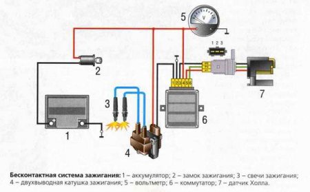
Plate - modulator:
This is where the whole secret of the stable operation of the Jupiter engine with one Hall sensor lies.
In some cases, gaps in sparking are associated with an incorrect design of the curtain-modulator (magnetic flux contactor). Pay more attention to its position in relation to the sensor. In the open state, the shutter should not overlap either the magnet or the magnetic circuit (metal "beak" at the end of the sensor), in the closed state, the modulator should completely overlap both of them. Otherwise, the sensor will give out fuzzy signals that the switch will not be able to recognize, and this is fraught with gaps in sparking, therefore, malfunctions in the motor.
The modulator itself should be made in the form of a disk with a cutout made of steel 0.8-1.0 mm thick, as shown in the figure. The main thing is that the ratio of the periods of the closed state of the sensor to the open state is 2: 1 (this is a prerequisite for the accurate operation of the control chip of the switch). If the engine is 1-cylinder, then the angle of the notch in the modulator should be approximately 120 degrees, if the engine is 2-cylinder, then the angles of the notch should be 60 degrees. It is also important to note that the minimum cutout width is 11mm. When setting the ignition timing, remember: the spark strikes when the modulator "opens" the sensor.
Before installing the BSZ, make sure that there are no excessive backlash in the generator shaft. This "carrier" of the curtain must fit into the axial run up to 0.35 mm, and its swing in the transverse plane is limited to 0.5 mm. The modulator petals walking in excess of these norms will not fit into the narrow slot of the sensor and will smash the fragile plastic housing of the Hall sensor to smithereens. The bumpiness is most often caused by wear of the generator bearings - change them without hesitation, especially since contact ignition is also not “friendly” with backlashes and will not be able to work clearly.

Setting:
At first I had difficulty adjusting the ignition timing. You can't go into electronics with a "dial" light, traditional for setting contacts. A voltmeter came to the rescue - I'll tell you how to use it.
I advise you to use a device with a scale of at least 15V and an internal resistance of 10-50 kOhm. Connect it to the terminals of the Hall sensor: place the positive wire on the contact No. 2, and the negative wire on the No. 3.

Set the piston of any cylinder to the position corresponding to the moment of sparking. Turn on the ignition and turn the modulator (in the direction of rotation of the crankshaft) until the voltmeter readings change. The discharge moment on the spark plug corresponds to a voltage jump in the sensor from tenths of a Volt to a value close to the onboard power supply of a motorcycle. Having "caught" the spark without knocking down the position of the shutters, fix the modulator on the generator shaft with a mounting bolt.
I must warn you that when adjusting the ignition, be sure to short-circuit the high-voltage wires to the engine housing or "load" them with candles. The operation of the coil with a broken secondary circuit leads to overload and damage to the BSZ. For the same reason, it is impossible to "muffle" the engine or one of its cylinders by removing the spark plug caps.
If you want to visually verify the presence of a spark, do it as follows. Fasten the tested wire (for the insulated part) 5-8 mm from the motor housing, turn on the ignition and press the kick. Do not try to fix the wire with your hands - it will jump out so that sparks fall from your eyes. However, this effect is also indisputable proof of the ignition efficiency.
Having set the lead once, you will forget about the voltmeter for a long time. Check the Hall sensor in a manner similar to the "angle" setting. But it is not necessary to rotate the crankshaft - it is enough to insert a steel plate into the sensor slot, for example, a screwdriver tip. A serviceable Hall with an "open" passage gives out 0.2-0.4 V, close the "damper" - the voltage in the circuit must be at least 7 V.
Operation and problems:
For some reason, many are sure that the same 12 volts from the switch are supplied to the red wire of the sensor, which "feeds" it, and based on these considerations, the sensor is connected not to the switch connector, but to the motorcycle's on-board network. The voltage there, of course, is the same, but it is only passed through the sensor protection system against voltage surges, which makes its operation clearer and more uninterrupted.
Now about the switches. Devices are not simple, expensive and not repairable, they do not forgive incorrect connection. It is much cheaper to buy a ready-made “switch-sensor” harness in a store (especially since it costs about 60 rubles) than to change a damaged “brain”. There is not enough space on the motorcycle, hands are itching to remove the radiator from the switch. This must not be done, since within ten minutes the switch will overheat and "die".
Another good piece of advice: if you have undertaken to redo the ignition, then all the parts should be "from the same bed" (sensor, switch, harness and coil). It is better to take a coil for 1-cylinder apparatus 3112.3705 from front-wheel drive "Zhiguli", and for 2-cylinder ones - two-spark 3012.3705 (from a modern "Volga" or "Oka"). Do not check the spark between the high-voltage wire and "ground", look at the spark only on the spark plug (which should have good contact with "ground" at the time of testing). If you take the wire too far from ground, the voltage in the secondary winding of the coil, trying to break through the excessive air gap, will exceed reasonable limits, and a spark will slip through the inside of the ignition coil and disable it. But since the coil is essentially a transformer, the voltage will rise in the primary winding too. And this may not withstand the output transistor of the switch. If it "burns out", the switch cannot be restored.
When writing this article, materials from the "Moto" magazine were used
BSZ on IZH Jupiter
Electronic ignition of a motorcycle "IZH-Jupiter" with one Hall sensor.
Of the many useful redesigns and improvements, contactless electronic ignition will bring the greatest benefit. The point is not at all about a powerful spark, but about the fact that the mixture ignites on time. As you know, the main bearings on the Jupiter crankshaft axle shaft are put on by hand and without the slightest effort. Among other things, the bearing itself often has a play of the order of a few hundredths of a millimeter. Add to this company of unfavorable circumstances the large cantilever of the breaker cam, add up all these backlashes and radial beats. Get a nightmare! After some 10,000 km, the spread of the ignition timing due to crankshaft bump will be about 4 mm from the set value. What kind of precise engine operation can we talk about here?
In a contactless system, due to the lack of a mechanical connection between the rotor and the sensor, the play of the crankshaft axle shaft practically does not affect the moment the spark appears. The engines improved in this way became faster in the entire rev range, and the nature of their work turned out to be softer - due to the synchronization of the ignition of the mixture in both cylinders and the absence of detonation. By the way, the engine operation without detonation significantly increases its resource.
I put BSZ on my Jupiter, really fiddled with the installation, but it was worth it. I forgot what kind of stumbling ignition is in general (it’s not even afraid of dampness!), The engine began to work much smoother, smoother, dynamics improved, at speed the engine became much more sensitive to gas, idling was smoother and more stable. Starts up even with a decently drained battery with "half a kick"
^ What we need:
AND). Switch for contactless electronic ignition of a front-wheel drive vehicle "VAZ". Take the switch only in its original packaging in an AUTOMATIC STORE and with a guarantee of at least a year. average price RUB 350
B). Hall Sensor. Anyone from the same "VAZ", but also in the original packaging. The price is about 80 rubles.

IN). The ignition coil is two-pin, from the "Gazelle", but always from the 406th engine. You can take it from "Oka" for electronic ignition, there is absolutely no difference between them. (350 rub.)

D). Two silicone armored wires with rubber caps. Price from 100 rubles.
D). Hall sensor modulator and mount
They need to be sharpened by a turner. I do not recommend using an ordinary plate as a modulator. Its width is no more than 12 mm, which is not enough for the full energy storage of the coil. Of course, you can put it on, but you will not see more than 4000 rpm as your ears

E) We also buy instant diagnostics of MD-1 and emergency ignition of AZ-1 in a car shop. Prices for these devices are around 70 rubles for each

G) A set of wiring with connectors for contactless ignition VAZ price 80-100 rubles.

^ Well, have you bought everything and are ready to collect? Go...
The old ignition system (breaker contacts, ignition coils, capacitors, armored wires) is completely abolished. The switch is installed in the right glove compartment, the ignition coil is under the tank. Unfortunately, the reel doesn't have any holes or mounts for the bracket, so I couldn't think of anything better than winding it to the frame with a thick layer of copper wire.
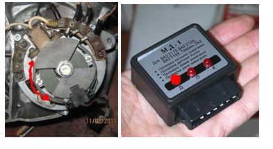
We assemble the modulator and the DX mount, install everything on the standard generator, as shown in the figure:


The main thing during installation is to maintain the diameter of the modulator (the gap between the lower partition of the hall sensor and the modulator should be 1-1.5 mm) and the alignment of the mounting (the radius of the modulator should run along the axis of symmetry of the hall sensor). I also screwed the sensor connector to the side of the generator. After installing the hall sensor, we put on the modulator and see if it falls into the sensor slot. If not (and this is 90%), then we put spacers on the stud. After that, as the required gap is maintained, we put the grower and tighten the modulator with the standard generator bolt.
Next steps:
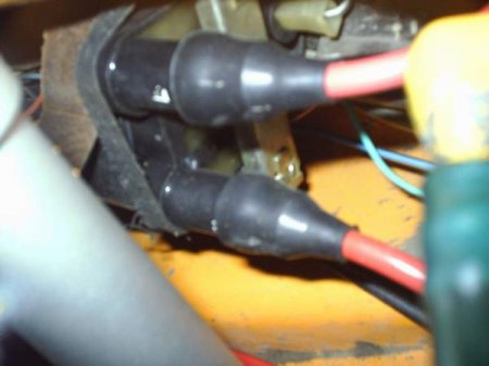
We put on rubber caps on the armored wires, and the armored wires themselves (they must have special copper tips) are inserted into the candlesticks and into the coil. Pull the aforementioned caps on top. If you don't, you will push the motorcycle on foot when riding in the rain. Immediately insert the candles into the tips and ensure reliable contact with the "mass" of the motorcycle.
With the help of wiring, we simply connect the switch, the hall sensor, the coil and the AZ-1 with wires. (The AZ will have to be soldered and a switch button must be connected to its 1st connector so that a constant spark is turned on at our discretion). Moreover, we "pack" the wires into a PVC tube or simply wrap them with electrical tape. Of all the purchased heap, we need to display only the general "plus" of the system on the "panel". We "lead" it to the right "Move-stop" switch, having previously unsoldered the standard wires from it. We connect the second wire from the onion switch to terminal "1" of the ignition switch (the second wire from the same terminal goes to the signal).
Here is the actual connection diagram:
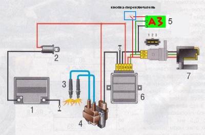
1 battery
2 ignition lock
3 spark plugs
4 ignition coil
6 switch
7 Hall sensor
^ Well, everything seems to be assembled, you can customize it.
Performance check - we throw both candles on the cylinders, take a screwdriver (you can also use a manufactured modulator, insert it into the slot of the hall sensor and pull it out. At this moment there should be a spark (on both candles).

If after the above steps there is still no spark, check the correctness of the connections. I assure you that when using "non-left" components, everything should work as it should.
Now setting. We adjust the piston of one of the cylinders to the TDC, move it back 2.8 mm (when using AI-92 gasoline, it is desirable to reduce the angle to 2.5 mm). Next, we connect the MD-1 instead of the switch and begin to slowly twist the DX mount around the modulator (clockwise). As soon as you "catch" that the "D" indicator is on for instant diagnostics, fix the DX mount in this position.
Well, what can I say, we screw in the candles, put on the candlesticks, reconnect the switch, pump up gasoline ... You have BSZ. And when the AZ button is turned on, you can now start the motorcycle even without a kick starter, although driving in the AZ mode (constant spark) is recommended only if the HH fails and at a speed of no more than 90 km / h
^ Finally, a few tips:
1. Do not allow BSZ to work with the battery disconnected. Make sure the connections are secure to avoid sudden disconnection of the battery.
3. If, when installing the generator cover, the BSZ completely refuses to work, reverse the brushes of the generator excitation winding.
4. Check the voltage of the electrical system with the engine running. A strong scatter of parameters can affect the operation of the BSZ, or even disable it (if the voltage is exceeded 16 V).
Well, that's probably all. Good luck.