Voltage regulator
OPERATION OF THE VOLTAGE REGULATOR
Technical specifications
Adjustable voltage at 50 ° C. AT
at the second stage ...................., .. 14.2 ± 0.3
at the first stage lower than at the second ... by 0.7 V
Temperature compensating resistor ...: ......... 19 ohm, 6 W
Additional resistor ................. 5.5 Ohm, 25 W
To regulate the voltage in on-board network The car uses a two-stage vibration voltage regulator of the PP-380 type. It is installed in the engine compartment on top of the left wheel mudguard. The voltage generated by the generator ^ is mainly dependent on the rotor speed of the generator. Since the generator is powered by an engine running on different speed modes, then the rotor speed, and, consequently, the generator voltage can also vary within significant limits, if you do not take protective measures, then when high frequency rotation of the generator rotor, the voltage in the vehicle's on-board network can be significantly higher than the nominal, which will damage all electricity consumers. Therefore, in order to ensure the normal operation of electrical equipment and the required charging mode battery, apply a voltage regulator. It maintains the voltage generated by the generator at a constant level (13-14 V) over a wide range of rotational speeds of the generator rotor. The spare parts also receive a non-contact electronic voltage regulator type 121.3702. It can be installed instead of the PP-380 regulator without any alterations in the car's electrical equipment. The 121.3702 regulator maintains the voltage at the level of 13.4-14.6 V in a wide range of generator rotor speeds and at temperatures from -40 to + 80 ° C.
The voltage regulator is an electromagnetic relay. Like every relay of this type, it has a magnetic system consisting of a cylindrical core and a U-shaped yoke 9, a coil with a winding 6 on a plastic frame, an armature 7 with a movable contact and two posts 4 and 5 with fixed contacts. The legs are attached to the yoke with a screw and nut and are isolated from it and between themselves by plastic spacers. The slots in the posts allow you to move them up and down when adjusting the regulator.
The upper and lower contacts of the armature, in combination with the contacts of the posts, form two pairs of contacts - upper to lower. The spring armature is pressed against the contact of the upper rack, i.e. the top pair of contacts is normally closed. By bending the lower spring bracket, you can change its tension and thereby adjust the amount of stress at which the upper pair of contacts will open. Opening and closing the upper pair of contacts provides the first stage of regulation, and closing and opening of the lower pair of contacts provides the second stage of regulation. A yoke with a core is mounted on a stamped steel base 10 on a plastic gasket. Under the base, on an insulating gasket, there are temperature compensating 1 and two additional resistors 2 connected in parallel with a total resistance of 5.5 ohms. The resistors are wound with nichrome wire on a fiberglass cord impregnated with organosilicon varnish. The bottom insulating pad is also the body of the plug connector, which houses the plugs "15" and "87".
Choke 3 serves to reduce sparking between the upper pair of contacts when the regulator is operating. It is a coil of copper wire wound on a plastic frame. 8 coil is inserted into a steel core, which at the same time is a conductor of current from plug "15" to pole 5. For smooth operation regulator, it is necessary that its internal cavity is reliably isolated from environment... Ingress of moisture and various substances under the cover leads to contamination, burning of contacts and disruption normal work regulator. Therefore, the top of the regulator is tightly closed with a steel cover 8 with a polyurethane gasket, and the materials used in it are checked for the absence of outgassing.
Relay control lamp battery charge
Technical specifications
Contact opening voltage *, V ............... 5,3 ± 0
Contact closure voltage ", V ................. 0.2-1.5
Winding resistance at 20 ° С, Ohm ................ 29
Relay 20, type RS-702, is designed to turn on the control pump in the instrument cluster when the generator voltage is insufficient to charge the battery. Repeat installed engine compartment on the top of the right wheel mudguard. The relay consists of a yoke, a steel core with a winding, an armature and a stand with a fixed contact. The yoke with a core and a stand are installed on a ge-tikaks base. The armature is attached to the yoke shelf using a spring steel plate, which presses the armature contact against the post contact, and therefore the relay contacts are normally closed.
Fig. 1
Fig. 2
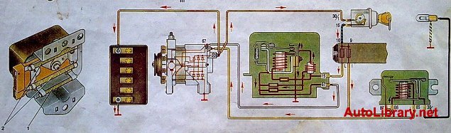
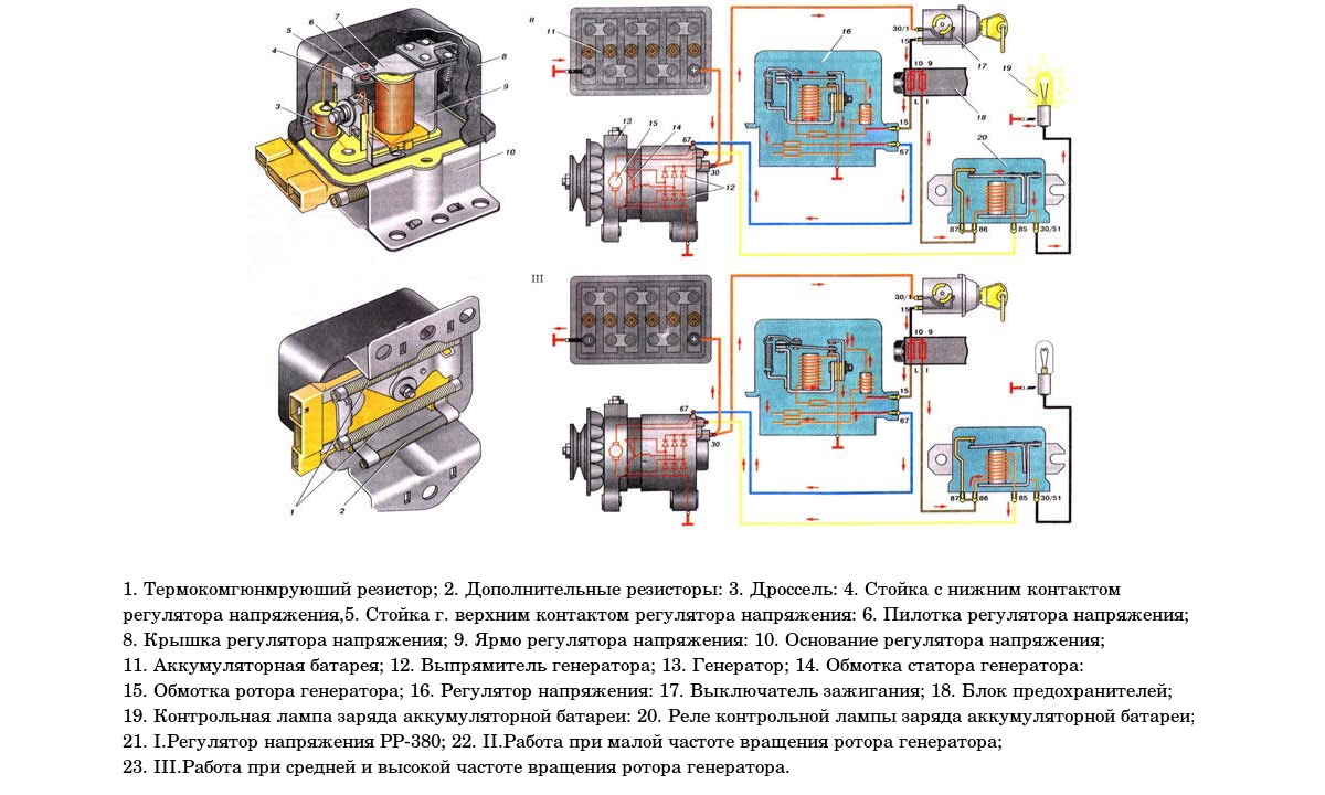
Figure: 1.2. The scheme of the voltage regulator.
1. Thermo-compensating resistor; 2 ... Additional resistors; 3 ... Throttle; 4 ... Rack with the bottom contact of the voltage regulator; 5 ... Rack with the top contact of the voltage regulator; 6 ... Voltage regulator winding; 7 ... Voltage regulator armature; 8 ... Voltage regulator cover; 9 ... Yoke voltage regulator; 10. Base of the voltage regulator; 11 ... Accumulator battery; 12 ... Generator rectifier; 13 ... Generator; 14 ... Generator stator winding; 15 ... Generator rotor winding; 16 ... Voltage regulator; 17 ... Ignition switch; 18 ... Fuse box; 19 ... Battery charge indicator lamp; 20 ... Battery charge warning lamp relay; I... RR-380 voltage regulator; II... Operation at low rotational speed of the generator rotor; III... Operation at medium and high rotor speed of the generator.
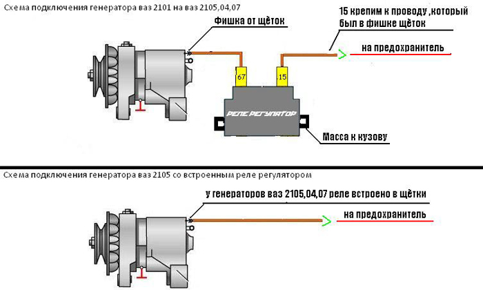
A relay-voltage regulator of the VAZ 2101 generator is used to maintain the voltage level in the vehicle within the technically permissible value. A 2-stage vibration device RV-380 copes with the task. It is mounted in the area of \u200b\u200bthe upper part of the mudguard above the left wheel. The intensity of the regulator is directly dependent on the generator rotor speed.
The faster it spins, the more voltage is generated. A technically sound regulator quickly extinguishes the resulting voltage surges. The driver is informed about this by the stability of the sensor readings. dashboard VAZ 2101. If the readings become unstable, this indicates the need for a technical inspection.
Physical characteristics of operating parameters
The original VAZ 2101 generator supports the specified parameter at around 13 to 14 V. This device is used only with a wide range of car rotor speeds. As an additional line of defense for consumers of electricity 2106 or 01, a contactless voltage level regulator is used - 121.3702. If necessary, it will replace the RV-380, and the VAZ charging circuit will not be affected.
An additional fuse holds the voltage at 13.5 to 14.6 V over a wide rotor range. Rest specifications look like this:
- operating temperature range: from -40 to + 80 ° С;
- additional resistor resistance: 5.5 Ohm (25 W);
- resistor with thermal compensation function: 19 Ohm (6 W);
- voltage regulation at stage I: 0.7 V;
- voltage regulation at stage II: from 14.2 to 14.5 V.
In terms of structure, the voltage regulation of the VAZ 2101 is carried out using a variable magnetic field. In case of occurrence technical malfunction it is necessary to carry out diagnostics and replacement, if necessary. Experienced drivers do not recommend operating a car if the VAZ 2106 generator does not balance power surges.
Correct repair and replacement of the device
Maintenance is done in the garage, even if the driver does not have much experience in auto locksmithing. First you need to turn off the engine and remove the terminals from the battery. Further repairs are connected with the careful removal of two nuts of the regulator itself with an “8” spanner. As soon as the device came out of the grooves, you must smoothly disconnect the 2 wires.
It is recommended to inspect the alternator pulley and its housing for traces mechanical damage or short circuit. If there are any, then it makes no sense to repair it. Firstly, it will take a lot of time, and secondly, the battery charging process will not be complete. In this case, it is more expedient to purchase a new regulator.
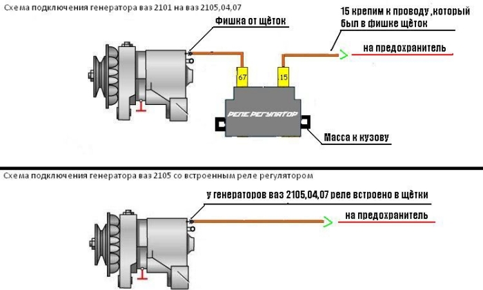
It is attached to the mudguard with fixation with 2 bolts. The following recommendation will help to correctly connect the generator to the VAZ: the orange wire is connected to output 15, and the gray wire to output 67. Not to get confused here will help the connection diagram of the VAZ 2106 generator, which should be at hand. You must use the option supplied with your passport. He will tell you in detail how to connect the generator.
Without fail, before turning the key in the ignition lock, you must make sure that the contact between the "ground" and the body 2101 is reliable. If this is not done, then the service life of the voltage regulator 2101 will be short. Overcharging will literally burn your device.
Analogs or original spare parts? There is no consensus among drivers about which parts are best to use. The cost of a new voltage device is about 100 rubles, and the connection of the generator itself does not require professional skills. Despite this, it is better not to risk it, because uncompensated voltage surges will harm all the electronics in the car.
Optimizing device performance
There is a widespread belief among drivers that tuning the voltage regulator improves the driving performance of the car. First of all, we are talking about large speed ranges without prejudice to the equipment of the machine. There is some truth in such a statement, because the charging relay is really responsible for correcting all voltage surges at varying speeds. But it will not be possible to significantly increase the indicator.
In addition to replacing the generator, it will be necessary to update the wiring, making it resistant to heavy loads.
Following it, the rotor will require updating for charging the VAZ 2106. That is why it is recommended to evaluate the financial capabilities and feasibility of such updates.
Regulation of voltage drops in the car network is performed by a special relay. The slightest deviations in its work negatively affect the running parameters of the machine as a whole. In this regard, drivers are recommended to regularly carry out preventive inspections.
The VAZ charge relay can be called a kind of switch that is activated at the moment when the starter, generator, etc. begins to consume more than stated current. However, it often happens that the regulator itself needs help! It is quite possible to try to diagnose the cause of the problem, both in a UAZ car and in a VAZ, on your own, but only a professional should be involved in the repair. The process does not tolerate amateurishness! By making a few mistakes, you can make the charging system completely unusable. And it is very difficult to restore the circuit.
What does a relay consist of?
The charging relay has a fairly simple scheme implementation, which will probably be clear to those who have already encountered similar problems. The minimum of elements, the maximum performance of each of them. Within a few hours, the diagram can be studied up and down!
The device includes:
- an electromagnet wound on a core coil made of magnetic material;
- anchor - a special plate responsible for managing contacts;
- switch - an element responsible for opening and closing contacts.
On VAZ 2106 cars, 2 types of relays are used:
- Non-contact. Relatively new unit, which does not require settings and adjustments from the driver's side. It rarely breaks down and, if necessary, can be easily replaced with a similar component, which is produced to this day.
- Magnetic regulator. An old-style device that has quite a few complaints. It is not possible to find it on free sale today, but such a model is quite realistic to replace it with an updated version.
Relay interchangeability is one of the best opportunities that the company that created the VAZ 2106 could provide to drivers.
Thus, gradually improving the components, the owner will be able to use any vehicle, the repair of which, in comparison with foreign equivalents, will cost minimum amount... If you want, the VAZ 2106 can be slightly improved. And for quite real money.
Possible problems and diagnostics
There are many reasons why a 702-coded proximity relay or its magnetic equivalent will fail.
The most common ones are:
- Worn out generator brushes. Over time, the length of the brushes may decrease, which inevitably leads to complete absence or partial loss of charge. If you notice a problem, be sure to check the length of the brushes. It should not be less than 12 mm! If there is even a small deviation from the specified parameter, it requires immediate replacement.
- The problem with the diode bridge. The burnout of even a few diodes is fraught with a weak battery charge. Diagnostics of the bridge in a service station is required!
- The integrity of the fuses. Finding a malfunction in this system is not an easy task, however, after spending a few hours, you will definitely find it! The most radical measure is the replacement of fuses, which can be avoided in the vast majority of cases.
- Oxidation of the terminals. You can clean them yourself by using water with soda diluted in it. Just a few minutes, and the VAZ charging system will function like new.
Such problems are among the most common and occur in the vast majority of cases. If it was not possible to identify the problem on your own, it is better to contact a specialist who will probably figure out how to resurrect the charging relay.