The gearbox synchronizer is a mechanism designed to equalize the speed of the gearbox shaft and gear. Today almost all mechanical and robotic boxes gears are synchronized, i.e. equipped with this device. This important element in the gearbox makes shifting smooth and fast. From the article we will learn what a synchronizer is, what it is for and what the resource of its operation is; we will also understand the structure of the mechanism and get acquainted with the principle of its operation.
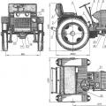
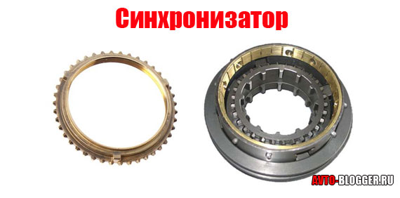
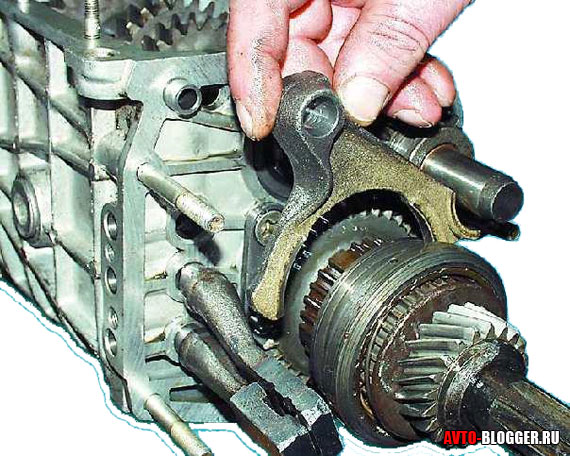
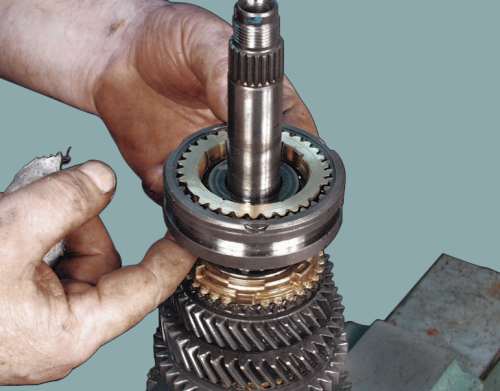
General view of the synchronizer
All gears of modern gearboxes of passenger cars are equipped with a synchronizer, including gear reverse... Its purpose is as follows: ensuring the alignment of the speed of the shaft and gear, which is a prerequisite for shockless gear shifting.
The synchronizer not only ensures smooth gear changes, but also helps to reduce noise levels. Thanks to the element, the degree of physical wear of the mechanical parts of the box is reduced, which, in turn, affects the service life of the entire gearbox.
In addition, the synchronizer has simplified the principle of gear shifting, making it more convenient for the driver. Before the advent of this mechanism, gear shifting took place using a double clutch release and shifting the gearbox to neutral.
Synchronizer design
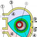
 Synchronizer device
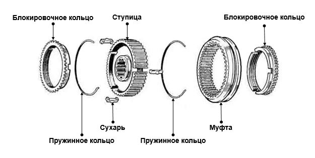
 The synchronizer consists of the following elements:
- hub with breadcrumbs
- clutch
- locking rings
- friction cone gear
The basis of the assembly is a hub with internal and external splines. With the help of the first, it is connected to the gearbox shaft, moving along it in different directions. The hub is connected to the coupling by means of external splines.
The hub has three grooves at 120 degrees to each other. The grooves contain spring-loaded crackers, which help to fix the clutch in a neutral position, that is, at the moment when the synchronizer is not working.
The clutch is used to provide a rigid connection between the gearbox shaft and the gear. It is located on the hub, and from the outside it is connected to the transmission fork. The synchronizer locking ring is necessary to synchronize the speed using frictional force, it prevents the clutch from closing until the shaft and gear have the same speed.
The inner part of the ring is cone-shaped. To increase the contact surface and reduce the effort when shifting gears, multi-cone synchronizers are used. In addition to single synchronizers, double synchronizers are also used.
The double synchronizer, in addition to the tapered ring that is attached to the gear, includes an inner ring and an outer ring. The conical surface of the gear is no longer used here, and synchronization occurs through the use of rings.
The principle of operation of the gearbox synchronizer
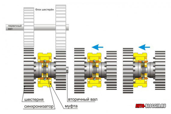
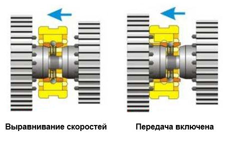 Synchronizer operation diagram
 In the off state, the clutch takes the middle position, and the gears rotate freely on the shaft. In this case, the transmission of torque does not occur. In the process of choosing a gear, the fork moves the clutch towards the gear, and the clutch, in turn, pushes the locking ring. The ring is pressed against the pinion cone and rotates, making further advancement of the clutch impossible.
Under the influence of friction force, the gear and shaft speeds are synchronized. The clutch moves freely further and rigidly connects the gear and the gearbox shaft. The transmission of torque begins and the vehicle travels at the selected speed.
Despite the rather complex structure of the node, the synchronization algorithm lasts only a few fractions of a second.
Synchronizer resource
In case of any malfunctions associated with gear shifting, first of all, it is necessary to exclude problems with the clutch and only then check the synchronizer.
You can independently identify a malfunction of a node by the following signs:
- Transmission noise. This may indicate a curved locking ring or a worn out cone.
- Spontaneous shutdown of gears. This problem can be associated with the clutch, or with the fact that the gear has outlived its resource
- Difficult inclusion of the transfer. This directly indicates that the synchronizer has become unusable.
Synchronizer repair is a very laborious process. Better to just replace worn out mechanism on new.
Observance of the following rules will help to extend the service life of the synchronizer and the gearbox as a whole:
- Avoid aggressive driving style, abrupt starts
- Choose the right speed and gear
- Timely conduct maintenance Checkpoint
- Timely change the oil intended specifically for this type of gearbox
- Fully disengage the clutch before shifting
A synchronizer is a device that is part of the gearbox of many cars (including VAZ 2110), and is a part of it, which allows you to make the gear shifting process smooth, and this happens by aligning the speeds of rotation of the gear and the clutch, thereby eliminating shocks at the moment of switching and protecting from rapid wear of the gear teeth.
The synchronizer consists of a hub, which is rigidly fixed to the shaft, movable relative to the hub of the movable coupling, gears, locking rings and a holder of crackers. Watch a video about the principle of operation of a manual transmission:
Possible malfunctions:
With prolonged, and most importantly, very frequent use of the gearbox (this happens when driving on difficult roads, when you often have to switch gears), even if you use it correctly, noise may appear at the time of gear shifting, clearly indicating a synchronizer malfunction. Most often, this breakage indicates the wear of the thread of the canonical surfaces of the locking rings, the disappearance of the gap between the end face and the crown of the gear, or the absence of friction between the coupling cones.
Repair of a synchronizer is a complete disassembly with the subsequent replacement of all damaged parts.
For repairs, you may need a flat-blade screwdriver with a sturdy handle and fine-lipped pliers.
Repair of the VAZ 2110 gearbox synchronizer:
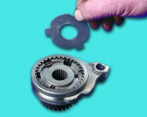
1. Before proceeding with disassembly, it is necessary first of all from the secondary shaft.
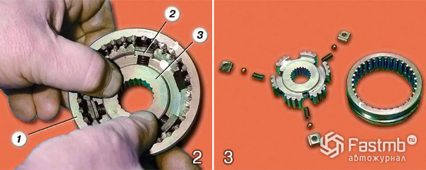
2. It is very important at the very beginning to mark the location of the coupling (3) in relation to the hub (1) with a marker or chalk. Then carefully remove the clutch from the hub. Remove with extreme care so that the crackers (2) together with the balls do not fly apart under the influence of the springs. Thoroughly rinse all removed parts in kerosene and lay out on a clean and free of litter surface.
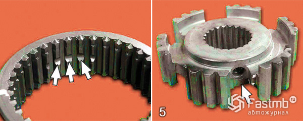
3. Carry out a careful and scrupulous visual inspection of all parts: splines, hubs, couplings (focusing your attention on the ends of its teeth) for chips and nicks. In addition, just as carefully inspect each cracker, ball and each spring - their physical condition should be ideal and they should not have any visible signs of damage and rough traces of wear, the springs should not be stretched or too compressed. It will not be superfluous to check the gap between the ends of the ring and the gear rim. If you find defects on any parts, replace them with new ones, but if there are so many defects that it is easier to replace the entire synchronizer, then it is best to do this.
4. After the performed repair and restoration measures, before replacing defective parts, lubricate them engine oil... Install the coupling back onto the hub using the previously set mark.
5. If the marks match, then by itself it will turn out that the grooves (there are three of them) on the coupling will coincide with the grooves of the hub.
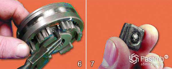
6. Then it is necessary to lubricate the retainer spring with lithol 24 and insert it into the hole of the hub groove.
7. Put a ball into the hole of the biscuit pre-lubricated with lithol.
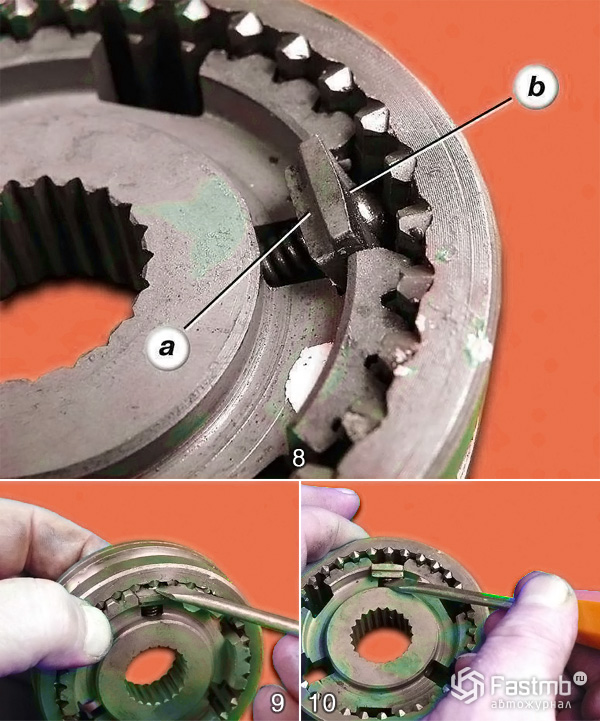
8. Insert a cracker with a ball into the groove of the hub, using a screwdriver, having previously compressed the spring, while the grooves (a) on the cracker should be outside, and the spherical (b) surface is turned to the coupling.
9. When installing the cracker, try to get the ball inserted into it into the grooves on the splines of the coupling, for this push it deeper.
10. Using a screwdriver, direct the spring into the hole in the cracker. The rest of the clips should be installed in the same way.
Video about disassembling and assembling the device:
Prevention:
As a rule, breakdowns and rapid wear of synchronizer parts are associated with rough work with the shift lever. To prevent this and extend the life of the synchronizer, gear shifting must be done smoothly, without jerking.
All modern mechanical boxes transmissions as well as robotic transmissions are synchronized. In such boxes, in order to engage the gear, the shaft and gear speed are aligned. Synchronization is provided by a device of the same name - a synchronizer. In addition to smooth gear shifting, the synchronizer reduces wear mechanical connection, noise when shifting and thus extends the life of the gearbox.
All gearboxes are equipped with synchronizers. passenger car, including reverse gear. The principle of operation of the synchronizer is based on the use of friction forces in the equalization of speeds. The higher the difference in the speeds of rotation of the shaft and gear, the greater the magnitude of the friction force must be to synchronize them. The fulfillment of this condition is achieved by increasing the contact surface area - by installing additional friction rings.
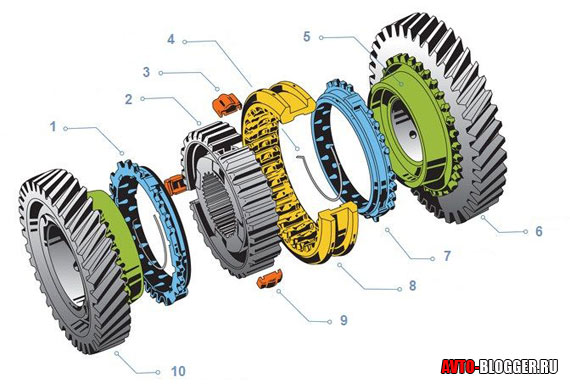
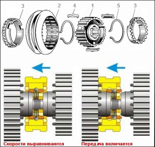
Consists of the following elements:
1.Lock ring
2.Nave
3. Sugar
4. Ring spring
5.Friction cone gear
6.Gear
7.Lock ring
8.Synchronizer coupling
9 Sugar
10.Gear
The hub is the structural basis of the synchronizer. It has internal and external slots. With the help of internal splines, the hub is connected to the output shaft of the gearbox and has the ability to axially move along it in different directions. External splines connect the hub to the engagement clutch.
Three grooves are made around the circumference of the hub at an angle of 120 °, in which spring-loaded crackers are installed. In the synchronizer, crackers are pressed on the locking ring when the gear is engaged and help to lock the clutch during the synchronization phase.
The engagement clutch (also called the synchronizer clutch) provides a rigid connection between the shaft and the gear. The clutch is mounted on the hub and has internal splines. An annular groove is made on the slots, in which the projections of the crackers are located. Outside, the synchroniser clutch is connected to the transmission fork.
The locking ring provides synchronization and prevents the clutch from closing until the shaft and gear speeds are equalized. WITH inside the locking ring has a tapered surface that interacts with the friction cone of the gear. Outside, the locking ring has slots, with which the engagement clutch is locked.
On the end surface of the blocking ring from the hub side, there are three grooves, into which the hub rusks enter. The grooves prevent the ring from rotating when it comes into contact with the friction cone (crackers rest against them). The size of the grooves is 1.5 times the size of the crackers. In some designs of synchronizers, on the contrary, projections are made on the blocking ring, and grooves are made in the hub.
To increase the contact surface, reduce the effort when shifting gears, multi-cone synchronizers are used: two-cone, three-cone. For example, in a three-cone synchronizer, in addition to the blocking (outer) ring, an inner and an intermediate ring is also installed. To prevent rotation, projections are made on the rings, which are fixed in the grooves of the gear and the locking ring.
Thus, three friction surfaces are created in a three-cone synchronizer: between the pinion cone and the inner ring, between the inner and intermediate ring, between the intermediate and blocking rings. Depending on the design, synchronizers with different numbers of cones can be installed in one gearbox.
Synchronizer operation
Synchronizer operation diagram
In the neutral position of the gear lever, the synchronizer clutches are in the middle position, the gears on the driven shaft rotate freely, the power flow is not transmitted.
When the gear is engaged, the fork moves the synchroniser sleeve from the middle position towards the gear. Together with the clutch, crackers move, which act on the blocking ring. The ring is pressed against the pinion cone. A frictional force arises on the surface, which turns the ring until the crackers stop in the grooves of the ring (the ring is locked from turning). In this position, the locking ring prevents further advancement of the synchronizer sleeve along the shaft axis, since the ends of the locking ring splines are located opposite the ends of the coupling splines.
Further, under the action of friction forces, the speeds of the gear and the driven shaft are synchronized. When the speeds are equalized, under the pressure of the clutch splines, the locking ring rotates in the opposite direction, the clutch lock is removed, the clutch splines pass freely to engage with the gear rim. There is a rigid connection of the secondary shaft of the gearbox and the gear.
Despite the multitude of operations, the entire process of synchronization and transfer engagement takes a split second.
A question from a reader:
« Hello, I am a novice driver and your answer is very important to me. Recently I bought a used VAZ 2110. After some time, the transmissions began to turn on poorly (or not at all), a crunch was heard when switching. I went to the service station there, the box was disassembled and told - that you need to change the synchronizers! You can't do without it! Moreover, the master advised (if the gearbox was disassembled), immediately change the bearings and even one drive shaft, but this can wait. In general, the question is - what are these synchronizers, and do you need to change all these elements that he named, or can you still drive them? How long can they still pass? Thank you Sergey, I look forward to your advice, Maxim»
Maxim I understand your question, in general the gearbox on our VAZ is one of the reliable units of the entire car. Let's get it all on the shelves ...
If you have any breakdowns, then most likely the mileage is already very large, or the care of this manual transmission was not correct, for example, the oil was not changed in time, or it was gone. In general, if there is such a thing - that the gears do not switch, then the workshop workers are right, but let's start with the definition.
Synchronizers (applied to transmission) Is a device that synchronizes the speeds of the shaft and gears. Thus, shifting becomes fast and smooth, without unnecessary noise and "crunch", and these devices also reduce breakdowns caused by incorrect shifting and wear of parts.
In simple terms, it becomes clear that the synchronizer just kind of aligns the gear and the shaft at the right moment, so they engage and then the required rotation continues. Previously, there were transmissions without them, but switching on the gear was not an easy task, it was accompanied by a crunch, and it was not always possible to turn it on the first time. It should be noted that such devices are installed not only in forward gears, but also in reverse gears.
IN modern world, almost all are synchronized mechanical transmissions, as well as some "robots", because their "core" is practically the same with the manual transmission.
Device
It is really not simple, but I will try to explain everything very simply. Synchronizers are installed on the main gears, they allow you to smoothly engage gears. They are usually made of stainless metals such as brass and its alloys. The choice of material must be approached carefully, you need to take a knowledgeable person with you. Watch this video.
This element consists of several parts.
1) Main locking ring
2) Hub housing
3) The gear wheel of the so-called "biscuit"
4) Annular spring
5) Cone friction gear
6) Main gear wheel
7) Another lock ring
8) The clutch of the synchronizer itself
9) Another "cracker"
10) Gear, one more transfer
It should be noted that in the gearbox one synchronizer serves two gears at once, that is, it works on two gears, which can be seen from the diagram.
The main working element is undoubtedly the hub, as you can see it has internal and external engagement, with the help of the lower "teeth" it can be connected to the secondary shaft and moves along it in different directions. But the outer "teeth" of the hub connect it to the clutch.
Along the circumference of the hub, at angles of 120 degrees, there are three main pairs in which spring-loaded crackers are placed. It is they who press the locking rings when the gear is engaged and contribute to the short blocking of the clutch, which is necessary precisely for synchronizing the engagement.
The inclusion clutch (it is she who translates the gears), provides a rigid connection of the shafts and gears of the gears. It "sits" on the hub and is connected to it using internal splines. There is a groove on the clutch housing, it is through this groove that it is transferred in the right direction, as you probably already guessed - this is done using the gearshift lever, which is connected to a special fork, which in turn goes in this groove.
The locking rings perform the function of synchronization, they do not prevent the complete stop of the coupling, but only align the speeds of the shaft and gear. The body of such rings has a tapered surface that interacts with the pinion cone. The outer part has slots, with their help, the coupling is locked. At the end of the ring, three grooves are made into which the "crackers" go. With this design, the ring does not spin and does not slip when in contact with the friction cone.
To increase reliability, as well as for smoother switching, multi-cone synchronizers are used, for example, two or three cone.
The three-cone variants are the most difficult, but also more durable, they are mainly used in automatic boxes - robots, and also stand in the design of some foreign cars.
Principle of operation
The work takes place in a split second, but the process is really difficult to describe in a few words.
Neutral - The couplings are not meshing and the gears rotate freely.
Engaging the gear - we move the lever to the "speed" we need, accordingly it "leads" through the fork and "slot" of the engagement clutch to the desired position. Crackers begin to shift, which then act on the locking rings, and it, in turn, goes to the gear cone. As you can imagine, friction begins between the cones, which turns the ring until it practically stops. After that, the gear is put on the shaft, that is, synchronization occurs.
The engine is rebuilt to new revs, and we get either acceleration or traction.
It may be a little confusing, then watch this video.
Malfunctions and methods of their elimination
The main malfunctions of the manual transmission are due to high wear or misuse... As a rule, shafts and gears are quite durable products, so it is extremely difficult to break them, and they practically do not suffer. However, the weak link is precisely the synchronizers, because they have the largest number of small, easily "erased" elements. If the transmission oil is poor, it cannot be guaranteed to lubricate all parts, so increased wear occurs. Thus, the synchronizer rings are the first to suffer. This is manifested:
- Increased crunch when switching
- Difficulty shifting gears, or not included at all
- Spontaneous disengagement of the transmission, for example - when the speed is dropped, the clutch itself may already be damaged
In any of these cases, the synchronizer or its rings (which is most often the case) is covered, or you need to completely check the coupling for wear.
The repair is complex and requires a sufficiently high qualification of the master, I would not allow anyone to make my manual transmission, because wrong actions entail repeated repairs, and this is removing the box, etc.
In your case, the wizard outlines the replacement of other rubbing elements, such as bearings. This is true, because your synchronizers are out of order, and this indicates a high wear of the entire mechanism. So my advice to you - if you plan to drive this car for a long time, then change everything, as the master tells you!
And that's all for me, read our AUTOBLOG.
The appointment of the checkpoint is known to anyone who has ever driven a car. However, both its structure and the principle of operation often remain a mystery to many. In general, this may be correct, in any case, such an approach has a right to exist, nevertheless, without engaging in a detailed study of the box, it is worth touching on such an element of it as a synchronizer.
What are gearbox synchronizers for?
A manual gearbox changes the torque coming from the internal combustion engine to the wheels of the car, for which various gears are used, located inside the box. The structure of such a mechanism, as well as how it all looks, helps to understand the figure below:
The principle of operation of such a gearbox is quite simple - when you change the position of the gearshift knob, the gears in engagement change, and each pair of such gears has its own characteristic. Its change leads to a change in the magnitude of the moment transmitted to the wheels. Thus, any manual transmission works, including the VAZ 2109.
However, an interesting moment arises - the gears that must engage have different angular velocities, and it is quite difficult to combine them just like that, while the probability of destruction of the gears and other elements of the box increases.
The gearbox synchronizer is designed to solve this problem. Experienced drivers remember that earlier, before synchronizers were used in the gearbox design, special techniques had to be used when changing gears. Switching from low to top gear, was carried out using a double squeeze. First, the gearbox was shifted to neutral, after which the clutch was released.
Then the clutch was squeezed out again and the driver shifted into gear. Exposure in neutral allowed the gears to equalize the speed, and also to avoid grinding when shifting gears.
When shifting from high to low gear, a double squeeze was used, and even with a rebase. At the same time, the clutch was squeezed out, the gearbox was switched to neutral, the clutch was released, the gas pedal was slightly pressed, which led to alignment angular velocities gears, and after that the clutch was pressed again, after which the gear was engaged.
As you can see from the above description of the driver's actions, such switching is quite tedious and takes a long time. Here is the synchronizer and allowed to greatly simplify the whole procedure.
Gearbox synchronizer operation
What is such a device, the composition of the synchronizer and its principle of operation will help to understand the figure. We will not consider the purpose and number of small parts included in the synchronizer, it is enough that they are shown in the figure, but we will try to understand how everything works. It's just interesting, all cars use the same principle according to which the synchronizer works, including for the VAZ 2109.
Thus, it can be noted that the synchronizer device includes:
- hub 1;
- clutch 2;
- locking ring 3;
- crackers 4;
- wire rings 5.
At the moment of gear shifting, clutch 2 moves towards the desired gear. On the conical part of the gear, due to the different angular velocities of the gear and the coupling, a friction force appears between them, due to which the locking ring 3 turns to the stop. When the teeth of the locking ring and the coupling are opposite, the movement of the coupling stops.
An equalization of speeds occurs, while the friction force that initially displaced the locking ring disappears, and it returns to its original position, and the clutch 2 passes through the teeth of the locking ring and is connected to the rim of the included gear. Thanks to the rusks, the clutch is rigidly connected to the shaft, which means that the gear is engaged and the synchronizer has worked out the whole procedure, ensuring a quiet engagement of the gear.
Gearbox synchronizer, care, operation
A device like a synchronizer should be accepted with gratitude. Of course, there is nothing difficult in shifting gears using a double squeeze, it is still used on some cars. construction equipmentwhere, according to the operating conditions, the use of a synchronizer is excluded. But its introduction into the design of a passenger car, including the VAZ 2109, made it much easier to control, which made the car more affordable.
How sometimes it is unpleasant to realize that the box is broken. You understand this when gear shifting starts to rattle or its other defects appear. Most often, external signs of malfunction or severe wear of synchronizer parts, including for the VAZ 2109, can be:
- noise during gearbox operation;
- difficulty shifting gears
- self-switching off of gears.
Of course, the appearance of such defects may be due to other reasons, but more often it is the synchronizer, failure or wear of its parts that leads to such phenomena. This is true for any car, and the VAZ 2109 too.
Basically when happens right choice travel speed used desired gear, timely carried out and applied the right oil, the gearbox and synchronizer serve for a long time, which is also true for the VAZ 2109.
A device such as a synchronizer allows you to switch gears in a gearbox in a short time without noise and grinding, ensures the safety of gears and extends the life of the manual transmission.