Steam machine. The first practically functioning universal steam engines were created by the Russian inventor Ivan Ivanovich Polzunov and the Englishman James Watt.
In the Polzunov machine, steam with a pressure slightly exceeding atmospheric pressure from the boiler through pipes was fed alternately into two cylinders with pistons. To improve the seal, the pistons were filled with water. By means of rods with chains, the movement of the pistons was transmitted to the bellows for three copper smelting furnaces.
The construction of the Polzunov machine was completed in August 1766. It had a height of 11 m, a boiler capacity of 7 m3, a cylinder height of 2.8 m, and a power of 29 kW.
Polzunov's machine created continuous force and was the first universal machine, which could be used to drive any factory mechanisms.
In D. Watt's steam engine, two cylinders were replaced by one closed one. Steam flowed alternately on both sides of the piston, pushing it in one direction or the other. In such a double-acting machine, the exhaust steam was condensed not in the cylinder, but in a separate vessel - the condenser. The constant speed of the flywheel was maintained by a centrifugal governor. The development of the steam engine was completed by D. Watt in 1784.
The main disadvantage of the first steam engines was their low efficiency. The efficiency of steam locomotives did not exceed 9%.
Heat engines and transport. Different kinds heat engines are the backbone of modern transport. Heat engines set in motion cars and diesel locomotives, river and sea ships, airplanes and space rockets. One of the most common heat engines used in various vehicles, is the engine internal combustion.
Heat engines and security environment. The continuous development of energy, automobile and other types of transport, an increase in the consumption of coal, oil and gas in industry and for household needs increases the possibilities of satisfying human needs. However, at present, the amount of chemical fuel annually burned in various heat engines is so great that it becomes an increasingly difficult problem to protect the environment from the harmful effects of combustion products.
The negative impact of heat engines on the environment is associated with the action of various factors.
First, when fuel is burned, oxygen from the atmospheric air is used, so the oxygen content in the air gradually decreases. If in the USSR the amount of oxygen produced by forests still exceeds the amount of oxygen consumed by industry, then, for example, in the USA, forests recover only 60% of the oxygen used by industry.
Secondly, the combustion of fuel is accompanied by the release of carbon dioxide into the atmosphere. Over the past twenty years, the content of carbon dioxide in the Earth's atmosphere has increased by about 5%.
Carbon monoxide molecules are capable of absorbing infrared radiation. Therefore, an increase in the carbon dioxide content in the atmosphere changes its transparency. Infrared radiation emitted by the earth's surface is increasingly being absorbed in the atmosphere. A further significant increase in the concentration of carbon dioxide in the atmosphere can lead to an increase in its temperature.
Thirdly, when coal and oil are burned, the atmosphere is polluted with nitrogen and sulfur compounds that are harmful to human health. This pollution is especially significant in large cities and industrial centers.
More than half of all air pollution is generated by transport. In addition to carbon monoxide and nitrogen compounds, automobile engines annually emit 2-3 million tons of lead into the atmosphere. Lead compounds are added to motor gasoline to prevent fuel detonation in the engine, i.e., fuel combustion too quickly, leading to a decrease in engine power and its rapid wear. Since car engines play a critical role in urban air pollution, the problem of significant improvement car engine represents one of the most pressing scientific and technical problems.
One of the ways to reduce environmental pollution is to switch from using carburetor gasoline engines in cars to using diesel engines, which do not contain lead compounds.
The development and testing of cars in which instead of gasoline engines are used an electric motor powered by a battery or an engine using hydrogen as fuel are promising. In the latter type of engine, water is formed during the combustion of hydrogen.
Appointment of heat engines. The main elements of heat engines of cyclic action.
Circular thermodynamic process (cycle). Carnot cycle.
The ideal heat engine operating according to the Carnot cycle. Maximum efficiency heat engine.
Thermodynamic temperature scale. Equality of absolute and thermodynamic temperatures.
Refrigerating machines (heat pumps).
Dynamic heating.
Magnetohydrodynamic generators.
Solar radiation.
Heat engines are machines that use the energy of the thermal motion of a substance or an electromagnetic field. Heat engines are divided into heat enginesconverting the energy of chaotic thermal motion of particles of matter or an electromagnetic field into the energy of regular mechanical motion of macroscopic systems, and refrigeration machinesthat provide heat transfer from systems with a lower temperature to systems with a higher temperature. As you know, in nature, spontaneous heat transfer is observed only from systems with a higher temperature to systems with a lower temperature, which leads to an equalization of the temperatures of these systems.
The fundamental questions of creating heat engines of cyclic (periodic) action were first posed and solved by the French engineer and scientist S. Carnot (1796 - 1832) in his work "Reflections on the driving force of fire and on machines capable of developing this force", published in 1824. and totaling 45 pages. Carnot's conceptual style of thinking, who considered the processes in a heat engine from the most general positions on the basis of the relationship between mechanical and thermal movements, was not immediately understood even by such prominent scientists as Laplace, Fourier, Ampere, Arago, Gay-Lussac, and others. Carnot's work received a general recognition only 10 years after the publication in 1834 of an article by E. Clapeyron, where Carnot's ideas were presented in an accessible mathematical form using visual graphics illustrating thermodynamic processes.
Digressing from the structures and parts of the heat engines used, Carnot singled out three fundamentally important elements of any cyclic heat engine: 1) heater with temperature T 1, serving as a reservoir for the used thermal energy, 2) fridgewith temperature T 2< Т 1 , который также является резервуаром тепловой энергии и используется для сброса теплоты при работе двигателя, 3) working body, which performs mechanical work during the cycle.
CycleIs a thermodynamic circular process, where the final state of the system coincides with its initial state. On the diagrams of thermodynamic processes, where any pair of thermodynamic quantities can be used as variables and each point of the plane denotes some equilibrium state, the cycle is described by a closed curve. In what follows, it is assumed that there are no energy losses, all cycle processes are reversible, and the heater, refrigerator and working fluid are only in equilibrium states. Under these conditions, the efficiency of heat engines is greatest.
During the cycle, the working fluid of the heat engine receives the amount of heat Q 1 from the heater, performs work A and gives off a certain amount of heat Q 2< Q 1 холодильнику. Все процессы совершаются quasi-statically, which ensures their reversibility. If there are no energy losses associated with friction and heat transfer to the external environment (ideal heat engine), according to the first law of thermodynamics
Q 1 \u003d A + Q 2. (3.1)
Since the working fluid returns to its initial state, the total change in its internal energy per cycle
By definition, the efficiency of a heat engine
The efficiency value η depends on the working fluid cycle. Carnot proposed a cycle that was later named after him - carnot cyclewhich provides the maximum efficiency value if the maximum heater temperature and the minimum refrigerator temperature are set. However, it is not possible to realize the Carnot cycle in practice, so it is used only in theoretical studies. Other cycles have found application in real heat engines, including the Otto cycle (carbureted internal combustion engines), the Diesel cycle (diesel engines), the Clausius-Rankin cycle (liquid propellant rocket engines), etc.
The laws of thermodynamics do not depend on the physical nature of the working fluid, therefore, to find the efficiency of a heat engine operating according to the Carnot cycle, it is easiest to use ideal gas.The Carnot cycle for an ideal gas is depicted in the VP diagram (Figure 3.1). This cycle 12341 consists of isotherms 12 at a heater temperature T 1, adiabats 23where the insulated gas expands, isotherms 34at refrigerator temperature T 2 and adiabats 41, where the thermally insulated gas is compressed and returns to the initial equilibrium state 1. In the section of the isotherm 12, the gas receives the amount of heat from the heater, and in the section of isotherm 34, the gas gives the refrigerator the amount of heat.
Fridge
Figure: 2.31. Heat engine
Heater
Engine working body
2.12 Heat machines
In short, heat machines transform warmth into work or, conversely, work into warmth.
Heat engines are of two types, depending on the direction of the processes occurring in them.
1. Heat engines convert heat from an external source into mechanical work.
An automobile internal combustion engine is an example of a heat engine. It converts the heat released during fuel combustion into mechanical energy of the vehicle.
2. Refrigerating machines transfer heat from a less heated body to a more heated one due to mechanical work external source.
The household refrigerator you have in your apartment is an example of a refrigeration machine. In it, heat is removed from the refrigerating chamber and transferred to the surrounding space.
Let's consider these types of heat engines in more detail.
2.12.1 Heat engines
We know that doing work on a body is one of the ways to change its internal energy: the perfect work, as it were, dissolves in the body, turning into the energy of the chaotic movement and interaction of its particles.
A heat engine is a device that, on the contrary, extracts useful work from the “chaotic” internal energy of the body. The invention of the heat engine radically changed the face of human civilization.
A schematic diagram of a heat engine can be depicted as follows (Fig. 2.31). Let's understand what the elements of this diagram mean.
The working fluid of the engine is gas. It expands, moves the piston and thus makes a useful mechanical
work.
But in order to force the gas to expand, overcoming external forces, it is necessary to heat it to a temperature that is significantly higher than the ambient temperature. For this, the gas is brought into contact with a combustion fuel heater.
In the process of fuel combustion, significant energy is released, part of which is used to heat the gas. The gas receives the amount of heat Q1 from the heater. It is due to this heat that the engine performs useful work A.
This is all clear. What is a refrigerator and why is it needed?
With a single gas expansion, we can use the incoming heat as efficiently as possible and turn it entirely into work. For
this requires expanding the gas isothermally: the first law of thermodynamics, as we know, gives us in this case A \u003d Q1.
But no one needs a one-time expansion. The engine must run cyclically, ensuring periodic repeatable piston movements. Therefore, at the end of the expansion, the gas must be compressed, returning it to its original state.
In the process of expansion, the gas does some positive work A1. In the process of compression, positive work A2 is performed on the gas (and the gas itself does negative work A2). Eventually useful work gas per cycle: A \u003d A1 A2.
Of course, there must be A\u003e 0, or A2< A1 (иначе никакого смысла в двигателе нет). Сжимая газ, мы должны совершить меньшую работу, чем совершил газ при расширении.
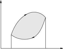
How can this be achieved? The answer is to compress the gas at lower pressures than during expansion. In other words, on the pV-diagram, the compression process must go below the expansion process, that is, the cycle must go clockwise (Figure 2.32).
Figure: 2.32. Heat engine cycle
For example, in the cycle in the figure, the work of the gas during expansion is equal to the area of \u200b\u200bthe curved trapezoid V1 1a2V2. Similarly, the work of the gas in compression is equal to the area of \u200b\u200bthe curved trapezoid V1 1b2V2 with a minus sign. As a result, the work A of the gas per cycle turns out to be positive and equal to the area of \u200b\u200bthe cycle 1a2b1.
Okay, but how to get the gas to return to its original state along a lower curve, that is, through states with lower pressures? Recall that for a given volume, the lower the temperature, the lower the gas pressure. Consequently, when compressed, the gas must pass through states with lower temperatures.
This is exactly what a refrigerator is for: to cool the gas during compression. The refrigerator can be the atmosphere (for internal combustion engines) or cooling running water (for steam turbines).
When cooled, the gas gives off a certain amount of heat Q2 to the refrigerator. The total amount of heat received by the gas per cycle is equal to Q1 Q2. According to the first law of thermodynamics:
Q1 Q2 \u003d A + U;
where U is the change in the internal energy of the gas per cycle. It is equal to zero: U \u003d 0, since the gas returned to its original state (and the internal energy, as we remember, is a function of the state). As a result, the gas work per cycle is equal to:
A \u003d Q1 Q2: |
As you can see, A< Q1 : не удаётся полностью превратить в работу поступающее от нагревателя тепло. Часть теплоты приходится отдавать холодильнику для обеспечения цикличности процесса.

cars
Fridge
Figure: 2.33. Refrigeration machine
Heater
Refrigerating body
An indicator of the efficiency of converting the energy of the burning fuel into mechanical work is the efficiency of the heat engine.
The efficiency of a heat engine is the ratio of mechanical work A to the amount of heat
you Q1 received from the heater:
A: Q1
Taking into account relation (2.12), we also have
Q 1Q 2 | |||
The efficiency of a heat engine, as we can see, is always less than unity. For example, the efficiency of steam turbines is about 25%, and the efficiency of internal combustion engines is about 40%.
2.12.2 Refrigeration machines
Everyday experience and physical experiments tell us that in the process of heat exchange, heat is transferred from a more heated body to a less heated one, but not vice versa. Processes have never been observed in which, due to heat exchange, energy spontaneously passes from a cold body to a hot one, as a result of which the cold body would cool down even more, and the hot body would heat up even more.
The key word here is "spontaneous". If you use an external source of energy, then it is quite possible to carry out the process of transferring heat from a cold body to a hot one. This is what refrigeration machines do.
Compared to a heat engine, the processes in the refrigerating machine have the opposite direction (Fig. 2.33).
The working body of the refrigeration machine is also called
which absorbs heat during expansion and gives off during compression21.
The refrigerator in a refrigerator is a body from which heat is removed. The refrigerator transfers the working
to the body (gas), the amount of heat Q2, as a result of which the gas expands.
During compression, the gas gives off heat Q1 to a more heated body, the heater. For such a heat transfer to take place, the gas must be compressed at higher temperatures than it was during expansion. This is possible only due to the work A0 performed by an external source (for example, an electric motor) 22. Therefore, the amount of heat
you transferred to the heater turns out to be more than the amount of heat taken from the cold
for the value of A0:
Q1 \u003d Q2 + A0:
21 In real refrigeration units The refrigerant is a volatile solution with a low boiling point, which takes heat during evaporation and gives it back during condensation.
22 In real refrigeration units, the electric motor creates a low pressure in the evaporator, as a result of which the refrigerant boils and takes heat; on the contrary, in the capacitor, the electric motor creates high pressure, under which the refrigerant condenses and gives off heat.

Thus, on the pV-diagram, the operating cycle of the refrigerating machine goes counterclockwise. The area of \u200b\u200bthe cycle is the work A0 performed by an external source (Figure 2.34).
Figure: 2.34. Chiller cycle
The main purpose of a refrigeration machine is to cool a tank (for example, a freezer). In this case, this reservoir plays the role of a refrigerator, and the environment serves as a heater, and the heat removed from the reservoir is dissipated into it.
An indicator of the efficiency of a refrigeration machine is a refrigerating coefficient equal to the ratio of heat removed from the refrigerator to the operation of an external source:
Q A 2 0:
The coefficient of performance can be more than one. In real refrigerators, it takes values \u200b\u200bfrom approximately 1 to 3.
There is another interesting application: a chiller can act as a heat pump. Then its purpose is to heat a certain reservoir (for example, heating a room) due to the heat removed from the environment. In this case, this tank will be the heater, and the environment will be the refrigerator.
The indicator of the efficiency of the heat pump is the heating coefficient equal to the ratio of the amount of heat transferred to the heated tank to the work
external source:
Q A 1 0:
The heating coefficient values \u200b\u200bof real heat pumps are usually in the range from 3 to 5.
2.12.3 Heat machine Karnot
The most important characteristics of a heat engine are the highest and lowest values \u200b\u200bof the temperature of the working fluid during the cycle. These values \u200b\u200bare referred to respectively as heater temperature and refrigerator temperature.
We have seen that the efficiency of a heat engine is strictly less than unity. A natural question arises: what is the highest possible efficiency of a heat engine with fixed values \u200b\u200bof the heater temperature T1 and the temperature of the refrigerator T2?
Let, for example, the maximum temperature of the engine working fluid is 1000 K, and the minimum temperature is 300 K. What is the theoretical limit of the efficiency of such a motor?
The answer to this question was given by the French physicist and engineer Sadi Carnot in 1824. He invented and researched a wonderful heat engine with ideal gas as
working fluid. This machine operates according to the Carnot cycle, which consists of two isotherms and two adiabats.
Consider a clockwise direct cycle of a Carnot machine (Fig. 2.35). In this case, the machine functions as a heat engine.
T 23
Figure: 2.35. Carnot cycle
Isotherm 1! 2. On site 1! 2, the gas is brought into thermal contact with a temperature heater T1 and expands isothermally. The amount of heat Q1 is supplied from the heater and is completely converted into work in this section: A12 \u003d Q1.
Adiabat 2! 3. For the purpose of subsequent compression, it is necessary to transfer the gas to a zone of lower temperatures. To do this, the gas is thermally insulated and then expands adiabatically at section 2! 3. During expansion, the gas performs positive work A23, and due to this, its internal energy decreases: U23 \u003d A23.
Isotherm 3! 4. The thermal insulation is removed, the gas is brought into thermal contact with the refrigerator at temperature T2. Isothermal compression occurs. The gas gives the refrigerator the amount of heat Q2 and performs negative work A34 \u003d Q2.
Adiabat 4! 1. This section is necessary to return the gas to its original state. During adiabatic compression, the gas performs negative work A41, and the change in internal energy is positive: U41 \u003d A41. The gas is heated to the initial temperature T1.
Karnot found the efficiency of this cycle (calculations, unfortunately, are outside the scope of the school curriculum):
T 1T 2 | |||
In addition, he proved that the efficiency of the Carnot cycle is the highest possible for all heat engines with a heater temperature T1 and a refrigerator temperature T2.
So, in the above example (T1 \u003d 1000 K, T2 \u003d 300 K) we have:
max \u003d 1000 300 \u003d 0; 7 (\u003d 70%): 1000
What is the point of using isotherms and adiabats, and not some other processes? It turns out that isothermal and adiabatic processes make the Carnot machine reversible. It can be started in a reverse cycle (counterclockwise) between the same heater and refrigerator, without involving other devices. In this case, the Carnot machine will function as a chiller.
The ability to run a Carnot machine in both directions plays a very important role in thermodynamics. For example, this fact serves as a link in the proof of the maximal efficiency of the Carnot cycle. We will return to this in the next article devoted to the second law of thermodynamics.
1.Heating machines.
- a device that converts heat into mechanical work (heat engine) or mechanical work into heat (refrigerator). The transformation is carried out by changing the internal energy of the working fluid - in practice, usually liquid or gas.
In short, heat engines transform warmth into work or, conversely, work into warmth.
Examples of heat engines: Internal combustion engine (ICE) a) carburetor engine b) diesel engine in) jet engine Steam and gas turbines.
1.1. The history of the creation of heat engines.
Many believe that the history of steam engines began only in the late 17th century in England. But this is not entirely true.
Back in the first century BC, one of the great scientists of ancient Greece, Heron of Alexandria, wrote the treatise "Pneumatics". It described machines that used heat energy. The most interesting for us were two heat engines.
Eolipil - a ball "Eola", rotated around its axis under the action of steam coming out of it. In fact it wasthe prototype of future steam turbines.
Another remarkable device of the Heron of Alexandria was the drive of the doors of the temple, which opened under the influence of the fire lit on the altar. When detailed analysis in this complex system of mechanisms we can seefirst steam pump.
All heat engines created by Hero of Alexandria were used only as toys. They were not in demand at the time.
The real history of steam engines begins only in the 17th century. One of the first to createcurrent prototype of the steam engine, was Denis Papin. Papen's steam engine was actually just a sketch, a model. He never managed to create a real steam engine that could be used in production. 1680 - Invented the steam boiler in 1681. - Equipped it with a 1690 safety valve. - He was the first to use steam to lift the piston and describe the closed thermodynamic cycle of a steam engine. 1707 - Provided a description of his engine. But his works were not forgotten for millennia as the works of Heron. All his ideas were applied in the next generation of steam engines.
If it is very difficult to establish exactly who was the first in the history of technology to create a steam engine, then it is known for certain who was the first to patent and apply in practice his steam engine. In 1698, the Englishman Thomas Severi registered the firstpatent for a device "for raising water and for obtaining movement of all types of production using the driving force of fire ..."... As you can see, the description of the patent is very vague. In fact, he created the first steam pump. The only thing he could do was raise the water. At the same time, the pump efficiency was extremely low, and the consumption of coal was simply enormous. Therefore, the pump was mainly used in coal mines. They were pumped out groundwater.
In 1712, the world sawsteam machine Thomas Newcomen. Newcomen's steam engine absorbed best ideas from the Papen steam engine and the Severi steam pump. In it, a steam cylinder with a piston was used to perform movement, as in the Papen steam engine. In this case, steam was obtained separately, in a steam boiler, as in the Severi steam pump.
Despite a major breakthrough in the creation of steam engines, the Newcomen machine received its main distribution only as a drive for water pumps. The main disadvantages of Newcomen's steam engine were its enormous size and high consumption of coal. Attempts to use it to drive steamers were unsuccessful.
Over 50 years steam machine Newcomen remained unchanged. In 1763, James Watt, a mechanic at the University of Glasgow, was offered to fix Newcomen's steam engine. In the process of working with Newcomen's machine, Watt comes to the idea that it would be nice to improve it.
First, Watt decides to keep the steam cylinder hot at all times. This will reduce the consumption of coal. To do this, he creates a condenser to cool the steam. The next thing it does is change the way the steam cylinder works. If in the Newcomen steam engine the machine performed its working stroke under the influence of atmospheric pressure, then in the Watt steam engine, the piston performed its working stroke under the action of steam pressure. This made it possible to increase the cylinder pressure and reduce the size of the steam engine.
In 1773, Watt builds his firstoperating steam engine... And in 1774, together with the industrialist Matthew Bolton, Watt opened a company for the production of steam engines. From 1775 to 1785 - 56 steam engines were built by the Watt firm. From 1785 to 1795 - 144 of these machines have already been delivered by the same company. Things were going well and Bolton asked Watt to create a steam engine for his new sheet rolling mill.
In 1884, Watt creates the firstuniversal steam machine. Its main purpose is to drive industrial machine tools. From this point on, the steam engine is no longer tied to coal mines. They begin to use it in factories, install it on steamers, and create trains.
It was Watt's steam engine that made a technological breakthrough in technology. She opened a new era in the history of technology - the era of steam engines.
First steam car 1770g... Jean Cugno - French engineer, built the first self-propelled cart, designed to move artillery pieces
"Younger brother" - steam locomotive 1803 - English inventor Richard Trevithick constructed the first steam locomotive. After 5 years, Trevithick built a new steam locomotive. he developed a speed of up to 30 km / h. In 1816, without support, Trevithick went bankrupt and left for South America
The decisive role of 1781-1848. - English designer and inventor George Stephenson 1814. - He started building steam locomotives. 1823 He founded the world's first steam locomotive plant in 1829. In the competition for the best locomotives, Stephenson's Raketa steam locomotive took first place. Its power was 13 hp and the speed was 47 km / h.
Internal combustion engine 1860 - The French mechanic Lenoir invented the internal combustion engine in 1878. - The German inventor Otto designed a four-stroke internal combustion engine. 1825 - German inventor Daimler created a gasoline internal combustion engine around the same time Gas engine was developed by Kostovich in Russia.
Special device. Carburetor. German engineer Rudolf Diesel designed an internal combustion engine in which not a combustible mixture was compressed, but air. These are the most economical heat engines 1) operate on cheap types of fuel 2) have an efficiency of 31-44% on September 29, 1913. Boarded a steamer to London. The next morning they did not find him in the cabin. It is believed that he committed suicide by throwing himself into the waters of the English Channel at night.
1.2. The principle of operation of the heat engine.
Heat engines can be arranged in various ways, but in any heat engine there must be a working substance or a body that performs mechanical work in the working part of the machine, a heater, where the working substance receives energy, and a refrigerator that removes heat from the working body.
The working medium can be steam or gas.
1.3. Types of heat engines.
There are two types of heat engines - depending on the direction of the processes taking place in them:
1.
Heat engines convert heat from an external source into mechanical work.
Refrigeration machinestransfer heat from a less heated body to a more heated one due to the mechanical work of an external source.
Let's consider these types of heat engines in more detail.
1.3.1. Heat engines.
We know that doing work on a body is one of the ways to change its internal energy: the perfect work, as it were, dissolves in the body, turning into the energy of the chaotic movement and interaction of its particles.
A heat engine is a device that, on the contrary, extracts useful work from the "chaotic" internal energy of the body. The invention of the heat engine really changed the face of human civilization.
A schematic diagram of a heat engine can be depicted as follows:
Let's see what the elements of this diagram mean.
Working body the engine is gas. It expands, moves the piston and thus performs useful mechanical work.
But in order to force the gas to expand, overcoming external forces, it is necessary to heat it to a temperature that is significantly higher than the ambient temperature. For this, the gas is brought into contact with a heater - burning fuel.
In the process of fuel combustion, significant energy is released, part of which is used to heat the gas. Gas receives the amount of heat Qн from the heater ... It is because of this heat that the engine does useful work.A .
This is all clear, but what is a refrigerator and why is it needed?
With a single gas expansion, we can use the incoming heat as efficiently as possible and turn it entirely into work. For this, it is necessary to expand the gas isothermally: the first law of thermodynamics, as we know, gives us in this case A \u003d Qn.
But no one needs a one-time expansion. The engine must run cyclically, providing periodic repeatability of piston movements. Therefore, at the end of the expansion, the gas must be compressed, returning it to its original state.
In the process of expansion, the gas does some useful work A1. In the process of compression, positive work A2 is performed on the gas (and the gas itself does negative work A2). As a result, the useful work of the gas for the cycle is A \u003d A1-A2.
Of course, there must be A\u003e 0 or A2<А1 (иначе никакого смысла в двигателе нет). Сжимая газ, мы должны совершить меньшую работу, чем совершил газ при расширении.
How can this be achieved? Answer: Compress gas under lower pressures than during expansion. In other words, on the pV-diagram, the compression process must go below the expansion process, i.e., the cycle should be traversed clockwise.
For example, in the cycle in the figure, the work of the gas during expansion is equal to the area of \u200b\u200bthe curved trapezoid V11a2V2. Similarly, the gas compression work is equal to the area of \u200b\u200bthe curved trapezoid V11b2V2 with a minus sign. As a result, the work A of the gas per cycle turns out to be positive and equal to the area of \u200b\u200bthe cycle 1a2b1.
Ok, but how do you get the gas to return to its original state along a lower curve, i.e. e. Through states with smaller divisions? Recall that for a given volume, the lower the temperature, the lower the gas pressure. Therefore, when compressed, the gas must pass through states with lower temperatures.
This is exactly what a refrigerator is for: tocool gas in the process of compression. The refrigerator can be the atmosphere (for internal combustion engines) or cooling running water (for steam turbines).
When cooled, the gas gives off a certain amount of heat Q2 to the refrigerator. The total amount of heat received by the gas per cycle becomes equal to Q1-Q2. According to the first law of thermodynamics:
Q 1- Q 2 \u003d A + deltaU,
where deltaU is the change in the internal gas energy per cycle It is equal to zero deltaU \u003d 0, since the gas returned to its original state (and the internal energy, as we remember, is state function). As a result, the gas work per cycle is equal to:
A \u003d Q 1- Q 2.
As you can see, A An indicator of the efficiency of converting the energy of the burning fuel into mechanical work is the efficiency of the heat engine. Heat engine efficiency Is the ratio of mechanical work A to the amount of heat Q1 supplied from the heater. The efficiency of a heat engine, as we can see, is always less than unity. For example, the efficiency of steam turbines is about 25%, and the efficiency of the internal combustion engine is about 40%. 1.3.2. Refrigerating machines. Everyday experience and physical experiments tell us that in the process of heat exchange, heat is transferred from a more heated body to a less heated one, but not vice versa. Processes are never observed in which, due to heat exchange, energy spontaneously passes from a cold body to a hot one, as a result of which the cold body would cool down even more, and the hot body - even more heated. The key word here is "spontaneous". If you use an external source of energy, then it is quite possible to carry out the process of transferring heat from a cold body to a hot one. This is what refrigeration machines do. Working body refrigeration machine is also calledrefrigerant (in real refrigeration plants, the refrigerant is a volatile solution with a low boiling point, which takes heat during evaporation and gives it back during condensation). For the sake of simplicity, we will consider it a gas that absorbs heat during expansion and gives off during compression. Fridge (T2) in a refrigerating machine is a body from which heat is removed. The refrigerator transfers the amount of heat Q2 to the working fluid (gas), as a result of which the gas expands. During compression, the gas gives off heat Q1 to a more heated body - a heater (T1). For such a heat transfer to take place, the gas must be compressed at higher temperatures than it was during expansion. This is possible only due to the work A performed by an external source (for example, an electric motor) (in real refrigeration plants, the electric motor creates a low pressure in the evaporator, as a result of which the refrigerant boils and takes heat; on the contrary, the electric motor creates a high pressure in the condenser, under which the refrigerant condenses and gives off warmth). Therefore, the amount of heat transferred to the heater turns out to be greater than the amount of heat taken from the refrigerator, just by the value A. Q 1 \u003d Q 2 + A. Thus, on the pV-diagram, the operating cycle of the refrigeration machine goes counterclock-wise... The area of \u200b\u200bthe cycle is the work A performed by an external source, The indicator of the efficiency of the refrigeration machine is refrigeration coefficientequal to the ratio of heat removed from the refrigerator to the work of an external source: A \u003d Q 2 / A The refrigerating coefficient can be more than one. In real refrigerators, it takes values \u200b\u200bfrom approximately 1 to 3. There is another interesting application: a chiller can act as a heat pump. Then its purpose is to heat a certain reservoir (for example, to heat a room) due to the heat removed from the environment. In this case, this reservoir will be the heater and the environment will be the refrigerator. An indicator of the efficiency of the heat pump is heating coefficientequal to the ratio of the amount of heat transferred to the heated tank to the work of an external source. The heating coefficient values \u200b\u200bof real heat pumps are usually in the range from 3 to 5. 1.4. Heat engine Karnot. The most important characteristics of a heat engine are the highest and lowest values \u200b\u200bof the temperature of the working fluid during the cycle. These values \u200b\u200bare named accordinglyheater temperature and temperature of the refrigerator. We have seen that the efficiency of a heat engine is strictly less than unity. A natural question arises: what is the highest possible efficiency of a heat engine with fixed values \u200b\u200bof the heater temperature T1 and the temperature of the refrigerator T2? Let, for example, the maximum body temperature of a working engine is 1000 K, and the minimum is 300 K. What is the theoretical limit of the efficiency of such a motor? The answer to this question was given by the French physicist and engineer Sadi Carnot in 1824. He invented and researched a wonderful heat engine with an ideal gas as a working fluid. This machine works according to the Carnot cycle consisting of two isotherms and two adiabats. Consider a forward loop Carnot machine going clockwise. In this case, the machine functions as a heat engine. Isotherm 1-2. In section 1-2, the gas is brought into thermal contact with the temperature heater T1 and expands isothermally. The amount of heat Q1 is supplied from the heater and is completely converted into work in this section: A12 \u003d Q1. Adiabat 2-3. For the next compression, it is necessary to transfer the gas to a lower temperature zone. For this, the gas is thermally insulated, and then expands adiabatically in section 2-3. When expanding, the gas does positive work A23, and due to this, its internal energy decreases: deltaU23 \u003d - A23. Isotherm 3-4. The thermal insulation is removed, the gas is brought into thermal contact with the refrigerator at temperature T2. Isothermal compression occurs. The gas gives the amount of heat Q2 to the refrigerator and does negative work A34 \u003d - Q2. Adiabat 4-1. This section is necessary to return the gas to its original state. In the course of adiabatic compression, the gas performs negative work A41. The gas is heated to the initial temperature T1. Karnot found the efficiency of this cycle (calculations, unfortunately, are outside the scope of the school curriculum). Moreover, he proved thatThe efficiency of the Carnot cycle is the maximum possible for all heat engines with a heater temperature T1 and a refrigerator temperature T2... So, in the above example (T1 \u003d 1000 K, T2 \u003d 300 K) we have: Efficiencymax \u003d (1000-300): 1000 \u003d 0.7 (\u003d 70%) What is the point of using isotherms and adiabats, and not some other processes? It turns out that isothermal and adiabatic processes make the Carnot machine reversible ... It can be run byreverse loop (counterclockwise) between the same heater and refrigerator without involving other devices. In this case, the Carnot machine will function as a chiller. The ability to run a Carnot machine in both directions plays a very important role in thermodynamics. For example, this fact serves as a link in the proof of the maximum efficiency of the Carnot cycle. 2. Rocket. - (from Italian rocchetta - a small spindle through it. Rakete or Dutch. raket) - an aircraft moving in space due to the action of jet thrust, arising only as a result of the rejection of a part of its own mass (working body) of the device and without the use of matter from the environment ... Since the flight of a rocket does not necessarily require the presence of an ambient air or gas environment, it is possible not only in the atmosphere, but also in a vacuum. The word "rocket" denotes a wide range of flying devices from a festive firecracker to a space launch vehicle. In military terminology, the word rocket denotes a class, as a rule, of unmanned aerial vehicles used to engage remote targets and using the principle of jet propulsion for flight. In connection with the diverse use of missiles in the armed forces, various branches of the military, a wide class of different types of missile weapons has been formed. 1.1. History of rocket science. There is an assumption that some semblance of a rocket was designed back in Ancient Greece by Alix Sin. We are talking about a flying wooden pigeon of Archit of Tarentum.His invention is mentioned in the work the ancient Roman writer Aulus Gellius "Attic nights". The book says that the bird was lifted with weights and set in motion by a breath of hidden and hidden air. It has not yet been established: was the pigeon set in motion by the air inside it or the air that blew on it from the outside? It remains unclear how Archytas could have gotten the compressed air inside the pigeon. In the ancient tradition pneumatics there are no analogues of such use of compressed air. Most historians attribute the origins of rockets to the times Chinese Han Dynasty (206 BC - 220 AD), to the discovery of gunpowder and the beginning of its use for fireworks and entertainment. The force generated by the explosion of the powder charge was sufficient to move various objects.Later, this principle was applied when creating the first guns and muskets. Powder weapon shellscould fly over long distances, but were not missiles, since they did not have their own supplies fuel. Nevertheless, it was the invention of gunpowder that became the main prerequisite for the emergence of real missiles. The first rocket was created by man at least 700 years ago. In the 13th century, the Chinese first used rockets or, as they were then called, "fire arrows" against the Mongol invaders and plunged the enemy into confusion and panic. In the Battle of Kaiken in 1232, the Chinese unleashed "fiery arrows", a tube made of compacted paper was attached to them, open only at the rear end and filled with a combustible compound. This charge was ignited, and then the arrow was fired using a bow. Such arrows were used in a number of cases during the siege of fortifications, against ships, cavalry. After the Battle of Kaiken, the Mongols began producing their own missiles and spreading the first missile technology in Europe. From the 13th to the 15th centuries, there were reports of various experiments with rockets. In England, a monk named Roger Bacon was working on a new powder formula that would increase the range of rocket projectiles. In France, Jean Froissart discovered that the projectile's flight could be more accurate if the rocket was fired through a tube. After several centuries, Froissard's idea gave impetus to the creation of anti-tank missile shells like a bazooka. In Italy, Gian de Fontana developed a torpedo-like missile that moved on the surface of the water to set fire to enemy ships. However, the Indian prince Haydar Ali, who ruled in the kingdom of Mysore (or Karnataka), in the south of India, can be called an innovator of rocket technology in their modern day. During the wars between Mysore and the British East Indian Trading Company Haydar, Ali used rockets and rocket regiments in the form of regular troops. The main technological innovation was the use of a high-quality metal shell, in which a charge of gunpowder was placed (this is how the first combustion chamber appeared). Haydar Ali also created special trained missile squads that could direct missiles to distant targets with acceptable accuracy. The use of missiles in the Anglo-Mysore wars led the British to the idea of \u200b\u200busing this type of weapon. William Congreve, an officer in the British forces that captured several Indian rockets as a trophy, sent these shells to England for further study and development. In 1804 Congreve, the son of the chief of the royal arsenal at Woolwich, near London, began developing a rocket program and mass-producing rockets. Congreve made a new fuel mixture and developed a rocket engine and a metal tube with a tapered tip. These rockets, which weighed 15 kg, were called Congreve Rockets. Rocket artillery was widely used until the end of the 19th century. The rockets were lighter and more mobile than artillery pieces. The accuracy and accuracy of firing missiles was small, but comparable to the artillery of that time. However, in the second half of the 19th century, rifled artillery guns appeared, providing greater accuracy and accuracy of fire, and rocket artillery was removed from service everywhere. Only fireworks and signal flares. At the end of the 19th century, attempts were made to mathematically explain jet propulsion and create more effective missile weapons. In Russia, Nikolai Tikhomirov was one of the first to deal with this issue in 1894. Konstantin Tsiolkovsky studied the theory of jet propulsion. He put forward the idea of \u200b\u200busing rockets for space flight and argued that the most efficient fuel for them would be a combination of liquid oxygen and hydrogen. He designed a rocket for interplanetary communications in 1903. German scientist Hermann Obert in the 1920s also laid out the principles of interplanetary flight. In addition, he conducted bench tests of rocket engines. American scientist Robert Goddart began developing a liquid propellant rocket engine in 1923, and a working prototype was built by the end of 1925. March 16, 1926 he launched the first liquid-propellant rocket using gasoline and liquid oxygen as fuel. On August 17, 1933, the GIRD 9 rocket was launched, which can be considered the first Soviet anti-aircraft missile. She reached an altitude of 1.5 km. And the next rocket "GIRD 10", launched on November 25, 1933, has already reached an altitude of 5 km. On March 14, 1931, VfR member Johannes Winkler carried out the first successful launch of a liquid propellant rocket in Europe. In 1957. in the USSR, under the leadership of Sergei Korolev, the world's first intercontinental ballistic missile R-7 was created as a means of delivering nuclear weapons, which in the same year was used to launch the world's first artificial Earth satellite. So the use of rockets for space flights began. 2.2. Forces acting on a rocket in flight. The science of studying the forces acting on rockets or other spacecraft is called astrodynamics. The main forces acting on a rocket in flight: Engine thrust. When moving in the atmosphere - any resistance. Lift force. Usually small, but significant for rocket gliders. 2.3. The use of missiles. 2.3.1. Military. Missiles are used as a method of delivering weapons to the target.
The small size and high speed of movement of missiles provides them with low vulnerability. Since a pilot is not needed to control a combat missile, it can carry charges of great destructive power, including nuclear ones. Modern homing and navigation systems give rockets greater accuracy and maneuverability. There are many types of combat missiles differing in flight range, as well as in the place of launch and the place of hitting the target ("ground" - "air"). Antimissile defense systems are used to combat combat missiles. There are also flares and flares. 2.3.2. Scientific research. Geophysical and meteorological rockets are used instead of airplanes and balloons at an altitude of more than 30-40 kilometers. The rockets do not have a limiting ceiling and are used to sound the upper atmosphere, mainly the mesosphere and ionosphere. There is a division of rockets into light meteorological rockets, capable of raising one set of instruments to an altitude of about 100 kilometers, and heavy geophysical rockets, which can carry several sets of instruments and whose flight altitude is practically unlimited. Typically, scientific rockets are equipped with instruments for measuring atmospheric pressure, magnetic field, cosmic radiation and air composition, as well as equipment for transmitting the measurement results by radio to the earth. There are models of rockets, where instruments with data obtained during the ascent are lowered to the ground using parachutes. Rocket meteorological research preceded satellite research, so the first meteorological satellites had the same instruments as the meteorological rockets. The rocket was first launched to study air parameters on April 11, 1937, but regular rocket launches began in the 1950s, when a series of specialized scientific rockets were created. 2.3.3. Cosmonautics. The rocket is still the only vehicle capable of launching a spacecraft into space. Alternative ways to lift spacecraft into orbit, such as the "space elevator", electromagnetic and conventional guns, are still in the design stage. 2.3.4. Sport. There are people who are into rocketry sports whose hobby is building and launching rocket models. Also, rockets are used in amateur and professional fireworks. 3. Jet engine. An engine that creates the thrust force necessary for movement by converting the internal energy of the fuel into the kinetic energy of the jet stream of the working fluid A working fluid, as applied to engines, is understood as a substance (gas, liquid, solid), with the help of which the thermal energy released during the combustion of fuel is converted into useful mechanical work. Various types of energy (chemical, nuclear, electric, solar) can be converted into kinetic (high-speed) energy of a jet stream in a rocket engine. The basis of a jet engine is a combustion chamber, where fuel (a source of primary energy) is burned and a working fluid is generated - hot gases (products of fuel combustion). The main feature of the reactive force is that it arises as a result of the interaction of parts of the system without any interaction with external bodies. 3.1. History of jet engines. The history of jet engines is inextricably linked with the history of aviation. Progress in aviation throughout its entire existence was ensured mainly by the progress of aircraft engines, and all the increasing requirements imposed by aviation on engines were a powerful stimulator of the development of aircraft engine building. The Flyer-1, considered the first aircraft, was equipped with a piston internal combustion engine, and this technical solution remained indispensable in aviation for forty years. Aircraft piston engines were improved, their power and thrust-to-weight ratio of the aircraft themselves increased. At the very beginning of the 30s, work was launched in the USSR related to the creation of a jet engine for aircraft. Back in 1920, the Soviet engineer F.A. Tsander put forward the idea of \u200b\u200ba high-altitude rocket plane. Its OR-2 engine, which ran on gasoline and liquid oxygen, was intended for installation on a prototype aircraft. In 1939, in the USSR, flight tests of ramjet engines (ramjet) on the I-15 aircraft designed by NN Polikarpov took place. The ramjet engine designed by I.A. Merkulov was installed on the lower planes of the aircraft as additional motors. The first flights were conducted by an experienced test pilot P.E. Loginov. At a given altitude, he accelerated the car to maximum speed and turned on the jet engines. The thrust of additional ramjet engines increased the maximum flight speed. In 1939, reliable starting of the engine in flight and the stability of the combustion process were worked out. In flight, the pilot could repeatedly turn on and off the engine and adjust its thrust. On January 25, 1940, after factory testing of the engines and checking their safety, an official test took place on many flights - a flight of an aircraft with a ramjet engine. Starting from the Frunze Central Aerodrome in Moscow, the pilot Loginov turned on his jet engines at a low altitude and made several circles over the airfield area. In the summer of 1940 these engines were installed and tested on the I-153 "Chaika" fighter designed by NN Polikarpov. They increased the speed of the aircraft by 40-50 km / h. However, at flight speeds that could be developed by propeller driven aircraft, additional compressorless air-jet engines consumed a lot of fuel. The ramjet has another important drawback: such an engine does not provide thrust in place and, therefore, cannot provide an independent takeoff of the aircraft. This means that an aircraft with a similar engine must be necessarily equipped with some kind of auxiliary launch power plant, for example, a propeller-driven one, otherwise it will not take off. Work on the creation of combat jet aircraft was widely carried out abroad. In June 1942, the first flight of the German jet fighter-interceptor "Me-163" designed by Messerschmitt took place. Only the ninth version of this aircraft was put into mass production in 1944. For the first time, this aircraft with a liquid-propellant engine was used in a combat situation in mid-1944 during the invasion of France by allied forces. It was intended to fight enemy bombers and fighters over German territory. The aircraft was a monoplane without a horizontal tail, which was made possible due to the large sweep of the wing. In Italy, in August 1940, the first 10-minute flight of the Campini-Caproni SS-2 monoplane jet was made. On this aircraft, the so-called motor-compressor VRM was installed (this type of VRM was not considered in the review of jet engines, since it turned out to be unprofitable and did not receive distribution). In May 1941, the first test flight of the Gloucester "E-28/39" experimental aircraft with a turbojet engine with a Whittle design centrifugal compressor took place in England. At 17 thousand revolutions per minute, this engine developed a thrust of about 3800 Newtons. The experimental aircraft was a single-seat fighter with one turbojet engine located in the fuselage behind the cockpit. The aircraft had a tricycle landing gear retractable in flight. A year and a half later, in October 1942, the first flight test of the American jet fighter "Ercomet" R-59A with two turbojet engines designed by Whittle was carried out. It was a mid-wing monoplane with a high tail unit. During flight tests, a speed of 800 kilometers per hour was reached. Among other aircraft with turbojet engines of this period, the Gloucester Meteor fighter should be noted, the first flight of which took place in 1943. This single-seat, all-metal monoplane proved to be one of the most successful jet fighters of the period. Two turbojet engines were installed on a low-lying cantilever wing. The serial combat aircraft developed a speed of 810 kilometers per hour. The flight duration was about 1.5 hours, the ceiling was 12 kilometers. The aircraft had 4 automatic cannons of 20 mm caliber. The car had good maneuverability and controllability at all speeds. In November 1941, a world speed record of 975 kilometers per hour was set on a special record version of this machine. Already in the initial period of the development of jet engines, the former familiar forms of aircraft underwent more or less significant changes. For example, the British jet fighter "Vampire" of a two-boom design looked very unusual. In our country, during the Great Patriotic War, extensive research work began on the creation of combat aircraft with turbojet engines. The war set the task - to create a fighter aircraft with not only high speed, but also a significant flight duration: after all, the developed jet fighters with liquid propellant engines had a very short flight duration - only 8-15 minutes. Combat aircraft were developed with a combined propulsion system - propeller driven and jet. For example, the La-7 and La-9 fighters were equipped with jet boosters. Work on one of the first Soviet jet aircraft began back in 1943-1944. This combat vehicle was created by a design team headed by General of the Aviation Engineering Service Artem Ivanovich Mikoyan. It was the I-250 fighter with a combined power plant, which consisted of a liquid-cooled piston aircraft engine of the VK-107 A type with a propeller and a WFD, the compressor of which was rotated by a piston engine. The I-250 made its first flight back in March 1945. During flight tests, a speed of well over 800 kilometers per hour was achieved. Soon the same team of designers created the MIG-9 jet fighter. It was equipped with two turbojet engines of the "RD-20" type. On April 24, 1946, test pilot A.N. Grinchik made the first flight on the MIG-9 aircraft. Like the BI aircraft, this aircraft differed little in its design from piston aircraft. The maximum speed of the MIG-9 exceeded 900 kilometers per hour. At the end of 1946, this machine was put into mass production. In April 1946, the first flight was made on a jet fighter designed by A.S. Yakovlev. The persistent creative work of research, design and production teams was crowned with success: the new domestic jet aircraft were in no way inferior to the world aviation technology of that period. Among the high-speed jet aircraft created in the USSR in 1946-1947, the jet fighter designed by AI Mikoyan and MI Gurevich “MIG-15”, with a swept wing and tail, stands out for its high tactical flight and operational characteristics. The use of a swept wing and empennage increased the horizontal flight speed without significant changes in its stability and controllability. An increase in the aircraft's speed was also largely facilitated by an increase in its power-to-weight ratio: a new turbojet engine with an RD-45 centrifugal compressor with a thrust of about 19.5 kilonewtons at 12 thousand rpm was installed on it. The horizontal and vertical speeds of this machine surpassed everything previously achieved on jet aircraft. The design bureau, working under the leadership of S.A. Lavochkin, simultaneously with the release of the "MIG-15" created a new jet fighter "La-15". It had a swept wing located above the fuselage. It had powerful onboard weapons. Of all the swept-wing fighters that existed at that time, the La-15 had the least flight weight. Thanks to this, the La-15 aircraft with the RD-500 engine, which had less thrust than the RD-45 engine installed on the MIG-15, had approximately the same flight and tactical data as the MIG- 15". The sweep and special profile of the wings and tail of jet aircraft dramatically reduced air resistance when flying at the speed of sound propagation. Now, during the wave crisis, the resistance increased not 8-12 times, but only 2-3 times. This was confirmed by the first supersonic flights of Soviet jet aircraft. 3.2. Application of jet technology in civil aviation. Soon jet engines began to be installed on civil aircraft. In 1955, the multi-seat passenger jet “Kometa-1” began operating abroad. This passenger car with four turbojet engines had a speed of about 800 kilometers per hour at an altitude of 12 kilometers. The plane could carry 48 passengers. The flight range was about 4 thousand kilometers. However, after a major accident of this aircraft in the Mediterranean, its operation was discontinued. Soon the constructive version of this aircraft - "Comet-3" was used. In 1959, the operation of the French passenger aircraft "Caravel" began. The aircraft had a round fuselage with a diameter of 3.2 meters, which was equipped with a pressurized compartment 25.4 meters long. The power plant consisted of two turbojet engines with a thrust of 40 kilonewtons each. The plane's speed was about 800 kilometers per hour. In the USSR, already in 1954, on one of the air routes, the delivery of urgent cargo and mail was carried out by high-speed jet aircraft "Il-20".This aircraft with two turbojet engines of 80 kilonewtons each had excellent aerodynamic shapes. "TU-104" was highly appreciated both in our country and abroad. Foreign experts, speaking in print, stated that having started regular passenger transportation on jet aircraft “TU-104”, the Soviet Union was two years ahead of the United States, England and other Western countries in the mass operation of passenger turbojet aircraft: the American jet aircraft “Boeing-707 ”And the English“ Comet-IV ”went on air lines only at the end of 1958, and the French“ Caravel ”- in 1959. TVD is an intermediate type of aircraft power plant. Although the gases exiting the turbine are discharged through the nozzle and their reaction generates some thrust, the main thrust is created by a working propeller, like in a conventional propeller-driven aircraft. The theater of operations did not become widespread in combat aviation, since it cannot provide such a speed of movement as purely jet engines. It is also unsuitable on express lines of civil aviation, where speed is a decisive factor, and questions of economy and cost of the flight fade into the background. However, it is advisable to use turboprop aircraft on routes of various lengths, flights on which are made at speeds of about 600-800 kilometers per hour. It should be borne in mind that, as experience has shown, the transportation of passengers by them over a distance of 1000 kilometers is 30% cheaper than on propeller driven aircraft with piston aircraft engines. 3.3. The principle of operation of jet engines. The jet engine is based on an ordinary rocket device. It works as follows. In a special chamber with one outlet with a conical tube - a nozzle, fuel is burned. The gaseous products of combustion fly out through the nozzle at an enormous speed. When fuel is burned, an increased pressure of up to 80-100 atmospheres is formed in the chamber. This pressure acts in all directions with equal force. The pressures on the side walls of the chamber are mutually balanced. The force acting on the front wall is not balanced by anything, since in the opposite side the gases are freely ejected through the hole. Therefore, the resultant of all the forces of pressure on the walls of the chamber makes the rocket engine move forward. To create the jet thrust used by the rocket engine, it is necessary to: a source of initial (primary) energy, which is converted into kinetic energy of the jet stream; a working fluid that is ejected from the reactor in the form of a jet stream; R. d. itself is an energy converter. The initial energy is stored on board an aircraft or other apparatus equipped with a radioactive fuel (chemical fuel, nuclear fuel), or (in principle) can come from outside (solar energy). To obtain a working fluid in R. d. Maybea substance taken from the environment (for example, air or water) is used; the substance that is in the tanks of the apparatus or directly in the chamber of R. d .; a mixture of substances coming from the environment and stored on board the vehicle. In modern energy production, chemical energy is most often used as primary energy. In this case, the working fluid is hot gases - products of combustion of chemical fuel. During the operation of a rocket engine, the chemical energy of combustible substances is converted into thermal energy of combustion products, and the thermal energy of hot gases is converted into mechanical energy of the translational motion of the jet stream and, consequently, of the apparatus on which the engine is installed. The main part of any combustion chamber is the combustion chamber in which the working fluid is generated. The end part of the chamber, which serves to accelerate the working fluid and obtain a jet stream, is called a jet nozzle. Everyone knows that after a shot, a gun or rifle is given back. This happens because a projectile or a bullet with a high speed flies out of the muzzle of a gun or rifle barrel. And the tool itself, due to the force of reaction, receives a movement in the opposite direction. The projectiles are pushed out by gases generated by the combustion of the powder. If we did not strengthen the gun barrel on the gun carriage, but let it move freely, then after the shot the barrel would fly back like a rocket. The flight of conventional aircraft is impossible in a space devoid of air. The lift force of an airplane is created only by the action of the air jet on its wings. An airship or balloon can only fly if it is lighter than air of the same volume. In this sense, rocket engines have a huge advantage over conventional aircraft. The rocket motor operates independently of the environment; it does not need air support. Spacecraft equipped with rocket engines can fly not only in highly rarefied air, but even in airless space. In recent years, a variety of more or less successful experiments have been done on the application of jet engines to various types of vehicles. Let's consider this process in relation to jet engines. Let's start with the combustion chamber of the engine, in which a combustible mixture has already been created in one way or another, depending on the type of engine and the type of fuel. It can be, for example, a mixture of air with kerosene, as in a turbojet engine of a modern jet aircraft, or a mixture of liquid oxygen with alcohol, as in some liquid-propellant rocket engines, or, finally, some solid fuel for powder rockets. The combustible mixture can burn, i.e. enter into a chemical reaction with a violent release of energy in the form of heat. The ability to release energy during a chemical reaction is the potential chemical energy of the mixture molecules. The chemical energy of molecules is associated with the peculiarities of their structure, more precisely, the structure of their electronic shells, i.e. of the electron cloud that surrounds the nuclei of the atoms that make up the molecule. As a result of a chemical reaction, in which some molecules are destroyed, while others arise, naturally, a rearrangement of the electron shells occurs. This restructuring is a source of released chemical energy. It can be seen that only substances that, during a chemical reaction in the engine (combustion), emit a lot of heat, and also form a large amount of gases, can serve as fuel for jet engines. All these processes take place in the combustion chamber, but let's dwell on the reactions not at the molecular level (this has already been discussed above), but at the "phases" of work. Until combustion has begun, the mixture has a large store of potential chemical energy. But then the flame engulfed the mixture, another moment - and the chemical reaction was over. Now, instead of molecules of the combustible mixture, the chamber is filled with molecules of combustion products, more densely "packed". The excess binding energy, which is the chemical energy of the past combustion reaction, is released. The molecules possessing this excess energy transferred it almost instantly to other molecules and atoms as a result of frequent collisions with them. All molecules and atoms in the combustion chamber began to move randomly, chaotically at a much higher speed, the temperature of the gases increased. This is how the potential chemical energy of the fuel was converted into thermal energy of combustion products. A similar transition was carried out in all other heat engines, but jet engines are fundamentally different from them with regard to the further fate of incandescent combustion products. After hot gases have formed in a heat engine, containing a large thermal energy, this energy must be converted into mechanical energy. After all, the engines are used to do mechanical work, to "move" something, to put it into action, it doesn't matter whether it is a dynamo machine when asked to add drawings to a power plant, a diesel locomotive, a car or an airplane. In order for the thermal energy of gases to pass into mechanical energy, their volume must increase. With this expansion, the gases do the work, which consumes their internal and thermal energy. In the case of a piston engine, the expanding gases press on the piston moving inside the cylinder, the piston pushes the connecting rod, which already rotates the engine crankshaft. The shaft is connected to the rotor of the dynamo, the driving axles of a diesel locomotive or car, or the propeller of an aircraft - the engine does useful work. In a steam engine, or a gas turbine, gases expanding, forcing the wheel connected to the turbine shaft to rotate - there is no need for a crank gear, which is one of the great advantages of the turbine. Gases expand, of course, in a jet engine, because without this they do not perform work. But the work of expansion in that case is not spent on the rotation of the shaft. Associated with the drive mechanism, as in other heat engines. The purpose of a jet engine is different - to create jet thrust, and for this it is necessary that a jet of gases - combustion products flow out from the engine at a high speed - the reaction force of this jet is the thrust of the engine. Consequently, the work of expanding the gaseous products of fuel combustion in the engine must be spent on accelerating the gases themselves. This means that the thermal energy of gases in a jet engine must be converted into their kinetic energy - the random chaotic thermal motion of molecules must be replaced by their organized flow in one direction common to all. For this purpose, one of the most important parts of the engine, the so-called jet nozzle, serves. No matter what type of jet a particular jet engine belongs to, it is necessarily equipped with a nozzle through which hot gases flow out of the engine at great speed - products of fuel combustion in the engine. In some engines, gases enter the nozzle immediately after the combustion chamber, for example, in rocket or ramjet engines. In others, turbojets, the gases first pass through a turbine, to which they give off part of their thermal energy. It consumes in this case to drive the compressor, which serves to compress the air in front of the combustion chamber. But one way or another, the nozzle is the last part of the engine - gases flow through it before leaving the engine. The jet nozzle can have different shapes and, moreover, different designs depending on the type of engine. The main thing is the speed at which the gases flow out of the engine. If this outflow velocity does not exceed the velocity with which sound waves propagate in the outgoing gases, then the nozzle is a simple cylindrical or narrowing pipe segment. If the outflow velocity must exceed the speed of sound, then the nozzle is given the shape of an expanding tube or, first, narrowing, and then expanding (Lovely nozzle). Only in a pipe of such a shape, as theory and experience show, can the gas be accelerated to supersonic speeds, to step over the "sound barrier". ) or vice versa - work in warmth (refrigerator). The operation of a heat engine is based on a thermodynamic cycle performed by a working fluid (gas, water vapor, etc.). For an ideal heat engine, the working fluid performs work equal to the difference in the amount of supplied and removed heat. The efficiency of a heat engine is characterized by the efficiency. Modern encyclopedia.
2000
.
HEAT MACHINE - a machine (heat engine, heat pump, etc.), in which the internal energy of the fuel is converted into mechanical energy, which can then be converted into electrical and any other types of energy, as well as a machine that converts work into ... ... Big Polytechnic Encyclopedia Big Encyclopedic Dictionary A heat engine is a device that converts heat energy into mechanical work (heat engine) or mechanical work into heat (refrigerator). The transformation is carried out by changing the internal energy of the working fluid on ... ... Wikipedia A machine (heat engine, heat pump, etc.), which converts heat into work or work into heat. The operation of a heat engine is based on a circular process (thermodynamic cycle) performed by a working fluid (gas ... encyclopedic Dictionary heat engine - šiluminė mašina statusas T sritis fizika atitikmenys: angl. heat engine vok. Wärmekraftmaschine, f rus. heat engine, f pranc. machine thermique, f… Fizikos terminų žodynas A set of special equipment mounted on an off-road vehicle chassis. Its special equipment consists of the following main systems and units: turbojet engine, rotary device, operator's cab, ... ... Emergency Dictionary heat engine special treatment - šiluminė specialiojo švarinimo mašina statusas T sritis apsauga nuo naikinimo priemonių apibrėžtis Specialiojo švarinimo įrenginys, kuriame naudojamas aviacinis reaktyvinis variklis; švarinama dujų ir lašų arba tiktai dujų srautu. Gali būti ... ... Apsaugos nuo naikinimo priemonių enciklopedinis žodynas - ... Wikipedia - ... Wikipedia A heat engine is a device that converts heat energy into mechanical work (heat engine) or mechanical work into heat (refrigerator). The transformation is carried out by changing the internal energy of the working fluid in practice ... ... Wikipedia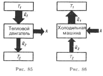 Compared to a heat engine, the processes in a refrigeration machine have the opposite direction. (Fig. 86).
The main purpose of a refrigeration machine is to cool a tank (for example, a freezer). In this case, this reservoir plays the role of a refrigerator, and the environment serves as a heater - the heat removed from the reservoir is dissipated into it.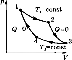
As a result of the outflow of the working fluid from the engine nozzle, a reactive force is generated in the form of a reaction (recoil) of the jet, which moves the engine and the apparatus structurally connected with it in space in the direction opposite to the outflow of the jet. Various types of energy (chemical, nuclear, electric, solar) can be converted into kinetic (high-speed) energy of a jet stream in a rocket engine. R. d. (Engine of direct reaction) combines in itself the engine itself with the propeller, that is, it provides its own motion without the participation of intermediate mechanisms.
All motors have two energy conversion processes. First, the chemical energy of the fuel is converted into thermal energy of combustion products, and then the thermal energy is used to perform mechanical work. Such engines include piston engines of cars, diesel locomotives, steam and gas turbines of power plants, etc.See what "HEAT MACHINE" is in other dictionaries:
Books