Generator
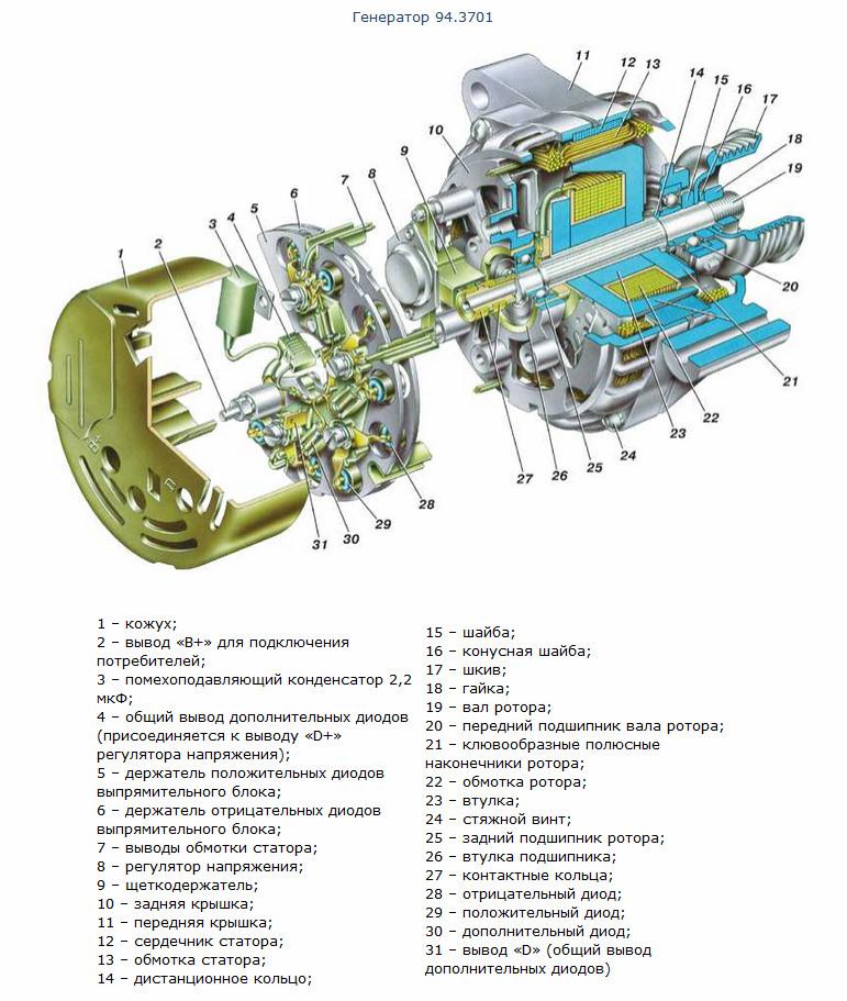
Generator 94.3701
| 1
- casing; 2 - conclusion "B +" for connecting consumers; 3 - noise suppression capacitor 2.2 μF; 4 - common output of additional diodes (connected to the "D +" output of the voltage regulator); 5 - holder of positive diodes of the rectifier unit; 6 - holder of negative diodes of the rectifier unit; 7 - conclusions of the stator winding; 8 - voltage regulator; 9 - brush holder; 10 - back cover; 11 - front cover; 12 - stator core; 13 - stator winding; 14 - distance ring; 15 - washer; |
16
- conical washer; 17 - pulley; 18 - screw; 19 - rotor shaft; 20 – front bearing rotor shaft; 21 - beak-shaped pole pieces of the rotor; 22 - rotor winding; 23 - bushing; 24 - clamping screw; 25 – rear bearing rotor; 26 - bearing sleeve; 27 - slip rings; 28 - negative diode; 29 - positive diode; 30 - additional diode; 31 - terminal "D" (common output of additional diodes) |
Alternator system wiring diagram
"Minus" battery must always be connected to "mass", and "plus" - to be connected to the terminal "B +" of the generator. Erroneous reverse inclusion the batteries will immediately cause increased current through the generator valves and they will fail.
It is not allowed to operate the generator with a disconnected battery. This will cause transient overvoltages at the generator B + terminal, which can damage the generator voltage regulator and electronic devices in the on-board network of the car.
It is forbidden to check the generator's performance "for a spark" even by short-term connection of the generator's "B +" terminal to "ground". In this case, a significant current flows through the valves, and they fail. You can only check the generator using an ammeter and a voltmeter.
It is not allowed to check the generator valves with a voltage of more than 12 V or with a megohmmeter, since it has a voltage that is too high for the valves and they will be punched during testing (a short circuit will occur).
It is forbidden to check the electrical wiring of the car with a megohmmeter or a lamp supplied with a voltage of more than 12 V. If such a check is necessary, then first disconnect the wires from the generator.
It is necessary to check the insulation resistance of the generator stator winding with increased voltage only on the stand and always with the phase winding leads disconnected from the valves.
When electric welding of units and parts of the car body, the wires should be disconnected from all terminals of the generator and the battery.
Generator type 94.3701 - alternating current, three-phase, with built-in rectifier unit and electronic voltage regulator, clockwise rotation (from the drive side).On some of the cars the generator ААК-5102 made in Slovenia can be installed. This generator, in terms of its characteristics and installation dimensions, is interchangeable with the 94.3701 generator, but it has some differences in the arrangement of assemblies and parts. This chapter describes the 94.3701 generator.
Stator and covers 10 and 11 (Figure Generator 94.3701) are tightened with four screws. Rotor shaft 19 rotates in bearings 20 and 25 that are installed in the covers. Power to the rotor winding (field winding) is supplied through brushes and slip rings 27 .
The three-phase alternating current induced in the stator winding is converted into direct current by a rectifier unit attached to the cover 10 ... Electronic regulator 8 voltage is combined into one unit with a brush holder and is also attached to the cover 10 .
The generator wiring diagram is shown in the Generator System Wiring Diagram. The voltage to excite the generator when the ignition is turned on is supplied to the “D +” terminal of the regulator (“D” terminal of the generator) through control lamp 5 located in the instrument cluster. When the ignition is turned on, the lamp should be on, and after starting the engine, it should go out, if the generator is working properly. The bright burning of the lamp or its glow in full heat indicates malfunctions.
After starting the engine, the excitation winding is powered by three additional diodes installed on the rectifier unit of the generator.
Output "W" of the generator is not used on cars of the VAZ-2110 family.
Technical characteristics of the generator type 94.3701
My adventures began three years ago, being in a semi-faint state, I came to the electricians at the service with a problem the battery is discharging - after digging for about 10 minutes under the hood, the electrician issued a verdict Gena died - put a new one, because the way was far, I went to a nearby shop of the rank of an individual entrepreneur (or I don’t remember then there were IPs) and purchased a generator of the KZATE brand (see Figure 1) for 80Ah (a standard generator for the 10th eight-valve Zhiguli family).
fig. 1. Generator KZATE
At first, everything seemed to be fine, but over time, namely six months later, the battery also began to drain. Armed with a multimeter (you can use any voltmeter direct current with a measurement range of 0-20V and a valuable division of at least 0.5-1V) began measuring the voltage (it should be noted that the polarity must be observed during measurements and that the positive terminal of the battery and the car body does not touch, otherwise it may "bite"). Measurement of the battery showed that it was not up to a charge of 12.0 - 12.2V (with the prescribed 12.5-12.8V). I decided to start with a simple check of the voltage regulator - I warmed up the car, put the assistant behind the wheel, forced him to give him 3000 rpm and turn on all consumers - low and high beam headlights, heating rear window and the stove - measured the voltage of 11.5 - 11.7V (should be at least 13.2V), and when the cooling fan was turned on, it sank down to 10.5V. By asking the assistant to turn off all consumers except high beam The headlights measured the voltage again - 11.9-12.1V, although it should be in the range of 13.2-14.7 V. After analyzing the results, I came to the conclusion to replace the voltage regulator (chocolate bar) by purchasing a brand regulator - auto electronics (see Fig. 2a) for 100 rubles and forgot about the problem ...
But not for long, another 4 months passed, the battery was discharged, the measurements were not comforting under a load below 12V, in addition to the chocolate, this time I decided to change the diode bridge (installed in the generator to convert alternating current into direct current, Fig. 2b).
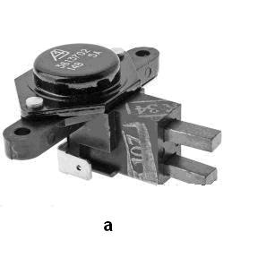
Fig. 2a - Regulator from Autoelectronica
Fig. 2 b - Diode bridge VAZ2110
The diode bridge can be checked in two ways: with and without removing it from the car. Without removing the diode bridge, the voltage regulator is checked by the method proposed by the Za Rulem publishing house. We remove the wires of the battery and generator (including from the output of the voltage regulator) and assemble the circuit according to Fig. 3. A lamp can be used as a control lamp side lights headlights of the tenth family, for the purpose of complete safety of this test, they can be installed on the positive wire fuse 15 or 20A (10A is possible). If a lamp is on, in a circuit assembled according to Fig. 3a, then both the positive and negative diodes have a short circuit, and the diode bridge must be replaced. If a lamp is on, in a circuit assembled according to Fig. 3b, then the positive diodes have a short circuit, and the diode bridge must be replaced. If a lamp is on, in a circuit assembled according to Fig. 3c, then the negative diodes have a short circuit, and the diode bridge must be replaced. Detection of a short circuit of additional diodes is carried out in a similar way according to the following scheme: connect the plus of the battery through the lamp to terminal D of the generator, and connect the minus to one of the phase terminals of the stator winding. If the lamp lights up, then there is a short circuit in the additional diode.
B + - positive terminal of the generator; D- common output of additional diodes
Checking the diode bridge during its dismantling is carried out by checking the diodes using a multimeter when switching it to the appropriate position (Fig. 4). The diode works like a switch - i.e. in one direction alternating current is conducted, in the other not, and since an alternating current flows in a sinusoid, four diodes are needed to rectify it (two are rectified in one half-cycle, two in the other, as a result, the current is constant and not pulsed).
Rice. 4 Diode test function on multimeter
As a result of checks, the diode bridge was found to be in good order, but it was decided to replace it for completeness of the picture.
Having driven into a spare parts store, only the voltage regulator of the Penza plant "Astro" was found in stock (Fig. 5). I would like to express my gratitude to the manufacturer for the good packaging and beautiful logo, but not for their voltage regulator. During the external examination, no special flaws were found, but during the resource test, by moving the generator brushes with the fingers of the hand, they remained in the researcher's palm for a minute.
Rice. 5 Voltage regulator company "Astro" (A) in a plastic case
Having exchanged this product, the voltage regulator and the diode bridge were purchased from another auto shop. But here, too, there were some surprises. When dismantling the old diode bridge and installing a new one, they were not studied and analyzed in detail. On the new diode bridge, there was no gasket (Fig. 6a) of the positive terminal B + (a bolt with a square seat on the head, on which the contact of the interference suppression capacitor is attached (Fig. 6b)). As a result, a short circuit occurred, and the contact of the interference suppression capacitor burned out. Due to the lack of a megohmmeter (for its performance diagnostics), it was decided to replace it, since the price is not high - 25 rubles.
rice. 6a - a - diode bridge view from the reverse side, the place of installation of the generator output gasket B + is indicated
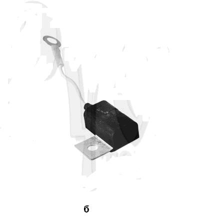
Fig. 6b - noise suppression capacitor
Another three months have passed, the problem of the lack of battery charging has surfaced again at an inopportune moment. This time it was decided not to change the regulator and the diode bridge, but to delve deeper into the study of the "miracle machine". It is worth noting the sagacity of the AvtoVAZ design department, which placed the generator in a place convenient for removal (weak nodes of the eight-valve tenth family in the palm of your hand). Having suffered with the generator clamped in a vice for half an hour, I got to the cherished parts of the "crocodile": the rotor and stator.
Checking the rotor and stator is carried out according to two criteria: checking the windings for an open circuit and checking the windings for a short circuit. I will not describe, because the Internet and technical literature is full of information on this topic. I will only note that when checking the rotor, it is necessary to pay attention to its slip rings (the place where the brushes rest), their diameter should not be smaller 12.8mm, and the marks and grooves on their surface must be cleaned. It is also necessary to check and the height of the brushes, it should be not less 4.5 -5mm.
The rotor and stator were tested by me and were found to be suitable. As a result, without hesitation, I drove into the store and bought a PRAMO brand generator. The only thing that caught my eye when buying was the absence of voltage regulators for this generator on sale (the seller said that they are rare), and they differ from KZATE in design. I have been using this generator for 2 years, and I have no complaints about its work.
Finally some tips from the publishing house "Za Rulem" and from the YouTube channel "Denis Legostaev": 1.
If the main components of the generator are in good working order, but at the same time it has unstable operation
(the indicator lamp periodically lights up, etc.) - this may be caused by poor-quality insulation of the generator winding wire. To eliminate the malfunction, lower it for 2-3 minutes. the rotor and stator of the generator in electrical insulating varnish or boiling drying oil after drying; 2
... If the voltage regulator fails on the way, then its operability can be restored by connecting the output of the voltage regulator "DF" to the "mass" (Fig. 7a) through a lamp of low power 5-8W, for example a lamp side light headlights (or lamps of types A-12-5 or A-12-8). 3
... You can quickly check the generator in the following way: connect the circuit according to fig. 7b, if the generator is in good working order, then when the pulley is turned, the lamp should light up, also pay attention to the slip rings and the operation of the bearings.
The main electrical device that provides power to the VAZ 2110 2111 2112 car while the engine is running is the generator.
Maintenance of the VAZ 2110 2111 2112 generator and the applicability of the generator from Lada Priora.
The guarantee of uninterrupted and reliable power supply to the car is the correct and timely maintenance of the generator. (replacement and adjustment of the alternator belt, brushes, preventive cleaning from dirt and dust). The VAZ 2110 generator has similar electrical output characteristics and connections as the Lada Priora generator, or rather, Priora borrowed the generator from the VAZ 2110 - 2112.
A 94.3701 generator is installed on a VAZ 2110 car. Generators for VAZ 2110 cars are produced by various manufacturers "Fenox", KZATE and others.
|
Figure 1 The structure of the VAZ 2110-2112 generator |
|
| 1
- casing; 2 - conclusion "B +" for connecting consumers; 3 - noise suppression capacitor 2.2 μF; 4 - common output of additional diodes (connected to the "D +" output of the voltage regulator); 5 - holder of positive diodes of the rectifier unit; 6 - holder of negative diodes of the rectifier unit; 7 - conclusions of the stator winding; 8 - voltage regulator; 9 - brush holder; 10 - back cover; 11 - front cover; 12 - stator core; 13 - stator winding; 14 - distance ring; 15 - washer; |
16
- conical washer; 17 - pulley; 18 - screw; 19 - rotor shaft; 20 - front bearing of the rotor shaft; 21 - beak-shaped pole pieces of the rotor; 22 - rotor winding; 23 - bushing; 24 - clamping screw; 25 - rear rotor bearing; 26 - bearing sleeve; 27 - slip rings; 28 - negative diode; 29 - positive diode; 30 - additional diode; 31 - terminal "D" (common output of additional diodes) |
Electrical diagram of the generator system connections on a VAZ 2110-2112 car
Warnings
The "minus" of the storage battery must always be connected to the "mass", and the "plus" - to be connected to the terminal "B +" of the generator. An erroneous re-insertion of the battery will immediately cause an increased current through the generator valves and they will fail.
It is not allowed to operate the generator with a disconnected battery. This will cause short-term overvoltages at the “B +” terminal of the generator, which can damage the generator voltage regulator and electronic devices in the vehicle's on-board network.
It is forbidden to check the generator's performance "for a spark" even by short-term connection of the generator's "B +" terminal to "ground". In this case, a significant current flows through the valves, and they fail. You can only check the generator using an ammeter and a voltmeter.
It is not allowed to check the generator valves with a voltage of more than 12 V or with a megohmmeter, since it has a voltage that is too high for the valves and they will be punched during testing (a short circuit will occur).
It is forbidden to check the electrical wiring of the car with a megohmmeter or a lamp supplied with a voltage of more than 12 V. If such a check is necessary, then first disconnect the wires from the generator.
It is necessary to check the insulation resistance of the generator stator winding with increased voltage only on the stand and always with the terminals of the phase windings disconnected from the valves.
When electric welding of units and parts of the car body, the wires should be disconnected from all terminals of the generator and the battery. Generator type 94.3701 - alternating current, three-phase, with built-in rectifier unit and electronic voltage regulator, clockwise rotation (from the drive side).
On some of the cars the generator ААК-5102 made in Slovenia can be installed. This generator, in terms of its characteristics and installation dimensions, is interchangeable with the 94.3701 generator, but it has some differences in the arrangement of assemblies and parts. This chapter describes the 94.3701 generator.
Stator and covers 10 and 11 (rice. Generator 94.3701) are tightened with four screws. Rotor shaft 19 rotates in bearings 20 and 25 that are installed in the covers. Power to the rotor winding (field winding) is supplied through brushes and slip rings 27 .
The three-phase alternating current induced in the stator winding is converted into direct current by a rectifier unit attached to the cover 10 ... Electronic regulator 8 voltage is combined into one unit with a brush holder and is also attached to the cover 10 .
The generator wiring diagram is shown in fig. Alternator system wiring diagram... The voltage to excite the generator when the ignition is turned on is supplied to the “D +” terminal of the regulator (“D” terminal of the generator) through a test lamp 5 located in the instrument cluster. When the ignition is turned on, the lamp should be on, and after starting the engine, it should go out, if the generator is working properly. The bright burning of the lamp or its glow in full heat indicates malfunctions.
After starting the engine, the excitation winding is powered by three additional diodes installed on the rectifier unit of the generator.
Output "W" of the generator is not used on cars of the VAZ-2110 family.
Technical characteristics of the 94.3701 type generator installed on a VAZ 2110-2112 car, Lada Priora
The generator on any machine, including the VAZ 2110, is a device designed to convert mechanical energy into electrical energy. Thanks to this unit, all electrical equipment of the car is powered while driving. More about the principle of work, technical characteristics ah and connecting the device, you can learn from this material.
Description of the device
To begin with, consider the generator design. Regardless of which node we are talking about - old or new, it includes many different elements. More detailed description shown in the figure below. For the VAZ 2110, the Katek device is initially installed from the factory.
Principle of operation
As for the principle of operation of Katek or any other device, the following is:
- When the key is turned in the ignition lock, voltage begins to flow to the excitation wire.
- The anchor comes into operation and when it reaches high frequency rotation, provided by a belt drive and a pulley, a self-excitation mode is formed.
- Further, the AC voltage is converted to DC by means of a rectifier unit.
- 3-level 2110 comes into operation after the speed changes crankshaft... The three-level regulator adjusts the time at which the excitation wire is activated.
Functions performed
The generator on the VAZ 2110 with a 3-level regulator is designed primarily to ensure the operability of all electrical equipment of the car. If you think that this function is performed by the battery, then you are wrong. The battery is designed to maintain the operation of the equipment when the engine is off, while the VAZ 2110 generator operates at running engine... So it is this node that ensures the operability of all devices, an air conditioner, a stove and other gadgets that you connected to the car's on-board network.
Another function of a unit with a 3-level or other regulator is to charge the battery, which is also carried out when the engine is running. If it were not high enough, the battery would not be able to perform the tasks assigned to it, as a result of which it would have to be constantly recharged. But it should be noted that high power can be provided by setting the node to 120 amperes.
It should be noted that in addition to a more powerful generator unit, it makes sense to put an injector on the VAZ 2110. Especially if the battery is discharged quickly enough when additional consumers are turned on. A three-level voltage regulator will solve this problem (video author - Denis Legostaev channel).
Technical specifications
Now let's look at the main technical characteristics. As mentioned above, during production, "dozens" are equipped with Katek devices, which can be of two types. But regardless of the type, such mechanisms have a power of 80 Amperes, and the level of voltage they produce is about 14 volts. Also on sale you can find more powerful Katek options - 120 amperes - which are designed for use in cars with higher loads.
Device components
The main components of the node:
- An anchor, which is a rotating part of the device and is designed to create a magnetic field.
- Stator including 3 windings.
- Two-piece body made of aluminum alloy.
- Fastening the device to fix it in engine compartment.
- Brush assembly. Please note that brushes are, in fact, consumable as they wear out over time.
- The voltage regulator of the VAZ 2110 generator is 3 or less levels. The purpose of this element is to change the voltage that goes to the battery. If the temperature is higher, less voltage is applied to the battery.
- A rectifier unit with diodes, the purpose of which is to convert the alternating current generated by the armature into direct current. Constant pressure, in turn, is used by all electrical equipment of the car.
- Belt drive to increase crankshaft speed.
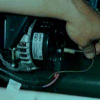
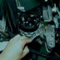
Removal and Installation Guide
It is not so difficult to dismantle and install a new device at home.
The generator connection diagram and the connection of all components are as follows:
- De-energize first on-board network auto, to do this, open the hood and disconnect the battery.
- Then locate the generator set in the engine compartment and disconnect the excitation cable from it.
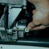
- Using a 10 wrench, you need to unscrew the nut that secures the two wires to the "B +" terminal. When the nut is unscrewed, the wires can be disconnected.
- Next, you need to dismantle the strap. If his condition is deplorable, then the belt needs to be changed in order to prevent it from breaking at the most inopportune moment. Replace the strap if it shows signs of damage, such as cracks or other signs of wear. Unscrew the mechanism adjusting screw, then you can unscrew the fixing nut.
- After these steps, you can remove the tension bar of the assembly.
- Using a 13 wrench, you can unscrew the nut that secures the lower mount of the assembly.
- Remove the screw and dismantle the device from the car. Further installation of the new unit is carried out in the reverse order.
Issue price
If you need to buy a new generating unit, then you need to take into account that its cost varies not only depending on the manufacturer, but also on the technical characteristics. The more powerful the generator is, the more expensive it will cost.