Control module force aggregate (PCM) Ford Focus
Fig. 3.159. Power Unit Management Module (RCM):
1 - PCM EEC V; 2 - inertial fuel supply cut-off (IFS)
RSM is located under the finish panel on the right rack "A".
On cars Ford Focus With automatic transmission RSM.
EEC V controls the gearbox, as well as the engine control system. In this case, a module with a 104-pin connector is used.
RCM estimates the input signals coming from individual sensors and activates the solenoid valves in the gearbox valves block exactly according to the working state.
Diagnostic checks of the gearbox can be performed through the data channel connector (DLC) located above the central electrical distribution box (CJB).
Range selection - emergency work program.
If due to the receipt of incorrect signals can not be guaranteed correct gear shifting, RSM starts working in the emergency work program mode.
The driver learns about the action of the emergency working program for sunbathing on the instrument panel of the control lamp of the force aggregate.
Continuous monitoring is guaranteed in the following limited states:
— maximum pressure in the main highway;
- 3rd transmission when finding a manual gear lever in the positions "D", "2" and "1" without activating the blocking clutch of the hydrotransformer;
- Transfer rear stroke When finding a manual gear selection lever in the "R" position.
Electromagnetic control of synchronized transmission (ESSC).
Switching control
When switching gear, certain elements are released, while others are entered into operation. Ideally, this process occurs simultaneously (synchronously) to avoid jerking when switching.
The duration of the gear shift process should remain within the time limits of the time range.
With normal transmission switching, the increase and reduction of pressure in the switching elements is configured and determined for ideal conditions (for synchronous switching).
Because The method affects the control in the case of varying degrees of wear of the switching elements in cases where the gearbox has worked a very large resource, it is not possible that the increase and reduction of pressure will not occur synchronously.
The result of a premature pressure reduction in the off element is an undesirable increase in the frequency of rotation of the turbine shaft, because The included item cannot transmit the primary torque.
The result of the discharge reduction of pressure in the off element is an undesirable decrease in the rotation frequency of the turbine shaft, because Both switched elements transmit torque. In this case, the torque is transmitted to the Gearbox Carter using the internal lock.
In both cases, twitching will be felt when switching.
In addition, wear in the switching elements leads to an increase in the duration of the switching procedure. Therefore, as the service life of the gearbox increases (increasing the mileage), switching becomes more and more prolonged.
Switching control using ESSC.
AT automatic box Gear 4F27E Used electronic control synchronized switching (ESSC).
ESSC controls the operation of switching and can compensate for the wear of switching elements throughout the entire life of the gearbox.
This became possible because switching elements are activated by modulating valves.
The system controls the switching time and shift synchronization.
If PCM determines the deviation from the values \u200b\u200brecorded to the memory for switching and synchronizing the switching process, an increase in or decrease in pressure will be adjusted accordingly.
Throttle Position Sensor (Tr)
The trot sensor is located on the throttle housing.
It supplies RSM information about the position of the throttle.
It also determines the speed of using throttle.
- definitions of switching order;
- pressure management in the main highway;
- To work the "Kickdown" function (shifting gear when you press the accelerator pedal).
In the absence of a signal, the engine control uses MAF and IAT sensor signals. The pressure in the main highway increases, and it may arise a rigid gear.
Air Flow Sensor (MAF) and air intake temperature sensor (IAT)
The MAF sensor is located between the air filter housing and the air intake hose, which goes to the throttle housing.
The IAT sensor is embedded in the MAF sensor housing.
The MAF sensor, together with the IAT sensor, supplies the primary load signal to PCM.
The RCM uses these signals to perform the following functions among other things:
- switching control;
If the MAF sensor fails, the sensor tr.
Position sensor crankshaft (UKR)
The SCR sensor is located on the engine flange / gearbox.
The CRR sensor is an inductive sensor that supplies the RSM information about the rotational speed of the engine and the position of the crankshaft.
- control of the locking coupling of the hydrotransformer;
- check validation of the hydrotransformer;
- pressure management in the main highway.
The replacement signal for the SDR sensor is missing. If there is no SCR signal signal, the engine stops.
Turbine Shaft Rotation Sensor (TSS)
The TSS sensor is located in the gearbox crankcase over the primary gearbox shaft.
TSS sensor is an inductive sensor that perceives the speed of rotation. primary Vala Gearbox.
The signal is used to perform the following functions:
- switching control;
- control of the locking coupling of the hydrotransformer;
- Checking the slip of the hydrotransformer.
If the TSS sensor fails, a secondary shaft rotation sensor signal (OSS) signal is used as a substitution.
Secondary Shaft Rotation Sensor (OSS) 
Fig. 3.160. Secondary Rotation Speed \u200b\u200bSensor
The OSS sensor is located in the gearbox crankcase over the rotor in the differential.
The OSS sensor is an inductive sensor, which is using a rotor existing in the differential determines the vehicle speed.
The signal is used to perform the following functions among other things:
- definitions of switching order
- supply the input signal of the velocity of the car to the RSM.
If the OSS sensor fails, the TSS sensor signal is used as a substitution.
Transmission Range Sensor (TR)
The trial sensor is located on the hand shaft on the gearbox crankcase.
When the manual shaft is moved by using the manual selection cable, the hook pin in the inner ring of the TR sensor moves through various positions. Signals are transmitted to RSM, reverse lamps and starter lock relay.
Note, the correct action of the TR sensor is guaranteed only when the manual selection lever cable is properly adjusted.
TR sensor signals are used to perform the following functions: 
Fig. 3.161. Transmission Range Sensor (TR)
- Recognition of the position of the manual gear lever;
- activation of the starter lock relay;
- turn on the reverse lights.
The replacement signal for the TR sensor is missing.
In case of rupture of the electrical circuit, the car will not be able to run.
Stop Signal Switch
Stop signal switch (brake pedal position switch (VRP)) is located on the brake pedal bracket.
It includes stop signals and reports RCM EEC V on the activation of the brakes.
The stop signal switch signal is used by PCM to perform the following functions:
- release of the blocking clutch of the hydrotransformer when the brake pedal is pressed;
- shutdown blocking the switching of the manual gear lever when you click on the brake pedal in the "P" position.
The replacement signal for the VRR switch is missing.
In case of rupture of the electrical circuit of the VRR switch, the manual gear lever cannot be derived from the "P" position.
temperature sensor transmission fluid (TFT)
The TFT sensor is located on the inner wiring harness, which goes to the electromagnetic valves of the oil crankcase.
This is a resistor that measures the temperature of the transmission fluid. 
Fig. 3.162. Accelerating Transmission Switch (O / D)
Information on the temperature of the transmission fluid is used by PCM to perform the following functions:
- activation of the clutch of the hydrotransformer is not allowed until the temperature of the transmission fluid reaches a certain temperature;
- in conditions of an extremely low negative temperature, the inclusion of the 4th gear is not allowed until the normal operating temperature is reached;
- when the temperature of the transmission fluid is exceeded, a given fixed gear shift curve is selected, and the torque converter blocking clutch is activated in the positions "2", "ZM and" 4M; Activised control lamp Gearbox. The replacement signal for the TFT sensor is missing.
Accelerating Transmission Switch (O / D)
The O / D switch transmits a RSM signal to select or disable the selection of the 4th gear when the manual gear lever is found in the "D" position.
O / D Switch Signal is used to perform the following functions:
- as an input signal to transfer the desire of the driver of PCM;
- To display the driver's desire using the O / D control lamp on the instrument panel.
The replacement signal for the O / D switch is missing. If it is faulty, it is always possible to switch to the 4th gear when the hand selection lever is found in the "D" position.
Electromagnetic shift locking lever manual gear lever
When the ignition is turned on, the electromagnet of the switching lock of the manual gear lever is activated by pressing the brake pedal (signal from the stop signals). This leads to an accumulation of the locking pin, and thus the manual gear lever can be derived from the "P" position. 
Fig. 3.163. Electromagnetic shift lock for manual gear lever:
1 - electromagnet; 2 - blocking pin; 3 - manual locking mechanism
Replacement function
If due to improper functioning, the signal from the brake does not arrive or invertible, it is possible to manually remove the lock. 
Fig. 3.164. Replacement function
To do this, remove the release mechanism cover and insert a suitable object (ignition key) into the hole so that the manual gear lever can be derived from the "P" position.
Note: If the "P" range will be selected again, the manual gear lever will be blocked again. Air conditioning
If the RSM registers the "Kickdown" signal (shifting the gear when you press the accelerator pedal) (WOT, throttle valve Opened by 95%), the air conditioning system is turned off, maximum, 15 s.
Starter lock relay
The relay prevents the engine launch when the manual gear lever is in the "R" position, "D", "2" or "1" position.
The relay receives information about the position of the gear selection lever directly from the TR sensor.
Ignition keys lock electromagnet
The electromagnet is built into the ignition lock. When the gear selection lever is in the Position "P", the electromagnet earth chain is bursting. The blocking pin is not fixed in the ignition lock.
In all other positions of the manual transmission lever, the grounding circuit of the electromagnet is closed and the locking pin is fixed in the ignition lock.
When the hand selection lever is in a position other than "P", it is impossible to extract the key from the ignition lock.
O / D control lamp
The O / D control lamp is a green light indicator located on the instrument panel. 
Fig. 3.165. O / D control lamp
It informs the driver that the transmission control blocks the switch to the 4th gear.
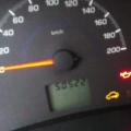
Control lamp of the power unit
The control lamp of the power unit is a lamp of an orange color located on the instrument panel. 
Fig. 3.166. Check Check Power Unit Check Lamp
Its inclusion informs the driver that the transmission control switched to the emergency work program, or that the temperature of the transmission fluid is too high.
manual Ford Focus Manual
Fuel injection system
The fuel injection system consists of three subsystems, which, working together, control the combustion process and provide feedback on operating efficiency. These subsystems:
1. Air intake
2. Fuel supply
3. Fuel Management
The air intake system provides air supply required for the combustion process, and measures the amount of air included in the engine. Typical elements include air intake, air filter, inlets, meter (or sensor) of air flow (or mass) and other special elements of the air intake system.
The fuel supply system serves gasoline from fuel tankFilters it and sues high pressure to the engine. The system elements includes a fuel pump, fuel filter, fuel collector, fuel injectors, pressure regulator and pulsation damper. On engines with a closed fuel circuit, the system also includes a fuel line that returns unused fuel to the tank (return fuel line).
In the fuel consumption management system, there are input sensors that perform continuous measurements and transmit this information to the engine control computer. The computer determines the amount of fuel for injection and uses output actuators to activate the fuel injectors at a precise period of time. The operation of the engine control computer is discussed in more detail on.
The computer makes several thousand calculations per minute and constantly adjusts the amount of fuel as the movement conditions change. These processes go continuously since the engine start. Fuel injection is based on an extremely accurate measurement of the amount of encompade air. Any failure that will not allow you to get this information will lead to the fact that the computer will give an incorrect estimate of fuel injection parameters.
The computer calculates the amount of fuel injected, based on the input signals obtained by them, reporting air flow, its mass and temperature of the air intake.
Engine management system
Engine control system is controlled on-board computerwhich is called different manufacturers in different ways. Below are the two most common names of this computer:
Power Unit Management Module (RCM)
. Engine Management Module (ECM)
In this publication, the engine controller is mentioned as RCM.
RSM is the heart of the modern engine control system. It controls the ignition system, fuel injection system and other elements. RCM is intended to increase the efficiency of the engine and reduce the toxicity of exhaust gases
RCM retains the stoichiometric ratio of "air / fuel" in conditions of movement at economical speed. However, the conditions of movement change, and the stoichiometric air-fuel mixture will not be ideal for all conditions. Depending on the working conditions of the RCM makes the air-fuel mixture richer or poorer.
RCM receives information from the input sensors and sends control signals to the corresponding output devices, such as fuel injectors. The location of the PCM and sensors depends on the model and the manufacturer. For information on the location of the elements, always refer to the manual for maintenance stations.
PCM input devices
Input sensors are continuously served detailed informationassociated with various aspects of the car's work. The following section describes sensors characteristic of modern Systems Management of the power unit.
Ignition pulse signal
RSM receives a ignition pulse signal from the ignition coil and on the basis of this signal sets the amount and fuel injection advance.
Engine coolant temperature sensor
Robes of air-fuel mixtures compensate for poor fuel evaporation at low temperature. RCM controls the temperature of the coolant and increases the fuel injection volume to improve the total dynamic characteristics of the car during a cold engine.
The engine coolant temperature sensor (eats) measures the temperature of the cooling fluid to change the electrical resistance. The thermistor changes its electrical resistance in accordance with the temperature change.
Air temperature temperature sensor
The air intake temperature sensor (IAT) is a thermistor. It is located in the engine air intake system and serves to determine the temperature of the incoming air. The IAT sensor supplies a voltage signal varying depending on the resistance. Sensor resistance and the resulting sensor voltage is high when the sensor is cold. With increasing temperature, the resistance and the sensor voltage decreases.
Crankshaft position sensor (UKR)
RSM uses the engine crankshaft rotation frequency to help set a basic injection. The crankshaft position sensor (UKR) can be located on the crankshaft or inside the distributor.
Near the sensor quickly rotates a special rotor (pulse wheel), equipped with protrusions or teeth and located on the crankshaft. The sensor registers the change in the magnetic field strength with each passage of the protrusion next to it.
Engine crankshaft rotation frequency sensor
The engine crankshaft rotation frequency sensor, mounted in the distributor, or the crankshaft rotation angle sensor can be a disk type or device whose work is based on the Hall effect.
In the disk type sensor, a disc with slots mounted on the distributor shaft, two LEDs and two photodiodes are used. One LED indicates an angle of rotation of the crankshaft, while the second LED indicates the position of the cylinder.
Position sensor distribution Vala (CMR)
RCM uses a camshaft position sensor (CMR) to track the position of all cylinders and controls fuel system and ignition system. The sensor registers the position of V.M.T. During the compression for the cylinder 1 1 and can be located in the distributor or near the camshaft. The SMR sensor registers the magnetic field strength changes caused by protrusions on the camshaft pulley.
Car speed sensor
Car speed sensor (VSS) Indicates vehicle speed. There are three common types of VSS sensor - sensors of the generic relay and type of optocrons are in the speedometer, and the electromagnetic type sensor is on the secondary gearbox.
Some car manufacturers for information about the velocity of the car also use a wheel speed sensor that is part of anti-lock system brakes.
Oxygen sensors
The anterior oxygen sensor measures the oxygen density in the exhaust gases and gives the corresponding signal to the RSM. The front oxygen sensor is located in front of the catalytic neutralizer. RSM uses the input signal from the front oxygen sensor to calculate changes in the "air / fuel" ratio.
In addition, there is a rear oxygen sensor installed for a catalytic neutralizer. RSM compares signals from two oxygen sensors to control efficiency catalytic neutralizer And the definitions, the catalytic converter works correctly.
Throttle Position Sensor (TPS)
The throttle position sensor (TPS) is a varistor (potentiometer) installed on a throttle valve. The throttle housing opens and closes by means of a cable that connects to the accelerator pedal. When the throttle is closed, the computer removes the low voltage signal. When the throttle is wide open, the computer removes the high voltage signal.
Mass Air Flow / Air Flow Sensor
The mass flow sensor (MAF) measures the volume and density of incoming air. When performing measurements, the MAF sensor is able to take into account the temperature, density and humidity of the air. All these parameters, taken together, determine the "mass" of incoming air. The computer uses information about the actual mass consumption of air, which helps to calculate the "air / fuel" ratio.
Other input devices
Depending on the manufacturer of the car there are several other input devices. The following input devices may include the following:
Sensor absolute pressure In the intake manifold (MAP) - measures changes in air pressure in the intake manifold.
. The detonation sensor - sends a RSM signal to a decrease in the angle of the ignition advance in the case of increased detonation.
. Parking / Neutral Position Switch (P / N) - reports PCM, is the gearbox in the position of parking transmission or in a neutral position or one of the movement gears.
. Steering power switch (with a crankshaft rotation frequency in idle mode) - Used to register high pressure working fluid In the steering amplifier system.
. High-pressure relays A / C - sends to RSM "Request" to turn on A / C so that the PCM can turn on the A / C compressor.
. Cruise control switch - when the RCM receives a cruise control signal, it retains the desired value of the speed in memory, which makes it possible to save this speed.
Output actuators open and closed valves, injected fuel and perform other tasks, responding to control signals coming from PCM. Some actuators are managed while others simply turn on or off. The length of the time during which the actuator works, is its working cycle. RSM manages working cycles and, depending on the need, can or extend or reduce them.
Fuel injectors
Fuel is supplied to the engine by fuel injectors. Fuel nozzles control RSM. Continuous fuel supply under pressure in the fuel injector is performed fuel pump. Fuel burner - this is an electromagnetic valve that is activated when the electrical circuit is provided on the "mass", and after that the fuel under pressure is "injected" in intake manifold. The computer controls the flow of fuel by means of a latitude and pulse modulation of the time of the nozzle turned on. The time of the nozzle was turned on is determined by the combination of previously described input signals of PCM.
Air supply control valve in idle mode
The air supply valve in idling mode (IAC) is located in the throttle housing. The IAC valve consists of a movable needle that is controlled by a small electric motor, called a stepping motor. The stepper electric motor is capable of moving, performing very accurate, measured "steps". The computer uses the IAC valve to control the crankshaft rotation frequency in idling mode. The IAC valve changes the position of the needle in the idle air channel in the throttle housing. Then the nature of the incoming air flow near the throttle is when it is closed, changes.
Electric fuel pump
In most fuel injection systems, an electric fuel pump is built into the tank. When the ignition switch is activated, the computer, applying the battery voltage, excites the relay that controls the fuel pump. The relay remains on until the engine starts to turn the engine or the latter will not start working and the computer will not receive the base impulses. If there are no basic pulses, the computer turns off the relay.
Electric fan cooling
Under certain conditions, for cooling the radiator and / or capacitor A / C, single or doubles are used. electric fans cooling. On most options, the cooling fans are controlled by PCM. In computer-controlled versions, the cooling fan relays are used. The computer provides a grounding of the cooling fan relay on "mass", feeding the system voltage to the electric motor of the cooling fan when some or all conditions are followed:
Cooling fluid temperature sensor indicates a high cooling fluid temperature
. The activation of the system A / s is requested. A / C included, and the speed of the car is below the specified
. Pressure on the high pressure side A / C above the specified value, it is possible to open the high pressure relay
Wrong work lamp
The control lamp of the engine maintenance or control lamp of the wrong operation (MIL) is lit when the ignition key turns into the on-line (ON) when the engine is not working. Do not worry about this because it is only fast check Lamps. When the engine is running, MIL is usually lit. If the malfunction code is saved in the memory, or the computer enters the backup mode, MIL lights up, which means that there is a grounding of the MIL electrical circuit. If the status changes and the code (or codes) of the fault is no longer present, the lamp can go out, but the code remains in the memory of the computer.
Side diagnosis
RSM contains diagnostic software that controls the operation of the car and registers the faults. This software is referred to as onboard diagnostics (OBD).
In 1994, manufacturers began to equip RSM cars containing second-generation side diagnostics system (OBD II) or EOBD for Europe. Software controls those parameters in fuel injection systems and lowering the exhaust toxicity that can cause an increase in exhaust toxicity. In addition to checking for malfunction of the elements, OBD II checks and tests the correctness of the subsystem. In addition, it monitors the deterioration of the operations of sensors and actuators.
Management of fuel pressure regulator
In some RCM engines, the fuel pressure increases to prevent the formation of "steam plug" (boiling) when the engine temperature is high. For example, if the coolant temperature at startup is 212 ° F (100 ° C) or higher, the PCM activates the electromagnetic pressure control valve of the pressure regulator.
When the solenoid valve works, the vacuum supply to the pressure regulator decreases, forcing the fuel pressure becomes higher than for the usual engine operating conditions. Solenoid valve It remains activated for a short time after starting the engine.
Basic idle system
Bypass allows some air intake manifold in the intake manifold when the engine is operating in idle mode, because the throttle is almost completely closed. The iac valve controls the "bypass" air necessary to stabilize the rotational speed of the crankshaft in idling mode at various loads (A / C, electrical load, steering amplifier, etc.). The IAC valve, which is an executive device of an electromagnetic type, is activated by PCM. This valve provides accurate control of the amount of air that bypass the throttle.
In some cars to control the basic idle A combination of two valves is used: mechanical and electromagnetic. When starting from the cold state, both valves are open, which provides additional air intake when starting and warming up. As the coolant temperature increases to normal, the mechanical valve is gradually closed, and the air passes only through the solenoid valve.
For reprogramming PCM blocks, three things are required:
- scanner or universal device J2534, capable of working with flash memory,
- windows operating system,
- PC with Internet access to download software from the site of the automaker
A cable for connecting a PC to a scanner or a J2534 device and a cable for connecting a scanner or device J2534 to a car OBD II connector.
To download the programs you will need to choose from: the factory diagnostic device that dealers use the scanner (it can be purchased in retail) with the ability to reprogram the block of the corresponding car model or the Universal device J2534.
An annual or monthly subscription to the use of OEM databases is quite expensive for a small service station, but the cost of a one-day or short-term subscription ranges from about $ 20 - $ 25. These costs are usually shifting the "on the shoulders" of the car owner if online access to the program database at the service station is required.
As for Generl Motors and Chrysler programs, the updates are supplied on CDs after purchasing a subscription. Then the program can be copied to the flash card and upload to the scanner for the subsequent installation in the car control unit or copy to the J2534 unit and then install on the car. Ford programs are downloaded from the company's website. When working with them, constant access to the Internet is required during the execution of the reprogramming procedure, since according to the company's rules, loading programs into the car is carried out directly from its own Ford Server.
The reprogramming procedure can take from a few minutes to an hour depending on the size of the program file that is installed on the car. On more modern cars With complex systems, it is usually required more time to reprogram the PCM block.
Warning!
Reprogramming PCM block is associated with risk
What happens in case of incorrect reprogramming? Anyone who establishing a new software faced with a collection when installing, understands what it is. In some cases, PCM can receive such damage that the recovery is not subject to the purchase of a new PCM!
Chrysler notes TSB (18-32-98), how to eliminate reprogramming error.
The bulletins say that "the reprogramming procedure may not be completed correctly and / or the diagnostic device can be blocked during the reprogramming process." It is mainly due to a bad connection between the PC, the scanner and the car, the power loss of the diagnostic device during the reprogramming process, turn off the ignition before the reprogramming procedure is completed, errors (incorrectly by pressing the buttons) or low battery charge.
If the process is stopped, you should double-check all wire connections to ensure the reliability of connections and re-conduct the reprogramming procedure. In other words, if it did not work from the first time, you must try again and again. In Chryslera, it may also be necessary to identify the type of controller (SBEC2, SBEC3, JTEC 96-98, JTEC + 99, etc.) to begin reprogramming. If an error message appears again, it is possible that the wrong type of controller is selected (attempt again!).
Reprogramming is a risky undertaking.
But it may be more profitable than sending a car to the dealer to replace RSM.
1. Disconnect the battery mass.
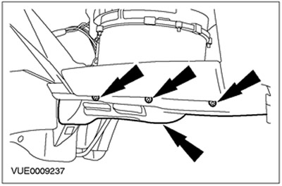
2. Remove the side decoration of the instrument panel.
3. Remove the front door opening panel.

Cars with right-hand control
4. Remove the lower section of the instrument panel. Disconnect the data channel plug connector.

Left-dialing cars
5. Remove the "PC".

6. Remove the bottom section of the instrument panel finishes.
7. Disconnect the plug connector of the central security module (CSM).

8. Disconnect the fastening bracket of the power unit control module (RSM).

9. Disconnect the general electronic modular module (GEM) from PCM and place it aside.
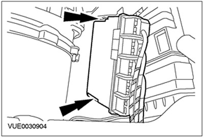
10. Disconnect the PCM from the support bracket.
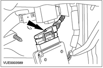
All cars
11. Disconnect the PCM.

12. CAUTION: Before starting drilling, protect the floor covering. Disclaiming this instruction may result in damage to the flooring.
Drill the guide hole with a diameter of 3 mm in the center of the welded nut.

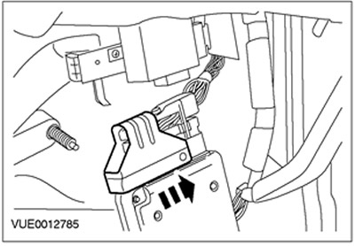
13. Drill the hole with a diameter of 8 mm in the welded nut to release the cutting bolt.
- Remove the cutting bolt and relent it for further inappropriate.

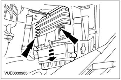
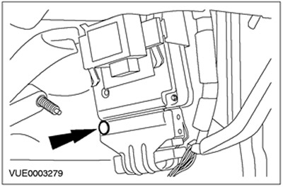
14. Remove the PCM protective bracket and releave it for further unnecessary.

15. Remove the PCM plug connector.
16. Remove RCM.
Installation
All cars1. Dock PCM plug connector.

2. Note: Install the new PCM bracket.
Install PCM Protective Bracket.
3. Note: Install the new PCM protective bracket bolt.
Install the PCM Protective Bolt Sliced \u200b\u200bBolt.
4. Install PCM.

Cars manufactured up to 10.2001
5. Connect the PCM mounting bracket.

6. Docine CSM plug connector.

Cars manufactured from 10.2001
7. Connect the GEM module to PCM.