The idea to equip my car with an additional speedometer came to me as soon as my ABS failed. And we drove the whole vacation without an ABS and a speedometer. Now I have a new ABS unit and the speedometer also works. On most new cars, all the ABS type electronics and all kinds of movement controllers are tied to one unit. For some, in general, when it fails, the speedometer does not seem to be exactly, and the whole panel does not work. And sometimes it doesn't even start. It's good that my car is not one of those.
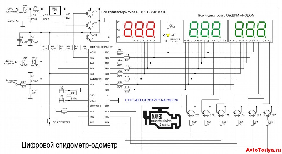
From the speedometer circuits found on the Internet, I liked the circuit on the PIC16F628A microcontroller.
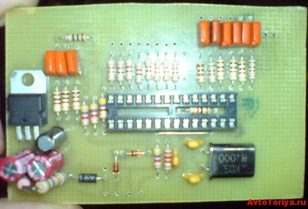
circuit 1 PIC16F628A
The speedometer is based on the PIC16F628A microcontroller. Any LED indicators with a common cathode are suitable as information display devices. I used a small three segment indicator. When using other indicators, you may have to select current limiting resistors in the anode circuit. The device is connected to the signal contact of the standard speedometer. By pressing the SB1 button (duplicated by sound), you can change the brightness of the indicators "in a circle". Each time you turn it on, the brightness of the indicators is set to what it was previously set. Any sound emitter HA1 with a built-in generator capable of operating from a 5 volt power source. With a loosely closed car door (signal low level relative to the hull) and a speed of more than 9 km per hour, an intermittent signal is heard, and the speed reading on the indicator is replaced by the abbreviation 'dor' turned on at full brightness (abbreviated from the English "door" - door).
The used firmware of the microcontroller is universal, which allows you to choose one of five options for the speedometer, depending on the number of pulses coming from the vehicle speed sensor. The proposed digital speedometer “understands” the sensors that issue: 2500 imp / km, 4000 imp / km, 6000 imp / km, 8000 imp / km and 10,000 imp / km. The list can be expanded by making appropriate changes to the program. Let's say, if the vehicle speed readout is taken, integrated from all four wheels. And the signal can be taken from one of the wheel sensors.
And so to select the desired option, you need to set the S1 jumper and then apply power to the device. When the jumper is installed, the indicator is off. Now, by pressing the SB1 "Brightness" button (for 1-2 s, with a pause between presses 1-2 s), the desired option is selected:
1 press - 2500 imp / km;
2 clicks - 4000 imp / km;
3 clicks - 6000 imp / km;
4 presses - 8000 imp / km;
5 clicks - 10000 imp / km.
3 seconds after the last press, the corresponding number of short sound signals emitter HA1, confirming the entry in the EEPROM of the microcontroller of the desired version. The default mode for the speed sensor is 2500 imp / km. And when the number of taps is more than 5, the Japanese standard (2500) will also be set. To select another operating mode, it is enough to repeat the above steps. After selecting the desired operating mode, the S1 jumper must be removed. The speedometer is now ready for use.
The reading error is for:
1 option (2500) +0.2 km;
2 options (4000) less than 0.1 km;
3 options (6000) +0.2 km;
4 options (8000) - 0.4 km;
5 options (10,000) less than 0.1 km;
Regardless of how the vehicle speedometer (CA) shows on dashboard speed - in kilometers or miles, this device is one of the most important. In particular, any driver most often looks at him while driving. You can learn more about the purpose, varieties, as well as the error of readings from this article.
Appointment
The driver is forced to pay attention to the speedometer readings due to the fact that speed limits are in force in every country today. Moreover, they can vary significantly depending on the section of the road on which the car travels. The designation of the driven speed in the car is one of the main purposes of the device. It should also be noted that its kit includes an odometer - a device for measuring the distance traveled by a car, and if this device is electronic by its type, it will also show the mileage of one trip.
In addition, with the help of this device, the car owner will be able to determine when to change motor fluid or filters in the car. The readings of the speedometer, in particular the odometer, will help determine the fuel consumption, if everything is calculated correctly. It doesn't matter if the car's speedometer shows the speed in miles or kilometers.
Device types
We figured out what the speedometer shows and what the speedometer scale is for, now let's talk about the types of devices. If the device is a pointer, then the speedometer needle will measure the speed using a mechanical indicator. If electronic, then the speedometer needle is not used in this case, since all indicators will be displayed on a special screen.
- Devices of a mechanical type, in this case, the principle of operation of the speedometer is based on the speed of the cable from the gearbox. The speedometer cable is one of the main structural components. Currently, this type of device is almost never used, since the error of the speedometer can be more than 15%.
- An induction type device consists of several elements. One of them measures the speed of movement, and the second - the mileage of the car.
- Electromagnetic SA. In this case, the speed sensor will transmit electrical signals, and the speedometer drive itself will move in accordance with the number of signals.
- The most modern version the CA is considered to be linked to a GPS navigator - this option allows the most accurate speed measurement.
Device and principle of operation
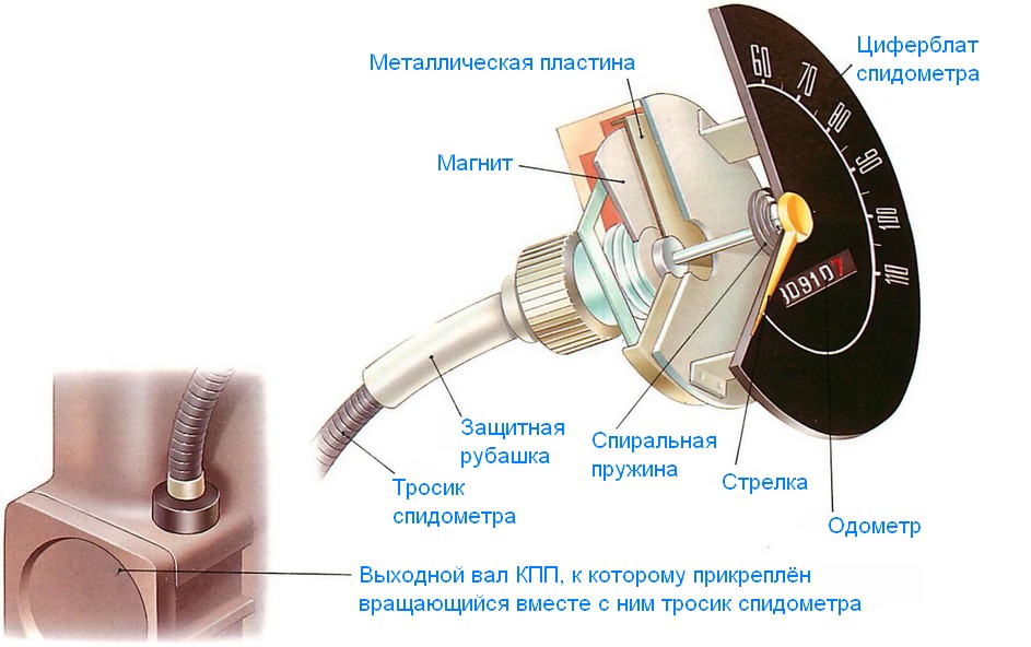
Now let's figure out how the speedometer works using the example of a mechanical device. In this case, the speed measurement is carried out due to the mechanical connection between the pointer and the gearbox output shaft. The speedometer reducer and the pointer are linked by an element such as a speedometer cable. Since the shaft itself is located further along the chain from the transmission, the speed of its rotation is determined by the final speed of rotation of the wheels (the author of the video is the channel Ruslan Yunyaev).
The transmission itself has a special gear. The drive gear of the speedometer drive rotates simultaneously with the output pulley and is also connected to the cable. The speedometer cable itself is a strong rotating wire, enclosed in a special casing, one end of which is mounted on the gear, and the other inside the device, on the arrow. When the speedometer gear rotates, the corresponding rotation occurs with the cable.
At the second end, which is located in the device, there is a special magnet in the form of a disk, which is installed in close proximity to the steel drum. It should be noted that these elements are not interconnected. The drum itself is fixed on the needle, and the readings obtained are displayed on a scale. More details on how the photo speedometer works is presented below.
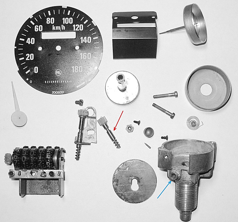
The speedometer device is as follows:
- speedometer drive;
- magnet;
- thermomagnetic element;
- scale;
- spiral spring;
- arrow;
- steel plate;
- protective cover;
- cable.
Reading error
The CA itself is a configurable instrument, but it cannot be 100% accurate. Like any other measuring device, the CA has a certain error and usually the device overestimates the speed indicators, but does not underestimate them.
To begin with, for those who have forgotten what a speedometer is. A speedometer is an auto device that measures your speed. You can install a speedometer in your car both purchased and made with your own hands. Well, how to make an electronic speedometer with your own hands - you ask? It turns out that there is nothing complicated about it. It is enough to have a development scheme and the necessary details. But first things first.
For an example of installing an electronic speedometer, I will give you an example of what an installed electronic speedometer looks like on a VAZ:
To make an electronic speedometer with your own hands, you will need
- - a computer or a tablet with Internet access;
- - radio details;
- - soldering iron;
- - circuit board;
- - multimeter;
- - speed sensor;
- - compiler.
You can, of course, try to develop an electronic speedometer circuit for further construction yourself, but it will be much easier, more convenient and more modern to download it from the Internet ready-made, which will only have to be carefully understood.
The first step in manufacturing you will need to purchase from any electronics store or radio market all the parts necessary to construct an electronic speedometer. To make an electronic speedometer with your own hands, you need various parts. For example, transistors, phytodiodes, capacitors, display, voltage stabilizers, resonator, relays and some others, depending on the complexity of the circuit you choose. I have given the required list below:
To make an electronic speedometer with your own hands, you will need the following parts:
- Microcontroller ATMega8.
- 4-digit indicator with common anode.
- n-p-n transistors (any low-power) - 4 pcs.
- Stabilizer 78L05 (KRENK is also possible, this is not on the diagram).
- a pair of 47 uF 16-25V capacitors (this is not shown on the diagram).
- Resistors: 1 KOhm-3 pieces, 10 KOhm-1 pieces, 150 Ohm-7 pieces.
When everything you need is purchased, proceed to the soldering process clearly according to the scheme. Only this must be done very carefully and observing safety rules. Finally, check with a tester (multimeter) the quality of the connection of the soldered parts.
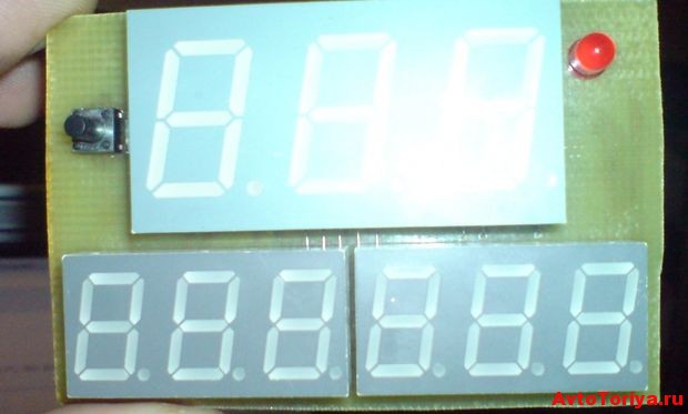
Like this, you should get it in the end:
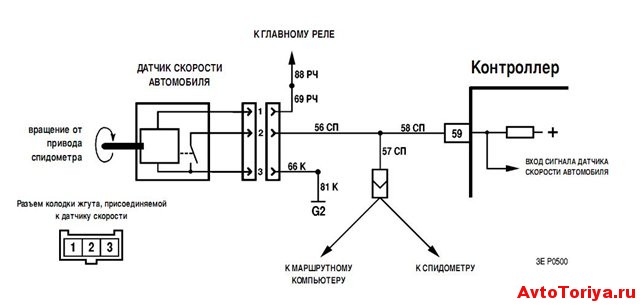
Next, you need to purchase a speed sensor and attach this controller to the car wheel. First, you need to calculate the number of pulses per kilometer run. Measuring the circumference of the wheel will help with this. Those. one revolution will be equal to one pulse on the sensor. The device parameter can now be calculated based on the received data. In extreme cases, you can power on a standard sensor and output the signal from it to our new electronic speedometer, which we assemble with our own hands. Here is a diagram of the device for the VAZ-2110.
The firmware of the microcontroller at the next stage must be carried out by a special compiler. And test your speedometer immediately. And only after making sure that there are no problems, you can connect this device to your car.
At the end, mount the electronic speedometer in the car and in practice check its serviceability and functionality. But if any problems are found in the operation of the device, then it will be necessary to reprogram the microcontroller or change the circuit itself.
And now we are looking at the video of what should happen after you assembled the electronic speedometer with your own hands:
That's all, I think now that the question of how to make an electronic speedometer has remained 100% resolved.
29 January 2015
Each vehicle must have a simple device necessary to control speed mode and safety - speedometer. Read about what a speedometer is, how it works and how it works, as well as about the existing types of speedometers and the peculiarities of their operation, in the article.
Appointment of the speedometer in the vehicle
Modern rules road traffic in some cases, they stipulate the maximum permissible speed with which the car can move in the city, along bridges and highways, along different types roads, etc. Therefore, the driver is faced with the need to control the speed of his car. This task is solved using a special device - a speedometer.
The speedometer is one of the main devices of any vehicle that allows you to measure the current (instantaneous) vehicle speed. Also, all modern speedometers are combined with another device - the odometer, which allows you to measure the car's mileage. Today, the speedometer and odometer are inseparable, so here we will consider both of these devices.
It is interesting to note that the first cars did not have any means of measuring speed, since there was no special need for this - cars of the late 19th - early 20th centuries drove slowly, barely overtaking horse-drawn carriages, and did not create problems. However, over time, the speed of cars grew, and manufacturers began to offer the simplest speedometers as, as they say today, an option. Since 1910, many cars already had speedometers in basic configuration, which was required by the new editions of the national road traffic regulations.
The first mechanical speedometer of modern design was installed in 1923 on several Oldsmobile car models. They were OSA (Otto Schulze Autometer) instruments, and they used principles that are still used today in mechanical speedometers. Only in the 1970s did speedometers of new systems appear - with electronic sensors, with digital indication, etc. However, new devices began to be massively installed on cars only since the 1990s.
Today, the operation of cars without a speedometer or with a faulty speedometer is prohibited in many countries, including Russia. This is indicated by clause 7.4 of the "List of faults and conditions under which operation is prohibited. vehicle»Current traffic rules. Therefore, the condition and performance of the speedometer must be given the most serious attention, and in the event of a breakdown, immediately solve the problem.
Types of modern speedometers
All speedometers can be divided into three large groups:
- Mechanical speedometers;
- Electromechanical speedometers;
- Electronic speedometers.
These speedometers differ in the way they measure speed and display measurement results.
Mechanical speedometers. This is the traditional and simplest solution. In speedometers of this type, both the process of measuring the speed (as well as the distance traveled), and the indication is carried out using mechanical devices... A special gear wheel connected to the secondary shaft of the gearbox acts as a sensor, and as an indicator - a high-speed magnetic induction-type unit with a pointer indicator and a drum counter (odometer). Drum and belt speedometers were previously used, but they fell out of use 30-40 years ago.
Electromechanical speedometers. In such devices, the speed is measured using various electronic or electromechanical sensors connected to the gearbox or directly to the wheel. The speed indication in electromechanical speedometers is carried out using a milliammeter or a modified speed unit of a mechanical speedometer, and the distance traveled is indicated by a counting drum driven by a stepping motor.
Electronic speedometers. This is a further development of electromechanical speedometers, the main difference is the replacement of the odometer - in electronic speedometer it is fully digital (LCD based). Also, speedometers with a digital speed display have gained some distribution, but they are significantly inferior to pointer instruments.
Let's consider the device of each type of speedometers in more detail.
Construction and operation of a mechanical speedometer
A mechanical speedometer consists of the following main parts:
- Gear vehicle speed sensor (DSA);
- Flexible shaft that transmits rotation from the sensor to the speedometer;
- High-speed speedometer unit (actually, the speedometer);
- Speedometer counting unit (odometer).
- magnetic disk
- aluminum hood
- return spring
The speedometer is based on a magneto-inductive speed unit, which consists of a conventional permanent magnet attached to the drive shaft, and a coil, which is just a flat aluminum cylinder. The coil is connected to an axle, at the end of which the speedometer needle is fixed, the axle is held in bearings and connected to a coil spring. The top of the coil is covered with a metal shield, which prevents false readings due to external magnetic fields.
The operation of this high-speed unit is based on the effect of magnetic induction, which generates eddy currents in a non-magnetic material. Everything is very simple here: when a magnet rotates in a coil (aluminum cylinder), eddy currents arise, which interact with the magnetic field of this magnet, and as a result, the coil also begins to rotate, however, due to the spring, it only deflects to one or another angle. This angle depends on the rotation speed of the magnet, that is, the faster the magnet rotates, the more the coil deflects, and the faster the arrow fixed on the coil shows.
The torque is transmitted to the magnet from the DSA through the flexible shaft. The sensor itself is a gear that enters the connection of the gears fixed to the secondary (drive) shaft of the gearbox. Why is the output shaft chosen? Because the speed of rotation of the driving wheels also depends on the speed of its rotation, and hence the speed of the car.
However, the DSA in the box is installed mainly on rear-wheel drive cars, and on cars with front-wheel drive, the sensor is installed on the front left wheel drive.
The odometer is also driven from the drive shaft. For this, a simple gearbox is provided, which rotates the torque from the flexible shaft and transfers it to the odometer counting unit. Usually the gearbox is made on worm gears and has a large ratio - from 600: 1 to 1700: 1 or more.
Mechanical speedometers are simple and reliable in operation, however, they often give large errors, and a flexible shaft also creates some problems, so today electromechanical and electronic speedometers are becoming more common.
Design and operation of an electromechanical speedometer
Electromechanical speedometers are a wide variety of designs and technical solutions. Regardless of the design, all electromechanical speedometers have the same functional units as mechanical ones - a sensor, a speed unit and a counting unit. However, there are several different implementations of these nodes, which means there are many types and varieties of speedometers. Therefore, it is more convenient to classify electromechanical speedometers by the type of sensors and speed nodes used in them.
There are three main types of sensors used in electromechanical speedometers:
- Traditional gear gauges coupled to the gearbox output shaft or left-hand drive front wheel;
- Pulse encoders based on the Hall effect;
- Induction sensors based on the effect of electromagnetic induction;
- Combined sensors (includes a gear sensor connected to the gearbox, and any of the electronic sensors, the signal from which is used to measure the speed of the car).
As for the high-speed nodes, their variety is less:
- Modified high-speed units of the magnetic induction type with indication using a magnetoelectric device (milliammeter) - are used only in tandem with a conventional gear DSA;
- Counting units based on an electronic unit and with indication using a milliammeter - work only in tandem with electronic and combined sensors.
In modified magneto-induction high-speed nodes, the change in the direction of the magnetic field lines from a rotating magnet is measured using a specialized microcircuit or sensor, this signal is amplified and converted electronic unit, and fed to the milliammeter. The amount of current supplied to the device is proportional to the speed of the vehicle, therefore the arrow is deflected to one or another mark of the speedometer.
In high-speed nodes of the second type, the electronic unit converts the signal coming directly from the speed sensor, and the speed is indicated in the same way as described above - using a milliammeter.
It is important to note that electromechanical speedometers use classic drum odometers. They are driven by stepper motors, and the motor is controlled by the same electronic unit that controls the speedometer.
Today, the most widely used are electromechanical speedometers with electronic sensors. They provide more accurate readings, are easy to set up and calibrate (for example, when installing a new speedometer or a speedometer of a different type than was previously installed, it is calibrated using a special scanner without interfering with the mechanical and electronic part), and the signals from the sensors are transmitted by wire, which is more convenient and reliable than the flexible shaft of conventional speedometers. Moreover, in modern cars several speed sensors can be used (usually ABS sensors), which increase the accuracy of speed measurement and the reliability of the speedometer as a whole.
The device and operation of the electronic speedometer
In essence, an electronic speedometer differs from an electromechanical speedometer in that it has a fully electronic odometer with a digital display. The rest of the speedometers are identical. Currently, it is electronic speedometers that are most widespread, they are installed both on cars and on trucks and other equipment.
Such popularity of this type of speedometers can be easily explained by their reliability and greater security. The fact is that every driver can easily "twist" the odometer readings installed in a conventional mechanical or electromechanical speedometer, and it is possible to change the electronic odometer readings only with the help of special equipment. Therefore, today, even in old cars, when installing a tachograph (a device for recording the speed of a car and the distance traveled) or a vehicle control system, it is recommended to install new electronic speedometers, protected from outside interference.
It should be noted that today electronic speedometers with traditional dial gauges are the most widespread, and devices with digital readouts are rare. Why is that? The point is in the peculiarities of our perception: the position of the arrow, even changing, is perceived easier and faster than the digital speed display. We can easily estimate the speed of a car by the arrow, which may fluctuate, but are not able to immediately grasp the speed expressed in two or three constantly changing numbers. Therefore, sensors with arrows are unlikely to ever lose their relevance.
Features of operation of speedometers
Speedometers have one feature - they have a rather high measurement error, while the measurement accuracy depends on a number of factors.
Speedometers with a mechanical drive (with a gear gauge) have the greatest error, and over time, the inaccuracy of the instrument readings increases. This is due to the wear of the sensor gear and to some extent to the wear of the sensor drive gear on the gearbox output shaft. The error can reach 10% or more, and at some point the sensor will stop working normally. Electronic speedometers with pulse or induction sensors do not have this disadvantage, so they have better accuracy.
But no type of speedometer is immune to errors due to various factors. For example, an error of 2.5% or more occurs when wheels with a reduced or increased diameter are installed on a car, as well as when driving on flat tires. The error occurs due to the fact that the speed sensors count the number of revolutions made by the output shaft or the drive shaft of the drive wheel per unit of time. So, with a decrease in the diameter of the wheels (or with too low pressure in the tires), the number of revolutions of the secondary shaft of the gearbox, made per kilometer of the path, will be greater than when driving on wheels with an increased diameter. This means that on small-diameter wheels the speedometer will show an increased speed, and the odometer will count the increased mileage.
An additional error in measuring speed and distance traveled is given by speedometers on front-wheel drive cars. The fact is that the speed of rotation of the front wheel is not the same when different angles turning the angle: when turning to the left, the readings decrease, when turning to the right, they increase (we are talking, recall, about the left front wheel).
However, even on cars equipped with wheels of the recommended diameter, the speedometer can give an error of up to 10%. The maximum error occurs at high speeds (up to 200 km / h or more) - the speedometer overestimates the readings by 10-20 km / h, however, at speeds up to 60-70 km / h, the readings are accurate. This error is deliberately introduced into the speedometers for safety reasons - high readings force the driver to slow down, and in real conditions speedometer readings of more than 120 km / h, in general, are not needed, and in the city the practical limit of readings does lie within 40-60 km / h.
Particular attention should be paid to the choice of a new speedometer, which will be installed on the car in the event of a breakdown of the old one. It is necessary to install those speedometers and sensors that are recommended by the car manufacturer, otherwise the device will give readings with a large error. Modern electronic speedometers in this regard are more versatile - they can be configured (registered in the car's computer) using a special device.
When operating a car, it is necessary to remember these features, and if the speedometer breaks down, repair or replace it as soon as possible. And in this case, the driver will not have problems with the observance of the speed limit and contradictions with applications to traffic rules.
There are several reasons why the driver needs to control the speed of the vehicle. The main one is speed limits on public roads. Because permissible speed movement on certain roads is different, then you have to check the speedometer all the time. There is one more nuance. The speedometer kit includes a counting unit that shows the distance traveled by the car for all the time. It is called an odometer. Thanks to him, you can accurately determine the onset of the moment when you need to change, for example, filters or oil. Mileage information is also not the last factor when buying a used car. In addition, the odometer can show intermediate data on the kilometers traveled. On vehicles that are not equipped on-board computer, such an odometer function is convenient for calculating fuel consumption, or in order to measure the distance, say, from work to home. The artist and inventor Leonardo to Vinci in 1500 created a sketch of an instrument that could determine the speed of the carriage. But it took about three hundred years before such a mechanism was used to measure the speed of steam locomotives, while the invention of the car speedometer is credited to the engineer Otto Schultz. The appearance of the device dates back to 1902. It is believed that the first car companywhich began to install speedometers on was Oldsmobile. Like any other at least somewhat complex new device, the speedometer was expensive and was not included in the standard package. However, soon the availability of the speedometer became a prerequisite vehicle operation. Most car models were equipped with two speedometers at once: small and large. The second was needed so that a police officer could see the speed of a passing car on it. The principle of operation of speedometers has remained almost unchanged for a hundred years. During this time, only the mechanism of the indicator itself has changed. So, at one time, belt speedometers were popular. Instead of the arrow familiar today, a ribbon moved in a horizontal window with divisions. These speedometers were especially popular in America and Japan in the 60s and 70s. Devices of this type could be found on soviet cars, for example, on Gas 24. There were also so-called drum speedometers. They were on many pre-war cars of various companies. The speed was reflected in them thanks to a spinning drum with engraved numbers. All this is about mechanical speedometers, digital ones appeared relatively recently - in 1993.Device and principle of operation1
There are two types of speedometers: mechanical and electronic. If the former are equipped with a mechanical indicator, such as an arrow, then the latter may instead have an electronic indicator - the numbers on the display. Let us dwell separately on the device and the principles of operation of each type.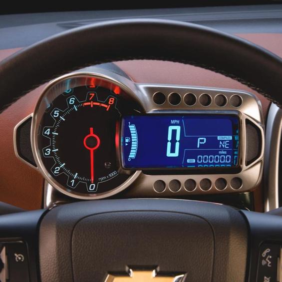 The most popular type of mechanical speedometer is magnetic induction. It includes two mechanisms: high-speed and counting. The first consists of a cable (flexible shaft), magnetic disc, coil and spring. The cable is connected to a sensor located on the gearbox shaft. The sensor converts the movement of the shaft into rotation of the cable. Rotating, the cable spins the magnetic disk. On top of the disc is a rotating reel with an axis. The movement of the disc creates a magnetic flux, which in turn excites currents in the coil. In connection with this effect, the coil also starts spinning after the disc. The spring limits its rotation to an angle that depends on the speed of rotation of the disk. The spring has a certain set stiffness, which determines the accuracy of the speedometer. The speedometer arrow is fixed at the end of the axis rotating together with the coil.
  The speedometer counting unit also has a cable drive. The counter itself consists of several drums that are connected in series gear transmission... Thanks to this, for ten turns of the first reel, there is one turn of the next one, and so on. Typically, the counter uses five reels. Thus, its maximum indicator will be equal to 99,999. Upon reaching this figure, the counter is reset to zero. The electronic speedometer does not differ from the mechanical one. But in contrast to it, the speed sensor in the electronic speedometer no longer turns the flexible shaft, but transmits electrical impulses, obeying which the arrow of the device turns. The movement of the arrow depends on the number of pulses received per unit of time. The odometer in this case is arranged in the same way, except that the drums are driven by a small electric motor.