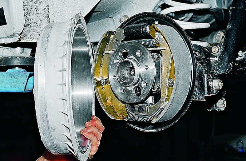
The drum brake mechanism is functionally designed to change speed mode vehicle. In addition, a drum brake mounted on the rear wheelset provides the function parking brake.
The main structural element brake mechanism of this type, in fact, which gave it such a name, is a drum, or a metal bowl, fixed on the wheel hub.
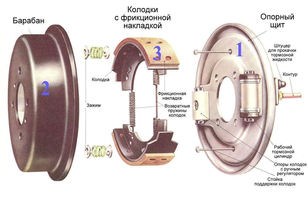
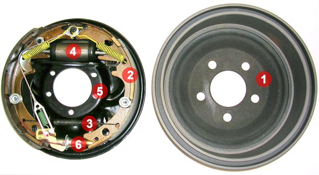
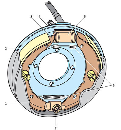
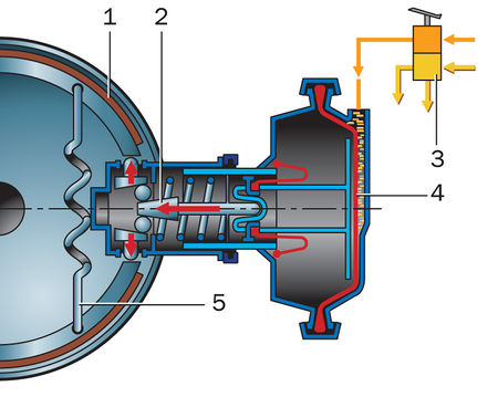
The drum brake (Fig. 1) consists of the following main parts:
The brake drum, the material for the manufacture of which is high strength cast iron. The inner surface of the drum, which is in direct contact with the rest of the mechanism, is carefully polished. It is mounted on a support shaft (in this case, a bearing is pressed into the drum) or a wheel hub.
Brake pads (item 4). They are made of metal and have a crescent shape. The working surface of the brake pad is equipped with a friction lining (based on asbestos).
Brake hydraulic cylinder (item 2). This is a hollow cast iron cylinder with two working pistons, filled with working (brake) fluid. The cylinder is equipped with a bleed valve to remove air from the brake system. To prevent leakage brake fluid use sealing cuffs.
Upper (item 1) and lower (item 5) compression springs operating in "compression". Their main working function is to prevent the brake pads from coming apart in the "rest" mode.
Protective disc mounted directly on the hub (rear beam).
Spacer bar (item 3), which is a metal plate of a specific configuration (with special cutouts). Functional purpose of this element consists in the installation of a self-feed mechanism. Also, when installing braking device on the rear wheelset, the spacer bar actuates the second brake pad while allowing the parking brake to function. It is used in drum brakes with one brake cylinder.
Self-drive mechanism (in the form of two eccentrics located in the protective disc housing), which ensures the expansion of brake pads with worn friction linings.
Drum brakes - how they work
The principle of operation of a drum brake is as follows:
After the driver has pressed the brake pedal in the circuit brake system pressure arises.
Under the influence of the pressure of the brake fluid, the pistons of the brake cylinders, overcoming the resistance of the clamping springs, initiate the divergence of the brake pads.
Brake pads, diverging and tightly fitting the friction linings to the working surfaces of the brake drums, they reduce the speed of their rotation, thereby slowing down the rotation of the vehicle wheels.
Braking efficiency brakes drum type is slightly lower than the same indicator disc brakes... So, the difference in magnitude braking distance may differ significantly (up to 20%). And there are several, quite objective reasons for this:
Readers know that currently the most common in automotive industry received two types of brakes - disc and drum. If everything is clear with disc brakes, then the structure, principle of operation and efficiency of operation of drum brakes for many still remain a mystery. In today's article we will talk about the main components of drum brakes, describe the algorithm for their operation, and also find out the main advantages and disadvantages of their use.
What are drum brakes made of?
The device of drum brakes is much more complicated than the design of their disc "brothers". The main internal parts of such brakes are:
- Brake drum. Element made from high-strength cast iron alloys. It is mounted on the hub or support shaft and serves not only as the main contact part, interacting directly with the pads, but also as a housing in which all other parts are mounted. The inside of the brake drum is sanded for maximum braking performance.
- Pads. Unlike disc brake pads, pads used in drum mechanisms have a semicircular shape. Their outer part has a special asbestos coating. If the brake pads are installed on a pair of rear wheels, then one of them is also connected to the parking brake lever.
- Tension springs. These elements are attached to the upper and lower parts of the pads, preventing them from diverging in different directions at idle.
- Brake cylinders. This is a special body made of cast iron, on both sides of which working pistons are mounted. They are activated by the hydraulic pressure that occurs after the driver has pressed the brake pedal. Additional parts of the pistons are rubber seals and a valve for removing air trapped in the circuit.
- Protective disc. The part is a hub-mounted element to which the brake cylinders and pads are attached. They are secured by using special clamps.
- Self-feed mechanism. The mechanism is based on a special wedge that deepens as the brake pads are grinded. Its purpose is to ensure a constant pressure, pads to the drum surface, regardless of the wear of their working surfaces.
Drum brake device
The components we have listed are common. Most of them use them largest manufacturers... There are a number of parts that are installed privately by some companies. Such, for example, are the mechanism for bringing the pads, all kinds of spacers, etc. It makes no sense to dwell on them in detail.
How drum brakes work
The main sequence of functioning of the drum mechanisms is approximately as follows. The driver, if necessary, presses the pedal, creating an increased pressure in the brake circuit. presses on the master cylinder pistons, which activate the brake pads. They "diverge" to the sides, stretching the tension springs, and reach the points of interaction with the working surface of the drum. Due to the friction that occurs during this, the speed of rotation of the wheels is reduced, and the car slows down. The general algorithm for the operation of drum brakes looks like this. There are no significant differences between systems with one piston and two.
Advantages and disadvantages of drum brakes
Despite the seemingly general obsolescence of the design, many automakers still use drum brakes on their models. The point is the presence of many advantages that have a beneficial effect on the use of the car.
- First of all, drum brakes last 2-3 times longer than disc brakes. This applies not only to the pads, but also to the brake discsthat wear out no less.
- Secondly, drum mechanisms are not afraid of water ingress, while very hot surfaces of disc brakes with sharp cooling with water can become covered with microcracks, which leads to their early failure.
- Thirdly, it is much easier to install a parking brake in a drum brake system than to integrate it into disc systems. Of course, simplicity significantly reduces the cost of manufacturing the overall structure.
The main disadvantage of drum brakes is their lower efficiency in comparison with disc mechanisms. It is unsafe to use them on cars with powerful revving motors installed under the hood, as well as on models with a high mass.
Conclusion
Summing up, let's say that in the near future, drum brakes, of course, "give way" to more advanced disc systems. Already, many manufacturers install drum brakes exclusively on budget models, assembling the vast majority of their new products with various variations of disc systems.
Drum brakes and their elements
TO Category:
Car brake control
Drum brakes and their elements
The drum brake mechanism has symmetrical shoes (usually two), carrying friction brake linings on the outer cylindrical surfaces, which, under the action of the drive device, are pressed against the inner cylindrical surface of the drum. Diagrams of the most common drum brakes are shown in Fig. 34. They are classified by the type and number of driving devices, as well as by the number of degrees of freedom of the pads. The block has one degree of freedom if it rotates around a fixed geometric axis. This is achieved either by pivoting the shoe with an axle fixed in the caliper, or by placing the radius end of the shoe in the corresponding cylindrical seat of the caliper.
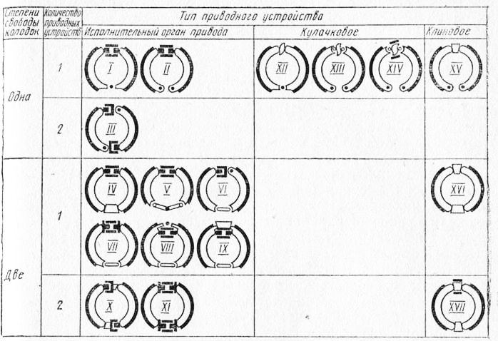
Figure: 34. Diagrams of drum brakes s
For pads with two degrees of freedom, the geometric axis of their rotation has the ability to move, which allows the pads to self-align, and therefore, provides a better fit to the drum and more uniform wear of the lining. Pads with two degrees of freedom either rest with a rounded end on the beveled plane of the caliper and slide along it, or are connected to the latter using an intermediate link, which, in turn, has a fixed geometric axis of rotation relative to the caliper. Sometimes this link is the second brake pad.
The efficiency of different drum brakes with the same dimensions and equal driving forces is very different. The most effective is the brake mechanism, which has one clamping and second servo shoes with sliding bearings and one drive device in the form of a double-sided wheel cylinder. With this type of brake, the servo action reaches its highest value. However, the higher the efficiency of the braking mechanism, the more sensitive it is to changes in the coefficient of friction of the friction pair. Since the coefficient of friction is a variable value and depends on many factors (speed and temperature in the friction zone, the magnitude of the driving force, the stiffness of the brake parts, etc.). the most effective brakes are usually the most unstable. During their operation, vibrations, squeaks, etc. occur more often. In this regard, the area of \u200b\u200buse of such braking mechanisms is gradually narrowing.
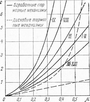
Figure: 36. Static characteristics of brakes
In recent years, with the proliferation of automated braking systems that allow for increased driving force, brakes with low servo action are increasingly being used. It should be noted that pads with two degrees of freedom have more servo action than pads with one. However, such pads, especially those with sliding bearings, are very prone to vibrations and squeaks. In addition, the angle of the pad support must be such that the pad returns to its original position after braking.
One of the simplest is a drum brake with articulated shoe supports and a cam drive device. Its construction is shown in Fig. 37. The shoes of such a brake have equal displacements, determined by the shape of the expander (mechanisms of this type are sometimes called brakes with equal displacements). As a result, the braking moments created by both pads are equal, and the driving force acting on the squeezing block is much greater than that acting on the pressing block. The total braking torque of this brake when the brake drum rotates in both directions is practically the same; the wear of both linings is almost the same. The advantages of such a brake mechanism include its high stability, as well as the fact that the forces applied to the brake drum from the side of the pads are practically balanced and do not create additional load on the wheel bearings. The disadvantages of equal displacement brakes are the need for a significant drive force and the relatively low efficiency of the cam drive. According to domestic researchers, the efficiency of the cam drive device ranges from 0.60 to 0.80. To reduce friction between the fist and the block, a roller is installed, and plain bearings are used in the fist supports, which increases the efficiency of the drive device to 0.75-0.90. In practice, due to the ingress of dirt into the cam bearings and in the axles on which the rollers rotate, the efficiency of the cam drive device is at the lower limit. It should also be noted the increased labor intensity maintenance such a brake mechanism due to the need to periodically lubricate the cam supports.
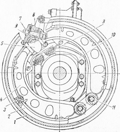
Figure: 37. Brake mechanism of the ZIL-130 car:
1 - brake bp slave; 2 - friction lining; 3 - rivet; 4 - tormpvalue kolodchp; 5 - expanding fist; 6 - an adjusting lever; 7 - cash worm; 8 - worm; 9 - return spring of the pads; 10 - support; 11 - pads axis
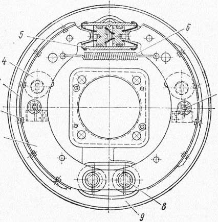
Figure: 38. Brake mechanism of the car GAZ-21:
1 - brake shoe; 2- rivet; 3 - friction pad; 4 - eccentric adjusting washer; 5 - wheel cylinder; b - pull-back spring; 7 - pad retainer; 8 - the axis of the shoe; 9 - support
The brake mechanism, which is shown in diagram II in fig. 34. It has pivot pads and a drive device in the form of a double-sided wheel brake cylinder (Fig. 38). Here, equal driving forces are applied to the pads, but the braking torque generated by the presser is greater than the release. Accordingly, the wear of the pressure pad lining is also greater. This brake mechanism is equally effective when the drum rotates in both directions. With an equal driving force, it gives a higher braking torque than the cam brake described above, due to greater servo action and higher (up to 0.95-0.98) efficiency of the drive device.
The disadvantage of this braking mechanism is the presence of an external force loading the wheel bearings, as well as the unequal durability of the friction linings.
To eliminate these disadvantages, stepped wheel cylinders are used, which create different driving forces. Sometimes the pad on the squeeze block is made smaller or thinner than on the presser.
The design of the third rather common brake mechanism is shown in Fig. 39. This is a brake mechanism with sliding shoe supports and two drive devices in the form of one-way wheel cylinders. Both pads are pressure pads when the brake drum rotates forward and release pads when it rotates backward, as a result of which the effectiveness of the braking mechanism when the car is moving in reverse significantly less.
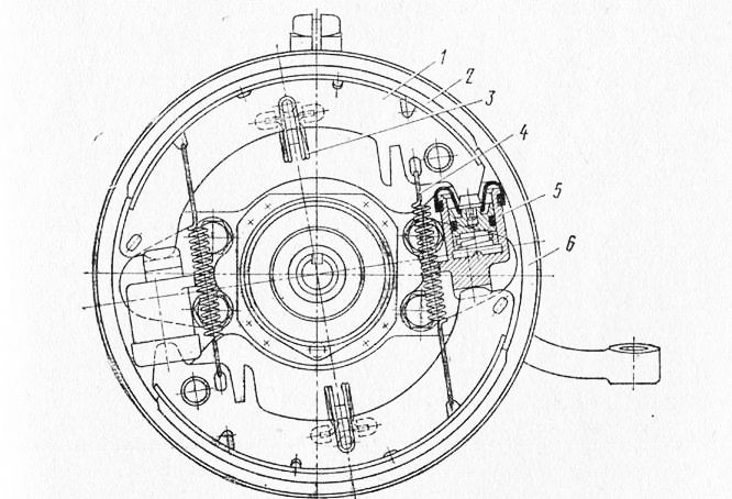
Figure: 39. Brake mechanism of the car "Moskvich-408":
1 - brake shoe; 2 - friction lining; 3 - clamping spring; 4 - pull-back spring; 5 - wheel cylinder; 6 - support
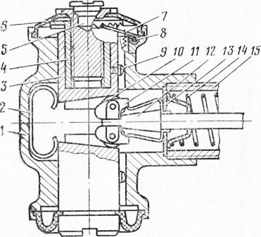
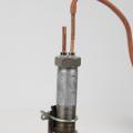
Figure: 40. Wedge drive device of the drum brake mechanism:
1 - case; 2 - returnable spring of rollers; 3 - plunger; 4 - plunger head; 5 - pin; 6 - dustproof cover; 7 - dog; 8- spring of the dog; 9 - retainer; 10 - roller; 11 - roller holder; 12 - stock; 13 - sealant; 14 - rod return spring; 15 - brake chamber housing
This is a significant drawback of such a brake. In addition, the use of two spaced drive devices makes it difficult to drive the parking brake system. However, the equality of the moments of the pads, uniformity of wear and high servo-action make it possible to successfully use a mechanism of this type on the front wheels passenger cars.
In recent years, a new design of drum brakes for pneumatic braking systems has been developed. In it, the pads are unclenched not by a traditional fist, but by a wedge drive device (Fig. 40). Since the wedge stem is floating, such a brake has a higher efficiency than the above-described cam-operated brake. The pad support is both sliding and articulated. A very promising design is a brake mechanism with two wedge drive devices, one of which has a conventional brake chamber, and the other has a chamber with a spring brake. The advantages of a brake mechanism with a wedge drive are more uniform and less wear of the parts of the rubbing pair, higher efficiency, smaller dimension of the brake chambers, as a result of which significantly less compressed air... However, the wedge drive device also has disadvantages: increased manufacturing cost and the need for good dirt protection.
The most important elements of the brake mechanism are the parts that make up its friction pair - the brake drum and friction linings. Brake performance and its retention under various conditions depend almost entirely on the quality of these parts.
The specificity of the brake drum operation is that due to the extremely low thermal conductivity of the friction lining material, more than 95% of the heat released during braking is absorbed by the drum itself. Tests have shown that the temperature of the brake drums of heavy vehicles on long slopes can reach 250 - 360 ° C. Thermal stresses arising from such temperatures in the drum are aggravated by the action of cyclic loads from the pads. Note also that for safety reasons, the strength of the brake drum must be guaranteed. Brake drums trucks and buses are usually made of cast iron and often have ribs on the outer surface to increase strength, rigidity and heat transfer. On passenger cars, to reduce weight, a combined drum is used - a stamped steel or aluminum cast disc, cast into a cast iron rim.
The use of cast iron for the manufacture of brake drums is due to the fact that this material, together with modern friction linings, provides a high coefficient of friction, works well for compression, and has sufficient thermal conductivity. Less demanding transmission brake drums are sometimes made of stamped steel.
The friction lining is made of a complex asbestos composition, which consists of a filler - asbestos fibers and a binder - synthetic resins or their mixture with various organic substances. Sometimes zinc or brass particles are added to the composition, which increase the mechanical strength of the lining and improve its thermal conductivity, but they intensify the drum wear.
Currently, asbestos-friction brake linings are mainly manufactured using the combustion molding process. In recent years, experiments have been carried out on the use of cermet and metal-resin (semi-metallic) linings. However, such linings are still used only in braking mechanisms of special vehicle... Possessing high heat resistance, they have insufficient efficiency in the cold state, cause increased drum wear, create vibrations and squeak of brakes.
Automotive brake friction linings must have the following properties:
- high coefficient of friction, stable when changing sliding speed, specific pressure and temperature in the entire range of real operating conditions;
- high wear resistance; low moisture and oil absorption, the ability to quickly restore efficiency after getting wet;
- durability and reliability, the ability to work without cracks, tears and drum material deposition on the surface of the lining, without scoring and excessive wear of the drum material;
- lack of tendency to vibrations and "squeak". The method of attaching the friction linings to the pads is of great importance. High-rigidity truck linings are usually riveted or screwed on. This method of fastening is convenient for repairs, but it reduces the working area of \u200b\u200bthe pad and its durability, since the working thickness decreases. Thinner and therefore flexible passenger car linings are often glued. The glued pad works almost to complete wear, but its removal and replacement is very laborious.
During operation, the friction linings and the drum wear out, which entails an increase in the gap between them in the unbraked state. An increased clearance leads to a delay in the operation of the brake, an increase in the strokes of the actuating elements of the drive, and, consequently, to an overrun of the working fluid in it. For hydrostatic brake drives, this can lead to failure.
To avoid such phenomena, modern braking mechanisms are equipped with devices for manual or automatic adjustment of the gap in the friction pair. The principle of operation of these devices is to periodically change the position of the unbraked shoe. There are two types of adjustments: factory, which is made after assembling a new brake or after replacing its parts, and operational, which eliminates the effect of wear. For operational adjustments of brakes with hydraulic cylinders, washers with a spiral or eccentric profile installed on the brake caliper are used. Turning such a washer 4 (Fig. 38) causes a corresponding angular movement of the shoe resting on it. For brakes with a cam drive, a worm pair in the adjusting lever serves for this purpose (Fig. 37). Turning the worm shaft brings the lever, and therefore the expander 5, to a new angular position, and the pads approach the drum. In wedge brakes, this is achieved by increasing the length of the plunger by rotating the plunger head (fig. 40).
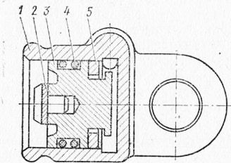
Figure: 41. Automatic regulator of a gap of the car GAZ-24:
In the factory setting, in addition to these devices, the pad supports are also used. So, in the braking mechanisms shown in fig. 37 and 38, the axes of the shoes are made in the form of eccentrics and their rotation changes the position of the shoes.
In recent years, automatic devices for adjusting the clearance in the brake mechanism have become widespread. Such devices significantly reduce the labor intensity of maintenance of the brake system and increase traffic safety, constantly maintaining the brakes in a state of technical readiness.
The principle of operation of automatic regulators is based on limiting the reverse stroke of the brake pads when releasing the brake, if their working stroke due to the increased clearance is greater than the specified value. Automatic regulators are built into the drive device or mounted directly on the block. Examples of their designs are shown in Fig. 41-13.
The piston backstroke limiter built into the wheel brake cylinder (Fig. 41) is a split spring ring that is loosely worn on the piston neck and inserted into the cylinder with a large interference (the force required to move it in the cylinder is 60 kgf). The width of the piston neck is greater than the width of the ring, as a result of which the axial movement of the piston relative to the ring is ensured by a predetermined amount (from 1.2 to 2.1 mm). If the clearance in the brake is greater than the specified value, then the piston, when braking at the end of its stroke, will move the ring to a new position (the pressure force in the drive is sufficient for this). When released, the brake spring of the pads will not be able to overcome the ring tension, and the piston, together with the pad, will be installed closer to the drum.
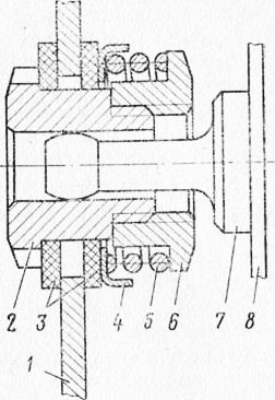
Figure: 42. Automatic backlash adjuster BA3-2103:
1 - brake shoe; 2 - yatulka; 3 - friction washer; 4 - support spring cup; 5- spring; 5 - nut; 7 - axis; 8 - brake caliper
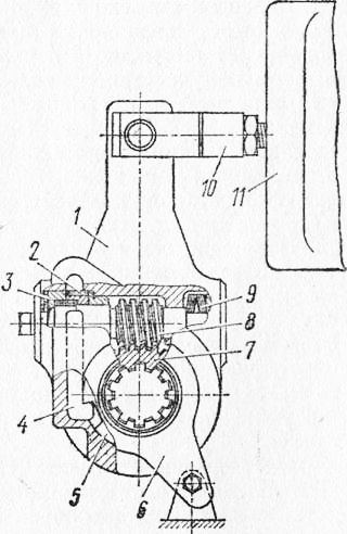
Figure: 43. Automatic adjusting lever of the cam drive device
The autonomous pad backstop shown in fig. 42, consists of friction washers that compress the edge of the brake shoe under the action of a powerful spring, as well as inserted with a large gap into the hole of the edge of the shoe of the threaded bushing and the axle, which is welded to the brake caliper. The return stroke of the pad is limited by friction between its rib and the washers.
The design of the automatic adjusting lever of the cam drive device is shown in fig. 43. When braking, the body of the adjusting lever turns counterclockwise and the toothed rack, resting its teeth against the cutout of the disk connected to the fixed lever, turns the gear and the outer conical coupling half. In this case, under the action of the force on the brake chamber rod, the Belleville springs are compressed and the outer conical coupling half does not touch the inner one, made in one piece with the worm. When braking, the gear rack is held in a new position, as a result of which the worm, the conical coupling half of which is connected to the outer conical coupling half under the action of springs, rotates through a small angle. The worm wheel, which is put on the splines of the expander fist, also turns in engagement with it. Thus, the fist turns and the gap between the pad and the drum is reduced. This process occurs with every braking. The amount by which the gap is reduced depends on its original value. So, with an initial clearance between the pad and the drum of 1.6 mm for 40 brakes, the clearance decreases by 1.1 mm, and with an initial clearance of 0.5 mm - only 0.1 mm.
The automatic gap adjuster of the wedge drive works in a similar way, in which, with a large plunger stroke, the pawl jumps to the next tooth and, during the return stroke, rotates the plunger head, as a result of which the pin extends and brings the shoe closer to the drum.
TO Category: - Vehicle brake control
Shoe drum brakes:
and - mechanism with one-sided supports;
b - with spaced supports;
in - self-reinforcing mechanism;
r - mechanism with an expanding fist
Shoe drum brakes, despite their external similarity, differ significantly from each other in design and properties. The figure shows the main schemes of drum shoe brakes. Basically, they differ in the location of the pad supports and the nature of the driving forces that push the pads apart and press them against the drum from the inside. The difference in construction also predetermines the difference in properties.
Drum mechanism with equal driving forces and one-sided arrangement of pad supports:
1 - brake drum;
2 - friction lining;
3 - block;
4 - brake shield;
5 - brake cylinder;
6 - returnable (tightening) springs;
7 - eccentric brake adjustment
The illustration shows a drum brake with equal driving forces and one-sided shoe supports.
The platter is fixed to the bridge beam. In the lower part of the support disk, two pins are installed, on which eccentric washers are fixed. The position of the fingers is fixed with nuts. The eccentric washers are fitted with the lower ends of the pads. The adjusting eccentrics are fastened to the support disc by bolts, which are kept from free rotation by pre-compressed springs. A compression spring presses each shoe against its adjusting eccentric. The spring fixes the adjusting eccentric in any position when turning it behind the bolt head. Thus, each pad is centered relative to the brake drum by adjusting eccentrics and eccentric washers of the fingers. The upper ends of the pads are in contact with the pistons of the working cylinder. The pads are held against lateral displacements by guide brackets with leaf springs.
The length of the friction pads attached to the front and rear pads is not the same. The front pad is longer than the rear. This is done to ensure uniform wear of the pads, since the front pad works longer as a primary pad and creates more braking torque than the rear pad. The brake drum is attached to the wheel hub. The drum is removable for easy access to the pads.
When braking, the fluid pressure in the wheel cylinder pushes the pistons in the opposite direction, they act on the upper ends of the pads, which overcome the spring force and are pressed against the drum. When the brake is released, the pressure in the cylinder decreases and thanks to the return spring, the pads are brought back to their original position.
The mechanism has a special drive lever connected by its upper end to one brake shoe, and through a bar - to the other. A parking cable is attached to the lower end of the arm. When pulling out the cable, the lever turns and presses against the drum first one block, and then another across the bar.
Brake car with spaced supports made according to the scheme (see Fig. b). It has two identical brake pads, each mounted on a matching pivot pin. The pads are pulled together by springs. The ends of the pads are in contact with the pistons of the wheel cylinders. The working cylinders are connected to the main brake cylinder and between themselves by the pipeline. The mechanism has automatic device clearance adjustment.
Platter disc servo brakes (see fig. c) mounted on the gearbox; it has two pads, expanding and adjusting mechanisms. The upper ends of the pads are pressed by the tension springs against the push rods of the release mechanism, and the lower ends are pressed against the supports of the adjustment mechanism. The force of the clamping springs of the left shoe is less than the force of the springs of the right shoe. The cracker of the adjusting mechanism can move with the pad supports by 3 mm relative to the screw. In the released position, the cracker is pressed against the body by strong springs and the specified gap is set from the side of the left block. When the brake lever is moved, the force from it is transmitted through the rod to the two-armed lever. The position of the brake lever in the braked state is fixed with a latch on the toothed sector. At the same time, the short shoulder of the two-armed lever presses on the expanding rod, which, sliding into the body, spreads the pushers of both pads with balls. The left block is pressed first to the drum, which has weaker clamping springs. If braking occurs when the car is moving forward, then this block is captured by the drum and its lower end moves the right block until it touches the drum (the block moves, which does not exceed 3 mm, counterclockwise). Both pads act as primary pads, with the drive force for the right pad being the frictional force transmitted from the left pad. As the braking torque of the transmission parking brake increases main gear, then its dimensions are smaller than the dimensions of the wheel brakes or brakes installed after the interwheel differential.
Equal pad brake (see fig.d). The pads are supported on axles with eccentric necks. The axles are installed and secured with nuts in brackets riveted to the platter. When installing the brake, the axis is rotated and thereby the end of the shoe is displaced relative to the drum. The compression spring presses the pads against the expander. Two friction pads are riveted to the pads. The brake drum is cast from cast iron and attached to the wheel hub with studs. The expander is made in one piece with the shaft and is installed in the bracket. A lever is attached to the spline end of the shaft. A worm gear is placed in the lever, which serves to adjust the clearance in the brake mechanism.
When released, there is a gap between the shoes and the drum. During braking, the air pressure is perceived by the membrane of the brake chamber mounted on the bracket, and its rod turns the shaft with the expander fist behind the lever. The pads are pressed against the drum, causing the wheel to brake. The expander profile is made so as to ensure that the ends of the shoes move at equal distances. This achieves a balanced braking mechanism, equal braking torques and pad wear.
Braking mechanism with wedge-shaped expansion device and automatic clearance adjustment:
1 - block;
2 - expanding wedge;
3 - brake valve;
4 - brake chamber;
5 - spring
On a number of cars, brakes with a wedge expanding device and an automatic gap adjustment are used. A support is fixed on the supporting disk, into the cylindrical holes of which two pushers are inserted. Adjusting sleeves are located inside each pusher. On the outer surface of each adjusting sleeve, there is a spiral thread with a triangular profile of the teeth, and on the inner surface there is a thread into which the adjusting screw is screwed. During the initial adjustment of the brakes, by turning the adjusting screws, the gap between the brake drum and the shoes is set, the value of which is then automatically maintained. The ratchets are pressed against the adjusting sleeves, which have teeth that mesh with the outer teeth of the adjusting sleeves.
The expanding device consists of a wedge, two rollers (the axes of which are located in a separator), a thrust washer and a dust cap. When braking, a force is transmitted to the wedge from the brake chamber rod, as a result of which it moves in the axial direction and, by means of rollers, pushes the pushers apart. The adjusting bushings and screws moving at the same time press the pads against the drum, and the ratchet pawl jumps over the teeth of the adjusting bushings. When release occurs and the tappets with their associated parts move in the opposite direction, the adjusting sleeves rotate due to the force generated in the engagement between the ratchet pawls and the sleeves, as a result of which the screws are turned out. The necessary clearances are established between the pads and the drum. As the gap between the pads and the drum increases, the ratchet pawls engage with another pair of teeth of the adjusting sleeve, which automatically restores the gap in the brake mechanism.
Brake drums for wheel and transmission brakes are usually cast in gray iron. In some brakes, the drum disc is stamped from sheet steel and connected to a cast iron drum when cast into a one-piece structure. The brake drums of passenger cars are made of an aluminum alloy with a cast iron ring cast inside. Ribs are sometimes made on the drums to increase the rigidity of the structure and improve heat dissipation. Drum brake pads have a T-shape for cross-section rigidity. Sometimes the block rests loosely with its lower end on the platform and is not fixed. Such a block is self-aligning relative to the drum when braking.
Friction linings are made of materials with a high coefficient of friction (up to 0.4), high heat resistance and good wear resistance. Previously, hot pads were formed mainly from fibrous asbestos mixed with organic binders (resins, rubber, oils). Now the use of asbestos in brake linings is prohibited by law, since asbestos is recognized as a carcinogenic material.
Drum brake arrangement
Drum brakes work on the same principle as disc brakes: The brake pad presses against the rotating surface. Only in this design is this surface called a drum.
Most vehicles have drum brakes set to rear wheels, and disc - on the front. Drum brakes are designed with more parts than disc brakes and are therefore more difficult to maintain. However, they are cheaper to manufacture and easier to integrate with a handbrake.
In this article, we will talk about how drum brakes work, how to maintain them and consider the installation of the mechanism. hand brake.
Let's start with the basics.
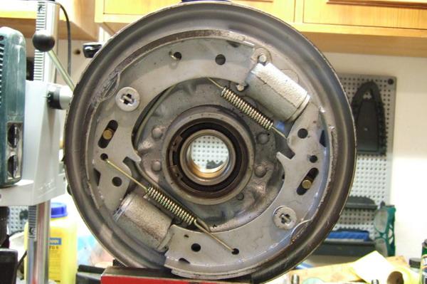
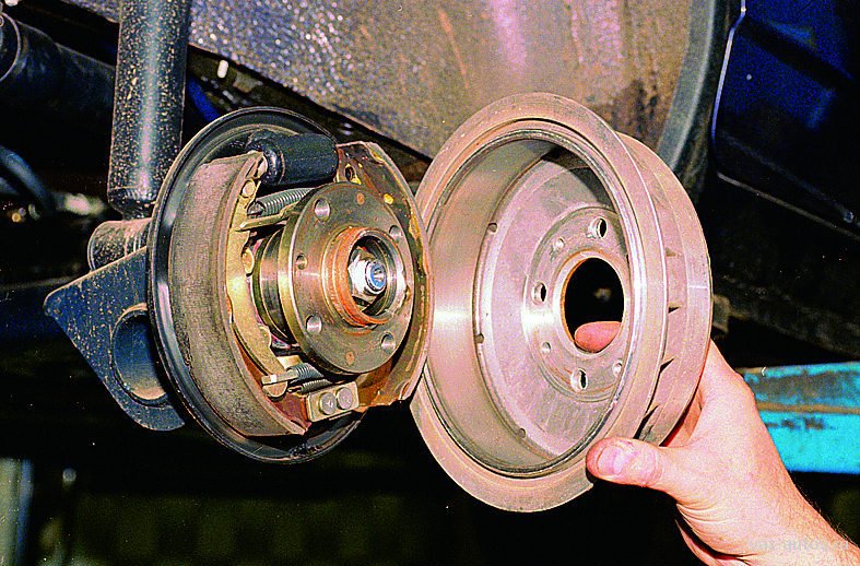 Drum brake with removed drum
Drum brake
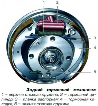 Drum brake components
A drum brake looks like a complex design, but it's much simpler when you look at it in more detail. We offer to disassemble the brake and see how it works.
Like a disc brake, a drum brake has two pads and a piston. But the drum brake also has a brake adjuster, a handbrake mechanism, and many springs.
When you press the brake pedal, the piston presses the pads against the drum. Simple enough, but what are all these springs for?
In fact, the situation is a little more complicated. Many drum brakes are self-acting. The brake pads are in contact with the drum, and a kind of wedging action occurs, as a result of which the pads are pressed more against the drum.
The additional braking force that this wedge provides allows for a smaller piston size than disc brakes. However, due to seizure, the brake pads must move away from the drum after the end of braking. For this, springs are used. Other springs hold the pads in position and return the brake regulator to its place after it has applied.
Brake regulator
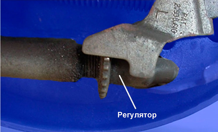 Brake regulator mechanism
For the drum brake to work properly, the pads must be close to the drum, but not in contact with it. If they are pushed too far (for example, when the pads are worn), the piston will need more fluid to cover this distance, and the brake pedal will "go to the floor" when pressed. For this reason, most drum brakes use an automatic adjuster.
Let's look at the structure of the regulator mechanism. The regulator is also self-acting.
As the pad wears out, more space forms between the pad and the drum. At each stop of the car, the pads are pressed against the drum as much as possible. As the gap increases, the adjuster lever moves the gear by one tooth. The regulator, like the bolt, is threaded. When turning, it unscrews, reducing the gap. With further pad wear, the regulator is still unscrewed, providing a close position of the pads relative to the drum.
In some vehicles, the regulator is activated when the hand brake is applied. But the adjustment of such a mechanism can get lost with prolonged non-use of the hand brake. With such a system, apply the handbrake to the vehicle at least once a week.
Hand brake
The hand brake, in addition to the main brake system, can be activated by other means. The drum brake design allows a simple cable drive mechanism to be used.When using the handbrake, the cable pulls on the lever that presses the pads.
Service
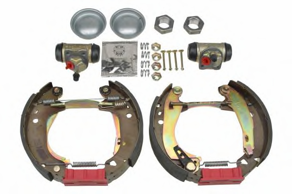
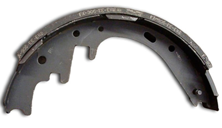 Brake shoe
For the most part, drum brake maintenance consists of replacing brake pads. Some drum brakes have a service port on the side to check for pad wear. The brake pads must be replaced when the thickness of the friction material on the rivets is 0.8 mm. If friction material is applied to the backing plate (without rivets), then the pads must be changed when the thickness of the friction material is 1.6 mm.
As with disc brakes, worn pads can leave grooves on the drums. With prolonged use of worn out pads, rivets can damage the drum. Drums with deep grooves can be reground. If for disc brakes the minimum permissible thickness looks, then for drum brakes - the maximum permissible diameter. The contact surface in drum brakes is located inside the drum. When material is removed, the diameter increases.