The task of the steering gear is to change the direction of movement of the vehicle. In most cars, you can only change the direction of the front wheels, but there are modern models, which are controlled by changing the direction of all four wheels.
The steering system of a passenger car consists of a steering device and a drive. As a result of the rotation of the steering wheel, the engine begins to move forward. Then the steered wheels turn and the car changes direction.
During this process, the initial movement of the driver is amplified several times. The steering gear diagram shows which parts and mechanisms are involved in the process of driving a car. On modern cars and trucks designed to transport large loads, hydraulic boosters are additionally installed. The hydraulic boosters make driving easier and increase driving safety.
a) the traditional scheme; b) rack and pinion steering;
1 - lever steering knuckleand; 2 - lateral steering rod; 3 - pendulum arm; 4 - transverse steering rod or gear rack; five - steering wheel; 6 - steering shaft; 7 - steering gear housing; 8 - steering bipod.
Figure 3.7 - Steering diagram
Worm-type steering gear

Figure 3.8 - Worm type steering gear
This is the oldest type of steering. The system consists of a crankcase with a built-in screw called "worm". The "worm" is directly connected to the steering shaft. In addition to the screw, the system has one more shaft with a roller sector. The rotation of the steering wheel leads to the rotation of the "worm" and the subsequent rotation of the roller sector. A steering arm is attached to the sector roller, connected by means of a hinged control with a linkage system.
As a result of the operation of this linkage system, the steered wheels turn and the vehicle changes direction. The worm-type steering mechanism has several disadvantages. First is big loss energy due to high friction inside the mechanism.
Secondly, there is no rigid connection between the wheels and the steering wheel. Thirdly, in order to change the direction of movement, you need to turn the steering wheel several times, which not only looks out of date, but also does not meet the existing management standards in the world.
Steering gear with three-ridge roller and globoid worm
The steering gear can be worm, screw, crank, gear transmission or a combination of such transmissions. Greater distribution among passenger cars received steering mechanisms in the form of a worm gear with a globoid worm and gears - racks (rack type). Let's consider these steering mechanisms in more detail.

1-lock washer; 2-bipod shaft shank; 3-screw; 4.9 nuts; 5-pin; 6.22-cuff; 7-shaft bipod; 8-bipod; 10-shaft; 11-tube; 12,15,20,21-bearing; 13-globoid worm; 14-axis roller; 16-roller; 17-spacer sleeve; 18-crank; 19-crankcase; 23-spring; 24-gasket.
Figure 3.9 - roller worm
The steering wheel is attached to the upper end of the shaft 10. At the opposite end of the shaft, a globoid worm 13 is pressed onto the splines, which rests on tapered roller bearings 12 and 21. In engagement with the worm is a three-ridge roller 16, seated on two ball bearings 15 and 20, between which a spacer 17 is placed. The roller axis 14 is fixed in the forked crank 18 of the bipod shaft 7. The shaft 7 of the bipod is sealed with a collar 6. The bipod on the tapered splines of the shaft is reinforced with a nut 9. The shaft has double splines, ensuring the correct installation of the bipod at the required angle. On the cartel of the steering mechanism, protrusions are made that serve as stops for the roller when turning the bipod from the middle position to the extreme at an angle.
The axial clearance of bearings 12 and 21 is adjusted by changing the number of spacers 24 under the crankcase cover. The engagement of the worm and the roller is adjusted, without disassembling the mechanism, with a screw 3, into the groove of which the shank 2 of the bipod shaft enters. The axes of the roller and the worm lie in different planes, therefore, to reduce the clearance in the engagement, it is enough to move the bipod shaft towards the worm by screwing in screw 3. To fix the adjusting screw, use a lock washer, pin 5 and a nut screwed onto the screw. Many Russian passenger cars have a similar steering mechanism.
The worm gear consists of:
- globoid worm (variable diameter worm);
- steering shaft;
- video.
![]()
Figure 3.10 - worm and roller mechanism
A lever (bipod) is installed on the roller shaft behind the steering gear housing, which is connected to the steering rods.
The worm gear is less sensitive to shock loads, allowing larger wheel angles, resulting in better vehicle maneuverability. But worm gear difficult to manufacture and its cost is high. This mechanism requires periodic adjustment due to the large number of connections.
The worm gear is used on off-road vehicles with dependent steering wheel suspension and light trucks.
Principle of operation:
1.With the rotation of the steering wheel, the roller moves along the worm (roll-in), the bipod swing.
2. There is a movement of the steering linkage, due to which the wheels turn.
Helical type steering gear
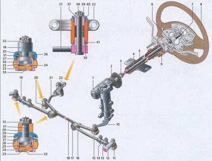
Figure 3.11- Screw type of steering mechanism
1-steering gear; 2-seal; 3-cardan joint; 4-steering shaft; 5-steering column tube; 6-contact ring; 7-nut; 8-steering wheel;
9-bearing; 10-steering bipod; 11-hinge of the side rod end; 12-pivot lever; 13-tie collar; 14-adjusting tube; 15-hinge of the bipod rod; 16-side rod; 17-side rod hinge; 18- bipod thrust; 19-tie rod end; 20-pendulum arm hinge; 21-pendulum arm; 22-pendulum arm bracket; 23-threaded plug; 24-conical spring; 25-support heel; 26-rod eye; 27-hinge housing ;
28-plastic spacer sleeve; 29-rubber seal of the side link hinge; 30-eye of the swing arm or bipod link; 31-ball pin; 32-hinge pin nut; 33-cotter pin of the threaded plug; 34-plastic cracker; 35-rubber seal of the hinge bipod rods; 36-metal spacer sleeve; 37-pendulum arm pin; 38-pendulum arm pin nut; 39-bushing; 40-rubber protective sleeve; 41-rubber protective sleeve.
The screw mechanism is also called "ball screw nut". While developing this system, the designers replaced the "worm" with a special screw with a ball nut attached to it. On the outer side of the nut there are teeth, which come into contact with the same sector roller as in the previous system.
In order to reduce friction, the developers proposed to place ball channels between the sector roller and the nut. Thanks to this solution, it was possible to significantly reduce friction, increase recoil and facilitate handling. However, the presence of the same complex system of rods, large dimensions and inconvenient shape of the screw mechanism led to the fact that the screw system was also recognized as unadapted to modern conditions.
However, some well-known car manufacturers still use the screw-ball nut mechanism in the manufacture of cars with longitudinal motor... Such mechanisms have nissan cars Patrol, Mitsubishi pajero and others.
Rack type steering mechanism
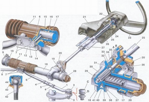
Figure 3.12 - Rack and pinion steering mechanism
1-tip of the steering rod; 2-ball joint of the tip; 3-pivot arm; 4-locknut; 5-rod; 6-inner tips of the steering rods; 7-bolts of fastening the steering rods to the rack; 8-inner tips of the steering rods; 9- steering gear mounting bracket; 10-steering gear support; 11-protective cover; 12-connecting plate; 13-locking plate; 14-silent block; 15-damping ring; 16-support bushing of the rack; 17-rail; 18-steering box ; 19-clamping bolt of the coupling; 20-lower flange of the elastic coupling; 21-upper part of the cladding casing; 22-damper; 23-steering wheel; 24-ball bearing; 25-steering shaft; 26-lower part of the cladding casing; 27- steering shaft mounting bracket; 28-protective cap; 29-roller bearing; 30-drive gear; 31-ball bearing; 32-retaining ring; 33-protective washer; 34-sealing ring; 35-bearing nut; 36-boot; 37-stop O-ring; 38-stop ring of the stop nut; 39-rack stop; 40-spring; 41-stop nut; 42-ball pin hinge; 43-protective cap; 44-ball pin insert; A. mark on the boot; B. mark on the steering box; C. surface of the ball joint; D. the surface of the swing arm.
Rack and pinion is the most common steering device. The strength of this design lies in its simplicity. This simple and progressive mechanism is used in the production of 90% of cars. The steering rack device is based on the main element - the shaft-rack. The rack-shaft is equipped with transverse teeth. A gear is located on the steering shaft, which engages the teeth of the steering shaft and moves the rack.
By using this system, it was possible to minimize the number of pivot joints and save significant energy. Each wheel is "supposed" to have two hinges and one rod. For comparison: in the "screw-ball nut" system, the wheel corresponds to three rods, in the "worm" mechanism - five rods.
Steering rack provided an almost direct connection between the steering wheel and the wheels, which means that it increased the ease of driving several times. Such steering gear the car made it possible to change the direction of movement with a minimum number of turns of the steering wheel.
Another advantage of the rack and pinion design is the size and shape of the crankcase. With its small size and elongated shape, the crankcase can fit anywhere in the car. Automakers place the crankcase above the engine, below the engine, in front or behind, based on the vehicle model.
Rack and pinion mechanism made it possible to achieve almost instant reaction of the wheels to the steering wheel turn. This system made it possible to create high-speed cars with a modern, improved control system.
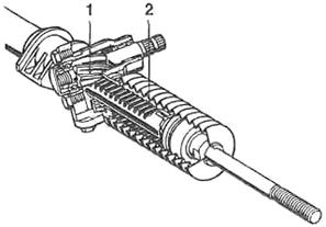
1 - gear: 2 - toothed rack
Figure 3.13 - Rack and pinion steering gear
The steering mechanism includes a steering wheel, a shaft enclosed in steering column, and a steering gear associated with the steering gear. The steering mechanism allows you to reduce the force applied by the driver to the steering wheel to overcome the resistance that arises when turning the steered wheels of the machine due to friction between the tires and the road, as well as deformation of the soil when driving on dirt roads.
The steering gear is mechanical transmission (for example, toothed), installed in the housing (crankcase) and having a gear ratio of 15 - 30. The steering mechanism reduces the force applied by the driver to the steering wheel connected by means of the shaft to the gearbox by so many times. The greater the gear ratio of the steering gear, the easier it is for the driver to turn the steered wheels. However, with an increase in the gear ratio of the steering gear for turning at a certain angle of the controlled wheel connected through the drive parts with the output shaft of the gearbox, the driver needs to turn the steering wheel at a greater angle than with a small gear ratio... When the vehicle is moving with high speed it is more difficult to make sharp turns at a high angle, because the driver does not have time to turn the steering wheel.
Steering gear ratio:
Up \u003d (ap / ac) \u003d (pc / pp)
where ap and ac are the angles of rotation of the steering wheel and the output shaft of the gearbox, respectively; Рр, Рс - the effort applied by the driver to the steering wheel and the effort at the output link of the steering mechanism (bipod).
So, to turn the bipod by 25 ° with the steering gear ratio equal to 30, the steering wheel must be turned by 750 °, and with Up \u003d 15 - by 375 °. With an effort on the steering wheel of 200 N and a gear ratio Up \u003d 30, the driver creates a force of 6 kN at the output link of the gearbox, and with Up \u003d 15 - 2 times less. It is advisable to have a variable steering gear ratio.
At small angles of rotation of the steering wheel (no more than 120 °), a large gear ratio is preferable, which provides easy and precise control of the vehicle when driving at high speed. When low speeds a small gear ratio allows at small angles of rotation of the steering wheel to obtain significant angles of rotation of the steered wheels, which ensures high maneuverability of the car.
When choosing the gear ratio of the steering mechanism, it is assumed that the steered wheels should turn from the neutral position to maximum angle (35 ... 45 °) not more than 2.5 turns of the steering wheel.
Steering mechanisms can be of several types. The most common of these are "worm-three-ridged roller", "worm-gear" and "screw-ball nut-rack-pinion". The gear in the steering mechanism is made in the form of a sector.
The steering mechanism converts the rotational movement of the steering wheel into angular movement of the steering arm mounted on the output shaft of the steering gear. When driving a fully laden vehicle, the steering gear, as a rule, should provide a force on the steering wheel rim of no more than 150 N.
The steering wheel angle (play) for trucks should normally not exceed 25 ° (which corresponds to a shower length of 120 mm measured at the rim of the steering wheel) when driving truck in a straight line. For other types of vehicles, the steering wheel play is different. Backlash occurs due to wear in the operation of steering parts and misalignment of the steering mechanism and drive. To reduce friction losses and protect the steering gear parts from corrosion, special gear oil is poured into its crankcase, which is attached to the machine frame.
When operating the vehicle, it is necessary to adjust the steering mechanism. The steering gear adjusting devices are designed to eliminate, firstly, the axial play of the steering shaft or the driving element of the gearbox, and secondly, the backlash between the driving and driven elements.
Consider the design of the "globoidal worm-three-ridge roller" steering mechanism.
Figure: The steering gear of the "globoidal worm-three-ridge roller" type:
1 - steering gear housing; 2 - head, steering arm ral; 3 - three ridge roller; 4 - shims; 5 - worm; 6 - steering shaft; 7 - axis; 8 - bipod shaft bearing; 9 - lock washer; 10 - cap nut; 11 - adjusting screw; 12 - bipod shaft; 13 - oil seal; 14 - steering bipod; 15 - nut; 16 - bronze bushing; h - adjustable depth of engagement of the roller with the worm
Globoidal worm 5 is installed in the crankcase 1 of the steering gear on two tapered roller bearings, which well perceive the axial forces arising from the interaction of the worm with the three-ridge roller 3. The worm pressed onto the splines on the end of the steering shaft 6 provides, with a limited length, good engagement of the roller ridges with a worm cut. Due to the fact that the action of the load is dispersed over several ridges as a result of their contact with the worm, as well as the replacement of sliding friction in engagement with much lower rolling friction, high wear resistance of the mechanism and a sufficiently high efficiency are achieved.
The axis of the roller is fixed in the head 2 of the shaft 12 of the steering arm 14, and the roller itself is mounted on needle bearings, which reduce losses when the roller is scrolling about the axis 7. The bearings of the steering arm shaft are, on the one hand, a roller bearing, and on the other, a bronze bushing 76. The bipod is connected to the shaft by means of small splines and secured with a washer and nut 15. An oil seal 13 is used to seal the bipod shaft.
The engagement of the worm with the ridges is carried out in such a way that, in a position corresponding to the rectilinear movement of the machine, free run there is practically no steering wheel, and as the steering angle increases, it increases.
Adjustment of the steering shaft bearings tightening is carried out by changing the number of gaskets installed under the crankcase cover, with its plane resting on the end face of the extreme tapered roller bearing. The adjustment of the engagement of the worm with the roller is carried out by displacing the steering arm shaft in the axial direction using an adjusting screw 11. This screw is installed in the side cover of the crankcase, closed from the outside with a cap nut 10 and fixed with a lock washer 9.
On heavy-duty vehicles, steering mechanisms of the "worm-side sector (gear)" or "screw-ball nut-rack-pinion" type are used, which have a large contact area of \u200b\u200bthe elements and, as a result, low pressure between the surfaces of the gearbox working pairs.
The steering gear of the "worm-side sector" type, the simplest in design, is used on some cars. Meshing with the worm 2 enters the lateral sector 3 in the form of a part of a gear with spiral teeth. The lateral sector is made as a whole with the bipod shaft 1. The bipod is located on a shaft mounted on needle bearings.
The gap in engagement between the worm and the sector is not constant. The smallest clearance corresponds to the center position of the steering wheel. The engagement gap is adjusted by changing the thickness of the washer located between the side surface of the sector and the cover of the steering gear housing.
The design of the "screw-ball-nut-rail-sector" steering mechanism is shown in the figure. Steering wheel shaft by cardan transmission connected to a screw 4 interacting with a ball nut 5 fixed by a locking screw 15 in the piston-rail 3. The screw and nut threads are made in the form of semicircular grooves filled with balls 7 circulating along the thread when the screw rotates. The extreme threads of the nut are connected by a groove 6 with an outer tube that circulates the balls. The rolling friction of these balls on the thread during the rotation of the screw is negligible, which leads to a high efficiency of such a mechanism.

Figure: Steering gear of the "worm-side sector" type:
1 - bipod shaft; 2 - worm; 3 - lateral sector

Figure: Steering gear type "screw-ball nut-rail-sector":
1 - cylinder cover; 2 - crankcase; 3 - piston rack; 4 - screw; 5 - ball nut; 6 - gutter; 7 - balls; 8 - intermediate cover; 9 - spool; 10 - control valve body; 11 - nut; 12 - top cover; 13 - plunger spring; 14 - plunger; 15 - locking screw; 16 - toothed sector (gear); 17 - shaft; 18- bipod; 19 - side cover; 20 - retaining ring; 21 - adjusting screw; 22 - ball pin
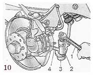
Figure: 1. Steering:
1 - side thrust:
2 - bipod;
3 - medium thrust;
4 - pendulum lever;
5 - adjusting clutch;
6 — lower ball joint of the personal suspension;
7 - right steering fist;
8 - the upper ball joint of the front suspension;
9 - the right lever of the steering knuckle,
10 - pendulum arm bracket;
11 - the right side member of the body;
12 - oil filler plug;
13 - steering gear housing;
14 - steering shaft;
15 - facing casing of the steering shaft;
16 - steering wheel;
17 - pipe of the upper support of the steering shaft;
18 - steering shaft bracket;
19 - left side member of the body;
20 - clamping clamps of the adjusting clutch;
21 left steering knuckle.
Possible malfunctions steering BA3-2106, their causes and methods of elimination:
...
INSPECTION, INSPECTION AND STEERING ADJUSTMENT
In the event of malfunctions in the steering (knocking, increased free play of the steering wheel or, conversely, its tight rotation, etc.), inspect the steering parts. Inspect in next order... Clean the steering gear parts and the steering box from contamination. Set the wheels to the straight ahead position.
By turning the steering wheel to both sides, check that:
Free play of the steering wheel does not exceed 5 ° (when measured along the wheel rim, no more than 18-20 mm);
- no knocking occurs in the joints, joints and steering mechanism;
The steering housing and swingarm bracket are firmly attached (tighten if necessary threaded connections);
There is no free play in the ball joints of the rods and in the pendulum arm bracket, and the worm shaft does not move in the axial direction;
The effort to turn the steering wheel (when installing the front wheels on a smooth plate) does not exceed 245 N (25 kgf).
Turning the adjusting couplings of the side links, make sure that their clamps are tightened securely.
Check the condition of the ball joints and rubber protective caps as follows.
BALL JOINT CHECK. STEERING RODS
First of all, check the movement of the rod ends along the axis of the fingers. To do this, using the lever and support, move the tip parallel to the axis of the finger.
The axial movement of the tip relative to the pin should be 1-1.5 mm. This movement indicates that. that the bushing of the pin is not jammed in the seat of the rod end and will mix with the pin, compressing the spring. Replace the joint with a jammed insert.
Swinging the steering wheel in both directions, check the lack of free play in the steering link joints by touch. If free play is felt in the ball joint, replace the rod end or steering rod assembled.
Check the condition of the protective rubber caps on the ball joints of the steering rods. The cap must be replaced if it is cracked, torn, or peeled from the rim, or if grease seeps out when squeezed by hand.
If the protective caps are in good condition and ensure cleanliness inside the hinges, the service life of the latter is practically unlimited. If moisture, dust, etc. enter the hinge premature wear of its parts occurs.
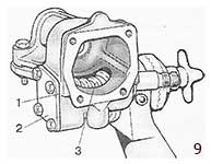
CHECKING AND ADJUSTING THE CLEARANCE IN THE BEARINGS OF THE STEERING GEAR WORM
Set the front wheels to position straight motion and, turning the steering wheel in either direction, check if the distance between the end of the housing 7 (Fig. 2) of the steering mechanism and the tip of the steering shaft changes. Distance change: This is an indication of the worm bearing play.
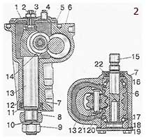 Figure: 2. Section of the steering box housing:
1 - plate of the bipod shaft adjusting screw;
2 - adjusting screw of the bipod shaft;
3 - nut of the adjusting screw;
4 - oil filler plug;
5 - steering gear housing cover;
6 - worm;
7 - steering gear housing;
8 - bipod;
9 - nut for fastening the bipod to the shaft;
10 - spring washer nuts for fastening the bipod;
11- bipod shaft oil seal,
12 - bronze bipod shaft sleeve;
13 - bipod shaft;
14 - bipod shaft roller;
15 - worm shaft;
16 - top ball bearing;
17 - lower ball bearing;
18 - shims;
19 - bottom cover of the worm bearing;
20 - roller axis;
21 - needle bearing;
22 - worm shaft oil seal.
To adjust the clearance in the worm bearings, turning the steering wheel to the left by 1-1.5 turns, unscrew the bolts securing the bottom cover 19 and drain the oil from the steering box housing. Remove the bottom cover remove one of the shims 18 or replace it with a thinner one.
NOTE. The shims are available as spare parts with a thickness of 0.10 and 0.15 mm. After securing the bottom cover, check again for axial movement of the worm in the bearings. If there is no movement, fill the steering box with 0.215 l of transmission oil. Check the steering effort by placing the front wheels on a smooth plate. It should not exceed 245 N (25 kgf).
CHECKING AND ADJUSTMENT OF THE CLEARANCE IN THE ENGAGING OF THE ROLLER WITH THE WORM
After making sure that there is no axial displacement of the worm in the bearings, press out the pins of the ball joints from the holes in the bipod with a puller А.47035 and disconnect the rods from the bipod, while maintaining the straight position of the front wheels.
Shaking the bipod by the head, check. whether there is a gap in the engagement of the roller and the worm. There should be no perceptible free play of the bipod within the 30 ° steering wheel rotation to either side of the neutral position. If you feel free movement of the bipod, loosen the nut 3 (Fig. 5-2) of the adjusting screw and, lifting the lock washer, tighten the adjusting screw 2 until the gap is eliminated. Do not over-tighten the adjusting screw. Then, while holding the adjusting screw with a screwdriver, tighten the nut 3.
After making sure the bipod does not move, connect the ball pins to the bipod. Check the steering effort. If it exceeds 245 N (25 kgf), then loosen the adjusting screw 2.
STEERING GEAR BA3-2106
REMOVAL AND INSTALLATION
Withdrawal. Disconnect the wires from battery and remove the cover of the signal switch. Remove the steering wheel. Remove both halves of the steering shaft shell. Remove the instrument panel and disconnect the turn signal and headlamp switch plugs from the wiring harness plugs.
Disconnect the wires from the ignition switch terminals and, after unscrewing the fastening screws and drowning the lock latch, remove the ignition switch.
NOTE
If it is necessary to remove only the crankcase of the ruble mechanism, then unscrew the bracket mounting bolts and the bolt securing the steering shaft to the worm shaft, and then slightly slide the steering shaft with the bracket into the interior and place a stand under the shaft so that it does not hang on the wires.
Loosen the clamp of fastening of the pipe of the upper support of the steering shaft and remove it together with the switch of direction indicators and headlights, having previously unlocked the steering shaft from the anti-theft device.
Remove the bracket 13 (Fig. 3) fastening the steering shaft. Remove the seal 8 of the steering shaft. Having unscrewed the bolt 7 securing the steering shaft to the worm shaft, remove the steering shaft into the body interior.
![]() Figure: 3. Steering parts:
Figure: 3. Steering parts:
1 - nut;
2 - flat washer;
3 - an adjusting washer;
4 - bolt for painting the steering box housing to the body;
5 - steering gear housing;
6 - spring washer;
7 - bolt of fastening of the tip of the steering shaft on the worm shaft;
8 - shaft seal:
9 - bolt for fastening the rubber seal to the body;
10 - steering shaft;
11 - steering wheel fastening nut;
12 - steering wheel;
13 - steering shaft bracket;
14 - bolt of fastening of the steering shaft bracket.
Using the A.47035 puller, press out the ball pins of the steering rods from the hole in the bipod.
Remove the steering box housing.
NOTE. While removing the steering box housing, note the number and location of shims 3 between the side member and the crankcase in order to refit them when installing the crankcase. This is to maintain the alignment of the steering shaft and the worm shaft.
 Install the steering gear in the reverse order to removal. In this case, before finally tightening bolts 1 and 3 (Fig. 4) fastening the steering housing and the steering shaft bracket, temporarily put the steering wheel on the shaft, turn the shaft two or three times to the left and to the right.
In this case, the shaft and other parts take correct position (self-installing) thanks to oval holes in the crankcase and bracket.
NOTE. It is possible to separately assemble the steering shaft with seal, bracket, ignition switch, turn signal and headlight switch, steering wheel and install this unit on the vehicle.
Figure: 4. Installing the steering gear on the car:
1 - bolts for fastening the steering box to the body;
2 - bolt of fastening of the steering shaft to the worm shaft;
3 - bolts of fastening of the steering shaft bracket to the body;
4 - plastic sleeve;
5 - steering shaft mounting bracket
6 - adjusting washers to ensure the alignment of the worm shaft and the steering shaft.
DISASSEMBLY AND ASSEMBLY OF THE STEERING GEAR
 Disassembly. Drain the oil from the steering box. Fix the crankcase on the bracket A.74076 / R with the support A.74076 / 1.
Unscrewing the nut securing the steering arm 3 (Fig. 5) and removing spring washer, remove the bipod with the A.47043 puller. Having unscrewed the fastening bolts, remove the cover 12 (Fig. 6) of the steering box housing together with the adjusting screw 8, the adjusting plate 9. the lock washer 10 and the locknut. Remove from the crankcase 1 shaft 7 bipod assembly with a roller.
After unscrewing the mounting bolts, remove the cover 3 of the worm shaft thrust bearing together with the shims 4.
Figure: 5. Removing the bipod:
1 - puller А.47043;
2 - bipod shaft of steering etching;
3 - bipod;
4 - bracket A. 74076 / R
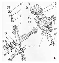 Figure: 6. Steering gear reducer details:
1 - crankcase;
2 - bipod;
3 - lower crankcase cover;
4 - shims;
5 - outer ring of the worm shaft bearing;
6 - separator with balls;
7 - bipod shaft;
8 - an adjusting screw;
9 - adjusting plate;
10 - lock washer.
11 - worm shaft,
12 - upper crankcase cover;
13 - sealing gasket;
14 - bipod shaft sleeve:
15 - worm shaft oil seal;
16 - bipod shaft oil seal.
With the worm shaft 11, push the outer ring 5 of the bearing out of the crankcase and take out the shaft together with the cages 6 of the bearings. Remove the worm shaft oil seal 15 and the bipod shaft oil seal 16.
Using a mandrel 67.7853.9541, press out the outer ring of the upper bearing (fig. 7).
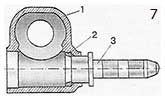 Figure: 7. Removing the outer ring of the upper worm bearing:
1 - steering gear housing;
2 - outer ring of the worm's upper bearing;
3-amendment 6 7.7853.9541
Assemble the steering mechanism on the bracket A.74076 / R in the reverse order to disassembly. Press the outer ring of the upper bearing of the worm with a mandrel 67.7853.9541, rearranging the nozzle on the mandrel handle with the reverse side.
After adjusting the gap in the engagement of the roller and the worm, check with a dynamometer the friction torque of the worm shaft, which should be equal to 88.2-117.6 Ncm (9-12 kgf.cm) when turning the worm shaft by 30 ° both to the left and to the right from the middle position and should decrease smoothly to 68.6 Ncm (7 kgfcm) when turning from an angle of 30 ° to the stop. 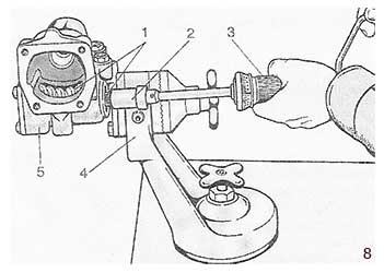
 After installing the worm in the steering gear housing and securing the bottom cover, check the friction moment of the worm shaft using a dynamometer 02.7812.9501 (Fig. 8) and head A.95697 / 5; it should be within 19.6-49 Ncm (2-5 kgf.cm).
If the torque turns out to be less than the specified one, reduce the thickness of the shims 2 (Fig. 9) and if more, increase it.
After installing the bipod shaft, check that there is no play in the engagement of the roller with the worm in the positions of the worm shaft turned to the right and left by 30 ° from the neutral position of the bipod.
Remove any gap in the engagement with the adjusting screw 2 (see Fig. 2) and tighten the lock nut 3.
At the end of the assembly, check the angles of rotation of the bipod from the neutral position, which should be 32 ° 10 "± 1 both to the left and to the right to the stop of the bipod in the bolt heads, pour 0.215 liters of transmission oil into the housing of the steering mechanism.
INSPECTION AND REPAIR OF THE STEERING GEAR
Carefully inspect the roller and worm running surfaces for signs of wear, binding, dents or marks. Replace worn and damaged parts. Check the gap between the bushings and the bipod shaft, which should not exceed 0.1 mm. If the clearance is greater than the specified, replace the bushings using a mandrel A.74105.
On the inner surface of the bipod shaft bushings there are spiral grooves that extend only to one side of the bipod. When pressing the bushings, position them so that their ends with groove exit are inside the crankcase bore, and the groove outlets are opposite each other. The ends of the bushings should sink into the crankcase bore by 1.5 mm.
Lubricate new bushings before pressing transmission oil... After pressing into the crankcase, finish the bushings with a reamer A.90336 to a size of 28.698-28.72 mm. Mounting clearance between the bipod shaft and the bushings should be within 0.008-0.051 mm. Check the ease of rotation of the bipod shaft roller.
The worm and roller bearings must rotate freely, without jamming; there should be no wear or damage on the surface of the rings and balls.
Check the runout of the steering shaft journal relative to the average spline diameter of the shaft end. To check, the lower end of the shaft is put on a special mandrel, which is installed on the prism. When turning the mandrel on the prism, the runout of the bearing journal of the shaft should not exceed 3 mm. If the shaft is deformed, then straighten it on a hand press. Check the axial clearance between the head of the adjusting screw 8 (see Fig. 6) and the groove of the bipod shaft 7. The clearance should not exceed 0.05 mm. If it is larger, then replace the shim 9 with a thicker one.
NOTE. Spare parts are supplied in eleven sizes of shims, from 1.95 mm to 2.20 mm; the increase in each dimension is 0.025mm.
STEERING RODS AND BALL JOINTS BA3-2106
REMOVAL AND INSTALLATION
 Unscrew and remove the nuts that secure the side link ball pins to the pivot arms. With a puller A.47052 (Fig. 10), remove the ball pins from the tapered seats on the levers.
Unscrew and unscrew the nuts securing the ball pins of the middle and side links to the bipod and to the swingarm. Using the A.47035 puller, remove the fingers from the corresponding sockets on the levers and remove the rods.
Install the steering linkage in the reverse order of removal. Tighten all the nuts of the ball pins with a torque wrench followed by a split pin. If the cut of the nut does not coincide with the hole for the cotter pin, then turn the nut at an angle less than 60 ° to ensure the cotter pin. After installing the links, adjust the toe-in of the front wheels.
INSPECTION AND REPAIR
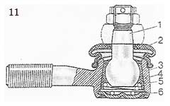 Check the condition of the protective caps 2 (fig. 11) as described above (see “Inspection, check and adjustment of the steering control”), if damaged, replace.
Figure: 11. Section of the ball joint of the steering link:
1 - ball pin;
2 - antisplash cap,
3 - hinge body;
4 - insert;
5 -spring;
6 - plug.
Check the condition of the ball joints of the rods by the radial and axial clearance. If you feel free play in the ball joint, as well as when dirt, sand gets into the joint, corrosion appears on the ball pin, and full use travel of the bearing pad - replace the hinge with the rod end.
PENDULUM ARM BRACKET
REMOVAL AND DISASSEMBLY
To remove the pendulum arm bracket, separate the pendulum arm from the ball pins of the middle and lateral right rods by undoing and unscrewing the nuts first and removing the ball pins from the lever sockets with a puller A. 47035. Then unscrew the bolts securing the bracket to the side member and remove the bracket.
Fasten the bracket in a vise, expand and unscrew nut 4 (Fig. 12), then remove washers 3 and 6 and pendulum arm 1 assembled with axis 9, washer 10 and self-locking nut 11, remove seals 7 and you press bushings 8 ...
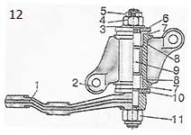 Figure: 12. Sectional view of the pendulum arm bracket:
1 - pendulum arm;
2 - bracket body;
3 - washer;
4 - an adjusting nut;
5 - cotter pin;
6 - upper washer;
7 - sealant;
8 - sleeve:
9 - lever axis;
10 - lower washer;
11 - self-locking nut.
CHECK
Check the condition of the pendulum arm axle bushings: if you find ovality or an unacceptable gap between them and the axle, replace the bushings with new ones. Check axle for ovality and damage, if necessary replace it with a new one. Make sure the pendulum arm is free of deformation; otherwise, replace it with a new one.
ASSEMBLY AND INSTALLATION
Before assembly, grease the pendulum arm axle bushings and fill the space between them with LITOL-24 grease. Assemble the pendulum arm bracket in the reverse order of disassembly.
If the axle 9 was replaced (see Fig. 12), then tighten the self-locking nut 11 of the lever fastening with a torque wrench. Washer 6 is installed by pushing up. After tightening the nut 4, the lever in the horizontal position must not rotate under its own weight. It must rotate under the action of a force of 9.8-19.6 N (1-2 kgf) applied at its end.
If the adjusting nut 4 is over-tightened, unscrew it. lift washer 6 and tighten again. Secure the bracket to the side member with two self-locking nuts and flat washers and tighten the nuts with a torque wrench. Connect the ball pins to the pendulum arm.
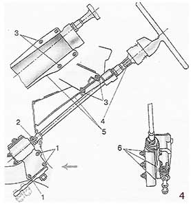
During the operation of the car, when it is moving on the roadway, the driver, as a rule, needs to coordinate the direction of its movement, as well as to decrease or increase its speed, stop and park. Every car enthusiast knows that all these operations "fall on the shoulders" of such movement mechanisms, which include steering and. In this article, we will touch on the steering mechanism, the main task of which is to ensure the movement of the car in the direction set by the driver.
The steering structure includes a steering gear and a steering gear. The main character of our article will be the steering bipod, which is one of the components of the steering mechanism. In addition to the bipod in the design of the steering mechanism (for example, worm-type) also includes a steering wheel with a shaft, a pair of "worm-roller", as well as a case of a worm pair. We will not touch on these details, but we will consider in more detail the device of the steering bipod, on what principle it works and how the bipod can be replaced if it malfunctions.
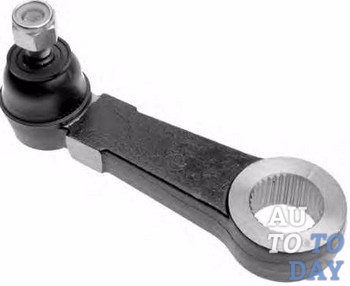
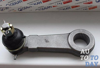
1. Bipod steering device
 An extremely important part such as the steering bipod (connecting rod) is usually used on vehicles with standard suspension systems and steering with parallelogram transverse links. Every car enthusiast will be able to say with confidence that given type steering and suspension systems are used in the design of most RWD vehicleas well as many light trucks.
The design of a bipod typically includes a splined arm, which in turn connects to the bearing threaded rod and seat, as well as the steering gear. A protective coating on the underside of the bearing threaded rod can prevent contamination of the bearing and seat. The top of the support pin attaches to the center link of the steering gear.
The movement of the steering shaft is directly dependent on the rotational movements that the driver makes while driving. The steering bipod is attached to the same shaft of the steering mechanism, which is put into operation as a lever and converts the force from turning the steering mechanism into mechanical for the movement of the steering drive. In other words, we can say that the steering bipod is designed to transfer force from the sector shaft to the longitudinal thrust. As you know, the bushing shaft rotates in two bushings, which are pressed into the steering gear housing.
 On needle bearing, which is located at the upper end of the shaft, there is a roller that produces rotational movements, on the lower end of the shaft, which has tapered splines, and the aforementioned bipod, which is attached to the end with a nut.
It is important to remember that there are two double depressions in the spline hole of the steering arm and there are two double ridges on the shaft. Based on this, the installation of the bipod on the shaft is mono performed only in one position.
So, let's summarize the design of the steering arm and its purpose as part of the steering mechanism. The steering bipod is an important part of attaching the middle link of the steering linkage to the steering shaft, as well as an executive part of the steering gear, it is capable of reciprocating rotation in a given sector depending on rotation.
2. The principle of operation of the steering bipod
 By what principle does the bipod of the steering mechanism work? The principle of operation of the part can be considered using the example of a worm steering gear. Its work is as follows: during the rotation of the steering wheel, all the force from the rotation can be transmitted to the worm gear of the column.In turn, the "worm" rotates the driven gear, which directly drives the steering bipod into operation. As we said, the bipod connects to the middle tie rod and the other end of the rod attaches to the swingarm.
The aforementioned arm is usually mounted on a support and rigidly attached to the vehicle body.With the help of crimp couplings, side rods are connected to the steering ends, which extend from the "pendulum" and the bipod. The tips, in turn, are connected to the hub. At the moment of turning, the steering arm sends force to the side link and to the middle lever at the same time. The middle lever, by inertia, drives the second lateral link, which leads to turning the hubs, and, accordingly, the wheels.
3. Replacing the steering bipod
Like all other automotive parts, the bipod breaks down sooner or later. In this case, you need to replace the bipod. And, as already "experienced" drivers say, this operation is quite expensive and, moreover, rather complicated.
 Anyone faced with the problem of replacing the bipod can argue that first you need to "beat" the frame cross member, which is located below the gearbox, at a fairly small distance from the bipod. The main problem is that the cross member cannot be unscrewed, or even done with it, but it significantly blocks the bipod, making it difficult to access it. But still there is a way out! Here is a rough diagram for you to remove the bipod and make a replacement. So let's get started ...
First, you need to unscrew the pendulum arm. Then you can remove the pendulum-tip of the bipod from the steering linkage, after the operation done, you should not be in the way. Next, you need to try to get the key to the nut of the bipod tip and loosen it. Then, the matter is small. We unscrew the gearbox, and lifting it higher, carefully and delicately try to gradually knock out the bipod pendulum with a hammer, or using a puller. After it is removed, you can replace it with a new one, and you can also update the swingarm.
So, with such simple actions, you can replace the bipod at home, but experts still advise you to contact technical centers in such a situation. So the choice is yours. In any case, we sincerely wish you the best of luck!
Subscribe to our feeds in