The UAZ-469 wiring diagram combines all devices and devices used in a car. In the event of malfunctions in the operation of the system, the full operation of the car can cause difficulties for the car owner, therefore, all breakdowns must be promptly eliminated. You can learn more about malfunctions, as well as wiring prevention, from this material.
What is included in the wiring diagram?
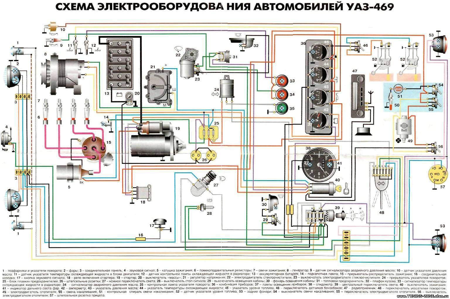
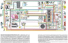
Above is the form of the wiring diagram.
Regardless of which UAZ you are using - old or new - the main components of the electrical network are as follows:
- Dashboard. The main sensors and indicators are displayed on it, indicating that one or another device is turned on. The tidy allows the driver to know at what speed he is moving, how much fuel is left in the tank, what is the crankshaft speed and what is the engine temperature. In addition, the tidy has a lot of bulbs that light up synchronously with the inclusion of certain devices.
- Accumulator battery. The battery is an integral part of any car, it allows you to power the equipment of the car when the engine is turned off, and also helps the ignition system to start the power unit. If the battery is discharged, it will not work to start the engine in the traditional way - you will need to either recharge it or try to start from the pusher.
- Generator device, failure of which will also lead to the inability to start the engine. This node provides voltage to all devices and devices used in the car while driving.
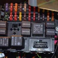
- Fuse box. This device contains all safety devices designed to protect electrical circuits and devices against overvoltage. If a power surge occurs in the network, then the fuse will take the main blow (by the Ben & Ice Video Master channel).
Common faults
As for breakdowns in the work of the electrical wiring of the Ulyanovsk product automobile plant, then they are:
- Battery discharge. As we already reported, without battery normal work motor will be impossible, the same applies to electrical equipment. Battery discharge can occur for various reasons. Due to the evaporation of electrolyte or its leakage as a result of damage to the battery case, damage to the plates inside the structure, or their short circuit. Usually such problems are caused by wear and tear of the device or its incorrect operation.
- Failure of the safety device. Its burnout can occur as a result of wear or a power surge. Before installing a new fuse, ring the circuit to ensure there are no surges. If they do occur, then you need to determine the cause and eliminate it, otherwise the problem will recur.
- Broken wire. This problem is relevant not only for UAZ, but also for other cars. To avoid breaks, wires should be routed away from moving body parts.
- There is no contact with the device. This usually occurs as a result of a broken wire, but if it is intact, then the problem lies in the contact. The end of the wiring could simply come off or oxidize. Oxidation is one of the main problems in domestic cars.
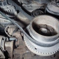
- Failure of the generator. The design of the generating unit itself is quite complex, so there can be many problems in its operation. If the generator itself is working, but not correctly, first of all it is necessary to diagnose its belt - it may be overtightened or too loose, in this case the problem will be solved by adjusting it.
Preventive measures
What preventive measures will save the car's electrical network from malfunctions:
- with the engine off, limit the use of electrical equipment, as the battery will drain faster;
- from time to time carry out diagnostics of the battery performance and check its charge;
- provide reliable insulation of the wiring;
- never use homemade fuses.
The main command vehicle of the armed forces - this is how the UAZ 469 SUV can be characterized. And indeed, having replaced the GAZ-69 in 1972, it secured this honorable duty for many years, proving the correct design and main components with its endurance and reliability.
Historical reference
Traditionally, the UAZ 469 was produced in two versions:
- Cargo-passenger version - 7 pieces and 100 kg of luggage;
- Commanding version - 2 seats for passengers and 600 kg of luggage.
For reference: regardless of the version, the UAZ 469 can tow a trailer with a gross weight of 850 kg.

1945 industry normal
According to the old vehicle classification system, in force since 1945, the UAZ 469 was produced under this name, using an alphanumeric name:
- The letter abbreviation UAZ stands for Ulyanovsk Automobile Plant;
- 469 is an ordinal factory index assigned by the enterprise itself to its models and developments.
For reference: according to the industry standard of 1945, a certain numbering was assigned to each car plant. For MZMA, which produced Moskvich 408 and 412, these are numbers from 400 to 449, for the Ulyanovsk Automobile Plant, these are numbers from 450 to 484, etc.
Industry normal 1966
Although at the time of the release of the UAZ 469 car (1972), a new industry classification system was adopted (industry standard OH 025270-66), the car factory continued to use the name according to the old standard.
However, in 1985, the automaker was forced to change the name, according to the current requirements:
- the car was assigned a four-digit number - 3151;
- according to new system, the car can be referred to in the documentation as UAZ 3151.
For reference: industry standard ОН 025270-66 prescribes to determine the type of cars by the engine displacement, length and weight. The first number indicates the class of the car, the second - the type (truck or car), the third and fourth - the factory model index.
All further modifications and new models were named by the car plant according to the current standards. In particular, the UAZ Patriot, which appeared in 2005, according to the industry classification, received the "correct" designation - UAZ-3163. For better identification, the factory instructions contained both names.

Engine compartment
The main power unit For many years, the UAZ 469 was an inline 4-cylinder UMZ-451MI of the carburetor type. The engine displacement was 2445 cubic meters. cm, power - 75 hp.

With this engine produced by Ufa motor plant UAZ 469 held out on the factory assembly line until 1985.
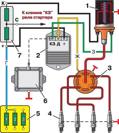
It was distinguished by a simple single-wire 12-volt ignition circuit, which consisted of (according to the numbering):
- storage battery (joint stock bank);
- mechanical switch "mass";
- electronic battery charge voltage regulator;
- generator alternating current;
- ammeter on the instrument panel;
- ignition lock (switch);
- contact group an ignition breaker;
- directly the ignition distributor (distributor);
- condenser built into the distributor;
- ebonite distributor cover with leads for high-voltage wires;
- ignition distributor slider;
- spark plugs;
- high voltage wires from the ignition coil;
- additional coil resistance;
- starter relay;
- directly high-voltage ignition coil;
- electric starter.

For reference: on the above black and white diagram of the ignition system, letters indicate the wiring on the UAZ 469 by the color of the wires. K - red, O - orange, G - blue; F - purple and H - black (in the capital letters of the names).
New modifications legendary SUV got more modern motors and a modified electrical circuit.
In particular, the UAZ Patriot wiring diagram includes:
- electronic fuel injection system;
- contactless system ignition;
- climate control system inside the car;
- system alarm etc.
conclusions
The UAZ 469 car has established itself as a fairly reliable off-road vehicle for multipurpose use. The civilian population is actively using it for their own purposes also due to the fact that it can be serviced with your own hands, using factory documentation and the advice of craftsmen.
What is the difference between the UAZ 31514 wiring diagram? The car received a completely different ignition system from the previous one, it became contactless. At the same time, the reliability remained at the highest level, as in the UAZ 2206. The choice of this particular achievement modern automotive industry associated not only with wiring, but also with the quality of the overall assembly. All models, including UAZ 390945 and others, amaze with their reliability, durability, strength, and comfort of use.
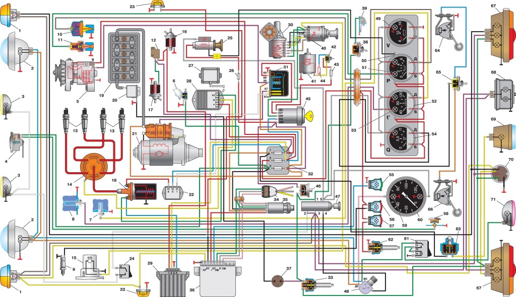
1 - front lamp;
2 - headlight;
3 - sound signal;
4 - fuse;
5 - side direction indicator;
6 - additional resistance;
7 - heater switch;
8 - heater fan electric motor;
9 - lighting lantern engine compartment;
10 - generator;
11 - turn signal and alarm relay;
12 - spark plugs;
13 - heater resistance (resistor);
14 - starter relay;
15 - ignition coil;
16 - distributor sensor;
17 - switch;
18 - accumulator battery;
19 - "mass" switch;
20 - electric washer;
21 - emergency vibrator;
22 - fuse box;
23 - oil pressure indicator sensor;
24 - coolant temperature sensor;
25 - coolant overheating sensor;
26 - sensor emergency pressure oils;
27 - insufficient level sensor brake fluid; 28 - starter;
29 - headlight relay;
30 - portable lamp socket;
31 - indicator switch parking brake;
32 - brake signal switch;
33 - speedometer;
34 - indicator of insufficient level of brake fluid;
35 - parking brake engagement indicator;
36 - indicator of inclusion of direction indicators;
37 - switch-on indicator high beam headlights;
38 - carburetor microswitch;
39 - wiper;
40 - block of the EPHH system;
41 - wiper relay;
42 - solenoid valve EPHH systems;
43 - signal lamp emergency oil pressure;
44 - signal lamp for overheating of the coolant;
45 - central light switch;
46 - alarm switch;
47 - fuel level indicator;
48 - coolant temperature gauge;
49 - oil pressure indicator;
50 - voltmeter;
51 - interior lighting plafond;
52 - interior light switch;
53 - right steering column switch;
54 - horn switch;
55 - fuel level sensor;
56 - left steering column switch;
57 - fuel level sensor switch;
58 - cigarette lighter *;
59 - switch for rear fog lamp;
60 - thermal (bimetallic) fuse;
61 - ignition switch;
62 - ignition relay;
63 - reverse light switch;
64 - rear lamp;
65 - additional flashlight brake signal *;
66 - reversing light;
67 - rear fog lamp;
68 - license plate lamp;
69 - trailer socket *.
* Installed on parts of cars.
The presented model is more reliable, for example, 390994, the injector of which gives many problems to customers, requires close attention to temperature sensors. For the electrical equipment of the UAZ 469 or UAZ 3303, the system was used more simply, there were no such problems, and the later electrical circuit of the UAZ 2206 is much simpler, which did not affect the reliability and quality in any way.
Features of the model and its equipment
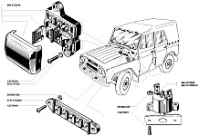
The wiring diagram is still striking in its quality. The assignee of this vehicle became another model 31514, which began to be produced in 1993, immediately won the circle of its admirers. The new models differ significantly from the previous ones. Not only the design has been improved, but the wiring has also been improved. For example, the UAZ 390994 wiring diagram, the injector of which could be inconvenient, did not have a special temperature sensor. New models have contactless ignition... The node includes:
- low-voltage ignition coil;
- electronic transistor switch;
- distributor, i.e. distributor sensor;
- electrical additional resistance;
- special emergency breaker;
- fuses (block installed).
For example, type 390994, whose injector was causing problems on high revs, did not have such a high-quality and well-developed wiring. And the lack of such a network element does not ensure that the damper is closed for intake manifold... Maintenance of such a system is inconvenient, the absence of only one sensor makes 390994, whose injector is so “problematic,” not so much in demand. The situation was solved by using better system and additional cables.
Wiring components for UAZ 469, UAZ 390945 and other models
Wiring diagram UAZ 3151 4 includes 69 positions, there is a possibility additional connection special fog lights, but requires the installation of a circuit breaker type 343.01.03. It will mount directly on dashboard in a convenient location. General scheme The machine's wiring includes an extensive list of different devices.
This is a front light, headlights that are easy to replace if necessary. TO common system the sound signal is also connected. Further, the UAZ wiring diagram includes a special fuse, additional resistance. The chain has a connection to the side direction indicators, a switch for the heater is immediately placed.
The wiring supplies the generator, there are connection points for the lantern that illuminates the engine compartment, outlets for the fan motor for the heater. Modern UAZ wiring provides spark plugs powered by it. A relay for indicators is installed, it is used to ensure the operation of an emergency, rotary signaling.
The electrical circuit has outputs to the coil, a starter relay, there is a special sensor-distributor, a switch. On one site there are the following points: turn off the masses, alarm indicator, storage battery, electric washer. There is a separate connection for the fuse box and such sensors:
- emergency pressure for oil;
- fuel readings;
- for oil pressure gauge;
- overheating of the used coolers;
- temperatures of the used coolers;
- determining the level of the brake fluid.
1.Low-voltage ignition coil; 2.Transistor electronic switch; 3.Sensor-distributor (distributor); 4.Electric spark plugs; 5. Block of fuses; 6.Emergency breaker; 7.Additional electrical resistance.
The electrical circuit includes connection points for the starter, speedometer, wiper and relay for it, EPHH unit, voltmeter. There are such components:
- relay for car headlights;
- sockets used to power portable lamps;
- parking brake switches, braking systems.
For electrical equipment of the UAZ 31512 (14) or UAZ 390945, the installation of switches is used:
- for brake signal;
- for the parking brake;
- alarm;
- interior light lamps;
- sound signal;
- rear fog lamp;
- ignition;
- reversing light.
The electrical equipment of UAZ-31512, UAZ-31514 and UAZ-31519 vehicles is made according to a single-wire circuit. The negative terminals of the sources and consumers of electricity are connected to the body and the rest of the vehicle units, which act as a second wire. Onboard network direct current, with a nominal voltage of 12 volts. Protection of electrical circuits is organized through the fuse box.
To switch the main circuits of the car, a combined ignition switch is used, consisting of a contact part and a mechanical anti-theft device with lock. When the engine is not running, all consumers are powered by a storage battery, and after starting the engine - from alternating current with a built-in rectifier unit. When the generator is running, the battery is charged.
When the engine is running on idling, the generator rotor speed and, accordingly, the supplied current are insufficient to provide power to powerful consumers, such as headlights, windshield wipers, electric fan, alarm. In this mode, the battery will be discharged.
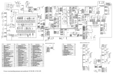
Location and purpose of electrical circuit fuses on-board network UAZ-31512, UAZ-31514 and UAZ-31519.
To protect the electrical circuits of the car's external lighting from overload, a bimetallic fuse 29.3722 or similar is used, which is installed under the instrument panel on the left. Three 10 Amp fuses are installed in the PR103 fuse box, mounted on the bulkhead of the engine compartment. They protect:
No. 1 - chains control devices;
No. 2 - direction indicator chains;
No. 3 - alarm and sound signal circuits.
Fuse No. 1 is located closer to the starboard side of the vehicle. Heater fan motor power supply circuit protected fuse with a rated current of 6 Amperes. The fuse is attached to the wiring harness next to the heater switch. Cars UAZ-31512, UAZ-31514 and UAZ-31519 can be equipped with other additional fuses, depending on the configuration.
Checking the electrical circuits of the UAZ-31512, UAZ-31514 and UAZ-31519 on-board network under voltage.
Live circuits are also checked with an ammeter. The voltmeter is connected in parallel with the tested device or circuit section. Measurement range 0-15 or 0-25 Volts DC. The negative wire (probe) is connected to ground, the positive wire is connected to consumers or current sources. By voltage drop, it is possible to determine the malfunction of the supply circuit - open circuit, oxidation of contacts, etc., as well as a short circuit in the consumer.
To test live circuits, you can also use control lamp with a power of no more than 3-4 W, designed for a voltage of 12 Volts, for example, the AMN12-3 lamp used in the instrument panel.
The ammeter must have an upper measurement limit of at least 10 Amperes DC, as well as overload protection. We connect the ammeter in series with the tested device. The plus of the device is connected to the current source, and the minus to the plus of the consumer. If the current is less than the required one, then the electrical circuit is faulty, and if it is more, a short circuit has occurred in the consumer.