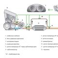
The Toyota JZGE engine range is a series of gasoline automotive in-line six-cylinder engines that replaced the M range. All engines in the series have a DOHC gas distribution mechanism with 4 valves per cylinder, engine sizes: 2.5 and 3 liters.
The engines are designed for longitudinal placement for use with rear-wheel drive or all-wheel drive transmission. Produced from 1990-2007. The successor was the V6 line of GR engines. The 2.5 liter 1JZ-GE was the first engine in the JZ line. This engine was equipped with a 4 or 5-speed automatic transmission gear. The first generation (until 1996) had a classic "distributor" ignition, the second - "coil" (one coil for two spark plugs). In addition, the second generation was equipped with a VVT-i variable valve timing system, which made it possible to smooth the torque curve and increase power by 14 hp. from. Like the rest of the series engines, the timing mechanism is driven by a belt, the engine also has only one drive belt for attachments... If the timing belt breaks, the engine will not be destroyed. The engine was installed on cars: Toyota Chaser, Cresta, Mark II, Progres, Crown, Crown Estate, Blit.


Specifications 1JZ-GE, 1st and (2nd) generation:
Type: Petrol, injection Volume: 2 491 cm3
Maximum power: 180 (200) HP, at 6000 (6000) rpm
Maximum torque: 235 (255) Nm at 4800 (4000) rpm
Cylinders: 6. Valves: 24. The piston diameter is 86 mm, the piston stroke is 71.5 mm.
The compression ratio is 10 (10.5).
Operating conditions, subtle points in repair, problems of engines 1JZ-GE 2JZ-GE.
Diagnostics: Date from the scanner.
The developers have laid down a sufficiently informative diagnostic date, by which it is possible to make an accurate analysis of the operation of the sensors using the scanner. We have laid down the necessary sensor tests. An exception is the ignition system, which is practically not diagnosed by the scanner. The date presents the work of all sensors and electronic units without frills. In graphical mode, it is informative to view the oxygen sensor switching. Verification tests available fuel pump, change of injection time (duration of injectors opening), activation of VVT-i, EVAP, VSV, IAC valves. The only drawback, there is no test - the power balance with alternate disconnection of the injectors, but this flaw can also be easily bypassed - by disconnecting the connectors from the injectors to determine idle cylinder... In general, most problems are recognized by scanning, without using additional equipment... The main thing is that the scanner is tested and with the correct display of parameters and symbols.
Below are screenshots from the scanner display.
Photo. Unrealistic oxygen sensor data (signal circuit short to heating circuit).

Photo Error software scanner

Photo: A window with a list of tests for activating executive organs.

Photo Continued

Photo: Displays the current data of oxygen sensors in graphical mode.

Photo. A fragment of the current data from the scanner.

Sensors engine 1JZ-GE 2JZ-GE.
Knock sensor.
The knock sensor detects the detonation in the cylinders and transmits the information to the control unit. The block corrects the ignition timing. In the event of a malfunction of the sensors (there are two of them), the unit detects an error 52.54 P0325, P0330.
As a rule, the error is fixed after a "strong" overglowing on x \\ x or when moving. It is not possible to check the sensor performance on the scanner. I need an oscilloscope for visual control signal from the sensor. Sensor location. Sensor filling.


Oxygen sensor (s).
The oxygen sensor (s) problem on this motor is standard. Breakage of the sensor heater and contamination of the active layer with combustion products (decrease in sensitivity). The active element of the sensor was repeatedly broken off. Examples of sensors.


In the event of a sensor malfunction, the unit detects error 21 P0130, P0135. P0150, P0155. You can check the performance of the sensor on the scanner in the graphical view mode or using an oscilloscope. The heater is checked physically with a tester - resistance measurement.
Figure: An example of oxygen sensor operation in graphical view mode.

Figure: Error codes recorded by the scanner.
Temperature sensor.
A temperature sensor registers the temperature of the motor for the control unit. In the event of an open or short circuit, the control unit fixes error 22, P0115.
Photo. Temperature sensor readings on the scanner.

Photo. Temperature sensor, and its location on the motor block.


Typical sensor malfunction is incorrect data. That is, as an example, on a hot motor (80-90 degrees), the readings of the cold motor sensor (0-10 degrees). In this case, the injection time greatly increases, a black soot exhaust appears, and the stability of the engine at idle speed is lost. And starting a hot engine becomes very difficult and long. Such a malfunction is easy to fix on the scanner - the motor temperature readings will randomly change from real to minus. Replacing the sensor is somewhat difficult (access is difficult), but when the right approach and the use of specials. tool - easy to do. (On a cooled engine).
Valve VVT-i.
The VVT-i valve causes a lot of problems for owners. The rubber rings, in its design, over time shrink into a triangle and press the valve stem. The valve wedges - the stem gets stuck in an arbitrary position. All this leads to the passage of oil (pressure) into the VVT-i clutch. The clutch turns the camshaft. In this case, the engine starts to stall at idle speed. Either the revolutions become greatly increased, or they float. Depending on the malfunction, the system fixes errors 18, P1346 (for 5 seconds, a timing violation is recorded); 59, P1349 (At a speed of 500-4000 rpm and a coolant temperature of 80-110 °, the valve timing differs from the required by ± 5 ° for 5 or more seconds); 39, P1656 (valve - open or short circuit in the valve circuit vVT-i systems for 1 or more seconds).

Below in the photographs are the valve installation location, catalog number, valve disassembly and examples of "triangular" rubber rings, the date with the changed vacuum due to the valve wedge. Example of a stuck valve stem and oil filter location.


The system check consists in testing the operation of the valve. The scanner provides a test for switching on the valve. When the valve is turned on at idle speed, the engine stalls. The valve itself is checked physically for sticking of the stem stroke. Replacing the valve is not particularly difficult. After replacement, you need to reset the battery terminal to bring the speed back to normal. Repair of the valve is also possible. It is necessary to flare it and replace the O-ring. The main thing when repairing is to observe correct position valve stem. Before repairing, it is necessary to make control marks for installing the core, relative to the winding. You also need to clean the filter mesh in the VVT-i system.
Crankshaft sensor.
Conventional inductive sensor. Generates impulses. Fixes the crankshaft speed. The oscillogram of the sensor is as follows.

The photo shows the location of the sensor on the motor and the general view of the sensor.


The sensor is quite reliable. But in practice, there were cases of turn-to-turn closure of the winding, which led to a breakdown in generation at certain speeds. This - provoked the limitation of revolutions when throttling - a kind of cutoff. A typical malfunction associated with the breaking off of the marker teeth of the gear (when replacing the crankshaft oil seal and dismantling the gear). When disassembling, mechanics forget to unscrew the gear stopper.

In this case, starting the motor becomes either impossible, or the motor starts, but no idle move - and the motor stalls. If the sensor breaks (no readings), the motor does not start. The block fixes the error 12.13, P0335.
Camshaft sensor.
The sensor is installed on the block head, in the area of \u200b\u200bthe 6th cylinder.


The inductive sensor generates pulses - it counts the camshaft rotation speed. The sensor is also reliable. But there were sensors, through the case of which, engine oil flowed, and the contacts were oxidized. There were no breaks in the sensor winding in my practice. But the occurrence of an error on the inoperability of the sensor - when the belt jumped (synchronization violation) was enough.

Therefore, if an error P340 occurs, it is necessary to check the correct installation of the timing belt.
MAP manifold absolute pressure sensor.
Sensor absolute pressure in the intake manifold is the main sensor, according to the indications of which the fuel supply is formed. The injection time directly depends on the sensor readings. If the sensor is faulty, then the unit fixes error 31, P0105.


As a rule, the cause of the malfunction is a human factor. Either a tube that has flown off the sensor fitting, or a wire break or a connector that is not fixed until it clicks. The performance of the sensor is checked according to the readings on the scanner - a line indicating the absolute pressure. By this parameter, abnormal intake leaks are easily detected. Or, together with other codes, the operation of the VVT-i system is evaluated.
Idle stepper motor.
On the first motors, a stepper motor was used to control the load speed, warm-up and idle.


The motor was very reliable. The only problem is contamination of the motor rod, which led to a decrease in idle speed and engine stops, under loads - or at traffic lights. The repair consisted in dismantling the motor from the case throttle, and cleaning the stem and body from deposits. Also, when removed, the motor O-ring changes. Dismantling of the stepper motor was only possible by partially removing the throttle body.
Idle valve IAC.
On the next generation of motors, solenoid valve (idle valve IAC) for speed control. There were many more problems with the valve. He often got dirty and wedged.


Figure: Control impulses.

At the same time, the engine speed became either very high (remained warm) or very low. The decrease in revs was accompanied by strong vibration when the loads are turned on. You can check the operation of the valve using a test on the scanner. It is possible to programmatically open or close the valve shutter and observe the change in speed. Before dismantling, check the control pulses.


If the speed does not change in the test, the valve is cleaned. Disassembling the valve presents a certain difficulty. The bolts that fix the winding are unscrewed with a special tool. Five-pointed star.


The repair consists in flushing the valve curtain (eliminating jamming). But there are pitfalls here. With abundant flushing, grease is flushed out of the rod bearings. This leads to re-seizure. In such a situation, repairs are only possible by relubricating the bearings. (Lowering the valve body into heated oil and then removing excess lubricant during cooling) If problems arise with the electronic valve coil, the control unit fixes error 33; P0505.
The repair consists in replacing the winding. You can change the speed slightly by adjusting the position of the winding in the housing. After any manipulations with the valve, the battery terminal must be reset.
The throttle position sensor has been installed on all types of engines. In the first version, when replacing, he required adjustment of the idle sign. In the second, the installation was carried out without adjustments. And on the electronic shutter, a special sensor adjustment was required.


If the sensor is faulty, the unit detects error 41 (P0120).
The correct operation of the sensor is monitored by the scanner. On the adequacy of the switching of the idle sign and in the graph the correct voltage change during throttling (without voltage dips and surges). The photo shows a fragment of the date from the engine scanner with an idle valve. Sensor reading at idle 12.8%

If the sensor is broken, there is a chaotic speed limitation, incorrect automatic transmission switching. And on a motor with email. damper - complete shutdown of the damper control. Replacing the sensor is not difficult. On the first engines, replacement includes correct installation and adjustment of the idle indicator. On the second type of motors, the replacement consists in the correct installation and reset of the battery. And by email. throttle adjustment is carried out using a scanner. You need to turn on the ignition, turn off the email. press the damper motor with your finger and set the TPS reading on the scanner to 10% -12%. Then connect the motor connector and reset the errors. Then start the engine and check the sensor readings. When the engine is idling, the readings should be in the region of 14-15%.
In the photo, the correct readings of the sensor on the electric throttle in idle mode.

Installed on systems with email. throttle. In case of a malfunction, the unit fixes the error P1120, P1121. When replacing, no adjustment is required. It is checked by a scanner and physically measuring the resistance of the channels.


Electronic choke.
The idle valve and mechanical choke with a cable drive were replaced in 2000 by electronic choke... Completely robust robot design.

The throttle cable was left in order to be able to control the damper in the event of a malfunction (allows you to slightly open the damper with the gas pedal almost fully depressed). The throttle and gas pedal position sensors and the motor are mounted on the damper body. This gives an advantage in renovation. Electronic throttle problems are related to sensor failure. On average, after 10 years of operation, the active resistive layer on the potentiometers is erased. The repair consists in replacing the sensors, setting the TPS and then resetting the control unit.
Gas distribution engine 1JZ-GE 2JZ-GE.
The timing belt is changed every 100 thousand kilometers. Installations and timing belt are checked during diagnostics. Initially, they check for the absence of codes on the camshaft, then the ignition angle with a stroboscope.

And if there are prerequisites, they check the labels, physically combining them, or with an oscilloscope to view the synchronization of the crankshaft and camshaft sensors.

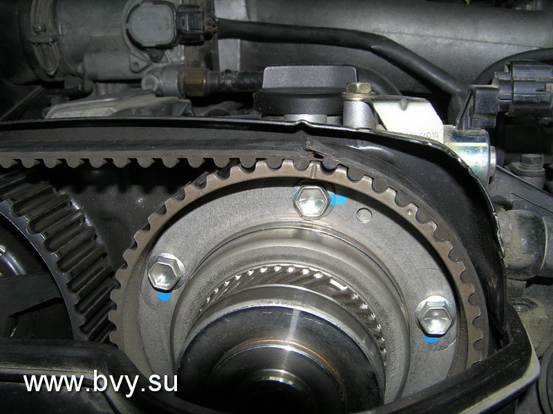
Belt change on 1JZ-GE 2JZ-GE motors is carried out in conjunction with roller oil seals and a hydraulic tensioner. On the top cover there is a photo of the correct removal of the VVT-I coupling. Well-defined timing marks on the belt and on the gears leave little to no chance of incorrect belt installation. If the timing belt breaks, there is no fatal meeting of the valves with the piston. The photos below show examples of belt wear, timing belt number, removed gears, timing marks and hydraulic tensioner.


Ignition system engine 1JZ-GE 2JZ-GE.
Distributor.
The distributor is standard. Inside there are position and speed sensors and a slider.


The contacts of the high-voltage wires in the cover are numbered. The first cylinder is marked for installation. The only inconvenience is the installation of the distributor in the head. The drive is gear, but it also has marks for correct installation... Distributor problems are usually related to oil leaks. Either through the outer ring or through the stuffing box inside. The outer rubber ring changes quickly without problems, but replacing the oil seal causes certain difficulties. Shrink-fit marker gear - the process of replacing the oil seal negates. But with a competent approach and skillful hands, this problem can be solved. The size of the gland is 10x20x6. The electrical problems of the distributor are standard - wear or sticking of the coal in the cap, contamination of the contacts of the cap and slider, and an increase in gaps due to burnout of the contacts.
Ignition coil and switch, high voltage wires.


The take-out coil practically did not fail, it worked flawlessly. An exception is pouring water when washing the motor, or insulation breakdown during operation with broken high-voltage wires. The switch is also reliable. Has a CIP design and reliable cooling. Contacts are signed for quick diagnostics. High voltage wires are the weak link in this system. With an increase in the gaps in the spark plugs, a breakdown occurs in the rubber tip of the wire (strip), which leads to the "tripping" of the motor. It is important during operation to produce planned replacement candles on the run. Structurally, the wire of the 6th cylinder is susceptible to water ingress. This also leads to breakdowns. The 4th cylinder is completely inaccessible for diagnostics and inspection. Access is only possible when dismantling a part intake manifold... The 3rd cylinder is susceptible to the ingress of antifreeze when dismantling the valve body - this should be taken into account during repairs. The operation of the ignition system is affected by oil leakage from under valve covers... The oil destroys the rubber tips of high voltage wires. The restyled engines were equipped with a DIS ignition system (one coil for two cylinders) without a distributor. With remote commutator and crankshaft and camshaft sensors.


The main failures are the breakdown of the rubber tips of the coils and wires, with wear of the spark plugs, the vulnerability of the 6th and 3rd cylinders, and the ingress of water, oil and dirt during general engine aging. In winter bays, there are frequent cases of destruction of the connectors of the coils and wires. Difficult access to the middle cylinders makes owners forget about their existence. Correct maintenance and seasonal diagnostics completely removes all these problems and hassles.
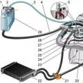
Fuel system Filter, injectors, fuel pressure regulator.
The average fuel pressure required for the engine to operate is 2.7-3.2 kg / cm3. When the pressure drops to 2.0 kg, there are dips during gas changes, power limitation, and lumbago in the intake. It is convenient to measure the pressure at the inlet to the fuel rail by first unscrewing the damper. It is also convenient to connect here for flushing the fuel system.

The fuel filter is installed under the underbody of the vehicle. The replacement cycle is 20-25 thousand kilometers. Substitution presents some difficulty. It is necessary that the tank is almost empty when replacing. Fittings on the tubes to the filter with a peculiar profile. They are unscrewed with great effort (to prevent fuel leakage). On cars since 2001, the filter has been moved to fuel tank and its replacement is not difficult. The fuel rail with injectors is located in an easily accessible place. The injectors are very reliable, easy to clean - when flushing the fuel system. The operation of the injectors is checked by an oscilloscope. When the internal resistance of the winding changes, the shape of the pulse changes. You can also check the operation of the injector and its relative "clogging" by measuring the current (current clamp). By current changes. The winding resistance is measured with a tester. The spray of the injector is checked at the stand - by visual inspection of the spray cone and the amount of filling for a certain time.
The photo shows the correct impulse.

Water ingress is detrimental to the injector. Since the date does not provide for a test for checking the operation of the cylinders, it is possible to determine the inoperative or ineffectively working cylinder by turning off the corresponding injector. Basis for flushing Lean mixture errors 25 (P0171), or the gas analyzer reading is a large amount of oxygen in the exhaust. The fuel pressure regulator is installed on the fuel rail. It is adjusted to relieve pressure in the return line above 3.2 kg. The mechanism breaks down when exposed to water. There were no other problems with him in my practice. The fuel pump is installed in the tank. Standard pump. Its performance is assessed by measuring the pressure (with the vacuum tube removed on the pressure regulator). When the working pressure drops to 2.0 kg, the engine loses power.
September 30th, 2010
TOYOTA Engines 1JZ-GE, 1JZ-GTE, 2JZ-GE, 2JZ-GTE, 1JZ-FSE (gasoline) - user manual / instructions for repair, maintenance and operation.
This manual includes step by step descriptions procedures for repair, operation and maintenanceconsidered device gasoline engines Toyota 1JZ-GE (2.5 L), 1JZ-GTE (2.5 L turbo), 2JZ-GE (3.0 L), 2JZ-GTE (3.0 L turbo) with multipoint injection fuel and 1JZ-FSE (2.5 l. D-4 New!) with direct fuel injection.
These units were installed on the model: Aristo, Chaser, Cresta, Crown, Majesta, Mark II, Soarer, Supraas well as on Lexus GS300.
The manual provides detailed information on the repair and necessary adjustments of engine mechanisms, system elements fuel injection (EFI), Systems direct injection fuel (D-4), variable valve timing systems (WT-i), ignition, starting and charging systems, instructions for using the self-diagnosis system, and also studied possible malfunctions and methods of their elimination, highlighted the mating dimensions of the main parts and the critical limits of their permissible wear.
A separate chapter of the manual includes wiring diagrams of engine control systems for various models.
The presented brochure is intended for Toyota car owners with the specified engines, service station specialists, car services, numerous mechanics from repair shops.
Abbreviations 3
Legend 3
Identification 3
Toyota engine maintenance and general inspection and adjustment procedures 4
Oil Precautions 4
Check engine oil 4
Changing engine oil and filter 4
Checking and replacing coolant 5
Check battery 5
Checking and cleaning air filter 6
Checking high voltage wires and spark plugs 6
Removing and checking high-voltage wires 6
Checking the spark plugs 6
Checking drive belts mounted units 7
Checking and adjusting the ignition timing 7
Checking the idle speed 8
Checking and adjusting the CO concentration at idle speed 8
Checking the pressure at the end of the compression stroke 8
JZ series engines (without WT-i). Mechanical part 9
Checking and adjusting thermal clearances in valves 9
Timing belt 12
Removal 12
Checking Timing Belt Components 14
Installation 15
Cylinder head 17
Removal 17
Installing the cylinder head 20
Cylinder block 24
Operations before disassembly 24
Final Engine Assembly 24
JZ series engines (with WT-i). Mechanical part 27
Checking and adjusting thermal clearances in the valves 27
Timing belt (type 1) 29
Withdrawal 29
Installation 30
Timing belt (type 2) 31
Removal 31
Installation 32
Cylinder head 34
Removal 34
Installation 35
Cylinder block 37
Pre-disassembly 37
Final assembly 37
1JZ-FSE engine. Mechanical 42
Checking and adjusting clearances in the valve drive 42
Timing belt 42
Removal 42
Installation 43
Cylinder Head 44
Removal 44
Installation 45
Cylinder block 46
Pre-disassembly 46
Final assembly 46
Engine - General Repair Procedures 48
Cylinder head 48
Dismantling the cylinder head 48
Checking, cleaning and repairing cylinder head parts 48
Cylinder head assembly 53
Cylinder block 54
Dismantling the block of cylinders 54
Checking the block of cylinders 57
Disassembly of the piston-connecting rod assembly 58
Checking the condition of the piston and connecting rod 58
Checking the crankshaft 60
Replacing crankshaft oil seals 60
Assembling the piston-connecting rod assembly 61
Cylinder block assembly 62
System WT-i 63
Description 63
Checking the elements of the WT-i system (1JZ-FSE) 64
Removing the camshaft gear BEma (UZ-FSE) 64
Gear installation camshaft (1JZ-FSE) 64
Removal and installation of the valve of the WT-I system (1JZ-FSE) 64
Operating principle (1JZ-GE, 2JZ-GE) 65
Turbocharging system 66
Description 66
Caution 66
Receiver (TwinTurbo) 67
Turbocharger (TwinTurbo) 67
Vehicle check 67
Removing the turbocharger 68
Checking the elements of the turbocharger 72
Installing a turbocharger 73
Aftercooler of charge air (TwinTurbo) 76
Turbocharger (1JZ-GTE after 1996) 77
Withdrawal 77
Installation 77
Checking the elements of the turbocharger 77
Checking the components of the turbocharging system 78
Turbocharging system (1JZ-GTE since 2000) 78
Lubrication system 80
Checking oil pressure 80
Oil pump 80
Withdrawal oil pump 80
Dismantling the oil pump 81
Checking the oil pump 82
Assembling the oil pump 82
Installing the oil pump 82
Oil cooler 84
Removing the oil cooler 84
Checking the oil cooler 84
Installing the oil cooler 84
Cooling system 85
Coolant pump 85
Removal 85
Installation 85
Check 86
Thermostat 86
Removal 86
Installation 87
Check 87
Radiator 87
Cleaning the radiator 87
Checking the radiator 87
Cooling fan 87
Checking on the engine 87
Checking the electric fan 88
Dismantling the electric fan 88
Assembling the electric fan 88
Checking the sensor switch for the coolant temperature 88
Checking the fan relay 88
Checking the main engine relay 89
Fuel injection system 90
Description 90
Precautions 90
Electrical Maintenance Precautions 90
Precautions for use with a mobile radio system 90
Air System Precautions 90
Electronic Control System Precautions 91
Handling Precautions fuel system 91
Diagnostic system 92
Description 92
CHECK ENGINE indicator (check engine) 92
Diagnostic code output (normal self-diagnosis mode) 92
Output of diagnostic codes (self-diagnosis in test mode) 93
Erase Diagnostic Code 93
Fault diagnosis with driving test 93
Diagnostic codes of malfunctions of the engine management system 95
Checking signals at outputs electronic unit management 104
Checking the elements of the injection system using an oscilloscope 129
Some technical data of the electronic control system 131
Fuel system 134
Fuel pump 134
Fuel pressure regulator 138
Fuel pressure pulsation damper 139
Injectors 140
Air supply system 149
Throttle body (2JZ-GTE, since 1992) 149
Throttle body (2JZ-GE, since 1992) 152
Throttle body (cTRC models, since 1992) 154
Throttle body (JZ series, since 1996) 155
Throttle body (JZ series since 2000) 158
Idle speed control valve (2JZ-GE, since 1992) 160
Idle speed control valve (2JZ-GTE, since 1992) 160
Idle speed control valve (JZ series, since 1996) 162
Intake Manifold Change System (ACIS) (since 1992) 162
Intake Manifold Change System (ACIS) (since 1996) 165
Electronic control system 166
Air mass meter (2JZ-GTE, since 1992) 166
Air mass meter (1JZ-GTE, since 1996) 167
The main relay of the fuel injection system 167
Fuel pump relay (since 1992) 168
Fuel pump control relay (2JZ-GE, 1JZ-GTE since 1992) 168
Electronic fuel pump control unit 168
Variable Resistor 168
Fuel pump resistor 169
Additional resistance of injectors (2JZ-GTE) 169
Electro-pneumatic valves (2JZ-GTE, since 1992) 169
Electro-pneumatic valve of the fuel vapor recovery system 170
Fuel pressure control solenoid valve (2JZ-GTE, since 1992) 170
Coolant temperature sensor and intake air temperature sensor 170
Intake air temperature sensor 171
Absolute pressure sensor in the intake manifold 171
Turbocharger pressure sensor (2JZ-GTE) 172
Knock sensor 172
Exhaust gas temperature sensor 173
Oxygen sensor (since 1992) 173
Oxygen sensors (since 2000) 174
Evaporative emission (EVAP) system (since 1996) 174
Valve WT 174
Fuel vapor recovery system (EVAP) (since 2000) 175
Fuel cut-off system for forced idle 175
Fuel vapor recovery system (EVAP) (foreign market models, after 1998) 175
Troubleshooting Algorithm oxygen sensor 177
Direct fuel injection system (D-4) 187
Description 187
The main design differences from the traditional injection system 187
Operating modes of engines D-4 (for domestic market) 187
Major problems with D-4 engines 187
Additional Precautions 187
Diagnostic system 188
Output of diagnostic codes 188
Erasing diagnostic code 188
Diagnostic codes of malfunctions of the engine management system 189
Voltage at the terminals of the electronic control unit 191
Checking the elements of the injection system using an oscilloscope 193
Some technical data read with a scanner 195
Fuel system 196
Car checks 196
Checking the Components 196
Injectors 196
Fuel pump and fuel filter 197
Air supply system 199
Throttle body 199
Checking the pneumatic drive 199
Removing and installing intake manifold 199
Electronic control system and toxicity reduction system 199
System valve WT-i 199
Coolant temperature sensor 200
Intake air temperature sensor 200
Fuel pressure sensor 200
Throttle position sensor 200
Evaporative emission (EVAP) 201
Valve eGR systems 201
Ignition system 202
Distributor ignition system (since 1990) 202
Description 202
Precautions 202
Spark test 202
Checking the ignition coil 202
Checking the ignition coils (1JZ-GTE) 203
Checking the position sensors of distribution and crankshaft (1JZ-GTE) 203
Valve check 203
Distributor, ignition 204
DIS-3 ignition system (since 1996) 204
Checking the ignition coils 204
Checking the position sensors of the camshafts and crankshafts 204
Switch 205
Starting system 206
Starter 206
Disassembly and assembly of the starter (with a conventional gearbox - type 1) 206
Disassembly and assembly of the starter (with planetary gear - type 2) 207
Starter check 209
Replacing the terminals of the traction relay 211
Checking the starter 212
Charging system 213
Precautions 213
Checks on the car 213
Dismantling the generator 213
Generator assembly 214
Checking the generator 215
Checking the rotor 215
Checking the stator 215
Checking brushes 215
Checking the rectifier unit 215
Checking bearings 215
Wiring diagrams 113
Designations used on electrical circuits 217
Wire color codes 217
Toyota Altezza
Scheme 1. Charging system. Starting system (models up to 05.2001) 218
Diagram 2. Engine and automatic transmission control system (models with 2JZ-GE engine) 219
Scheme 2 (continued). Engine management system and automatic transmission (models with 2JZ-GE engine) 220
Scheme 2 (continued). Engine management system and automatic transmission (models with 2JZ-GE engine) 221
Scheme 2 (continued). Engine management system and automatic transmission (models with 2JZ-GE engine). Electric drive of fans (models from 07.2001) 222
Scheme 3. Starting system (models with 2JZ-GE and 1G-FE (4WD) engine) 223
Toyota Crown 130-140
Diagram 1. Power supplies. Charging system 224
Scheme 2. Power supplies. Engine starting system 225
Diagram 3. Power supplies. Ignition system (1JZ-GE, 2JZ-GE). Ignition system (1G-FE) 226
Diagram 4. Power supplies. Engine management system (1JZ-GE, 2JZ-GE) 227
Scheme 4 (continued). Engine management system (1JZ-GE, 2JZ-GE) 228
Diagram 5. Power supplies. Engine management system (2JZ-GE modifications) 229
Scheme 5 (continued). Engine management system (2JZ-GE modifications) 230
Diagram 6. Engine management system (models with 1JZ-GE engine release from 10.1991) 231
Scheme 6 (continued). Engine management system (models with 1JZ-GE engine release from 10.1991) 232
Diagram 7. Engine management system (models with 2JZ-GE engine release from 10.1991) 233
Scheme 7 (continued). Engine management system (models with 2JZ-GE engine release from 10.1991) 234
Scheme 7 (continued). Engine management system (models with 2JZ-GE engine release from 10.1991) 235
Toyota Crown 150
Diagram 1. Engine management system (models with 1JZ-GE engine produced before 09.1999) 236
Scheme 1 (continued). Engine management system (models with 1JZ-GE engine produced before 09.1999) 237
Scheme 2. Engine management system (models with a 2JZ-GE engine produced before 07.1997) 238
Scheme 2 (continued). Engine management system (models with 2JZ-GE engine produced before 07.1997) 239
Scheme 3. Engine management system (models with a 2JZ-GE engine release before 07.1997-09.1999) 240
Scheme 3 (continued). Engine management system (models with 2JZ-GE engine release before 07.1997-09.1999) 241
Diagram 4. Engine management system (models with 1JZ-GE engine release before 09.1996-09.1999) 242
Scheme 4 (continued). Engine management system (models with 1JZ-GE engine produced before 09.1996-09.1999). Charging system 243
Diagram 5. Engine management system (models with 1JZ-GE engine release from 09.1999) 244
Scheme 5 (continued). Engine management system (models with 1JZ-GE engine release from 09.1999) 245
Diagram 6. Engine management system (models with 2JZ-GE engine release from 09.1999) 246
Scheme 6 (continued). Engine management system (models with 2JZ-GE engine from 09.1999) 247
Scheme 7. Charging system. Starting system (models from 09.1999) 248
Toyota Mark II 80
Scheme 1. Starting system 249
Scheme 2. Ignition system 250
Scheme 3. Fuel heating system. Charging system. System for increasing idle speed (7M-GE) 251
Diagram 4. Engine management system (models with 1JZ-GE engine) 252
Diagram 5. Engine management system (models with 1JZ-GTE engine) 253
Toyota Mark II 90
Scheme 1. Starting and ignition system 254
Scheme 2. Charging system. Low level warning system brake fluid... Cooling fan control 255
Diagram 3. Indicators and electronic system automatic transmission control (1JZ-GE) 256
Scheme 4. Engine management system (1JZ-GE) 257
Scheme 4 (continued). Engine management system (1JZ-GE). Locking system 258
Scheme 5. Engine management system (1JZ-GTE) 259
Scheme 5 (continued). Engine management system (1 JZ-GTE) 260
Scheme 6. Engine management system (2JZ-GE) 261
Scheme 6 (continued). Engine management system (2JZ-GE). Cigarette lighter and clock 262
Toyota Mark II 100
Scheme 1. System of starting and ignition 263
Scheme 2. Engine management system (models with 1JZ-GE engine produced before 08.1998) 264
Scheme 2 (continued). Engine management system (models with 1JZ-GE engine produced before 08.1998). Charging system 265
Diagram 3. Engine management system (models with 1JZ-GTE engine) 266
Scheme 3 (continued). Engine management system (models with 1 JZ-GTE engine) 267
Diagram 4. Engine management system (models with 2JZ-GE engine produced before 08.1998) 268
Scheme 4 (continued). Engine management system (models with 2JZ-GE engine produced before 08.1998) 269
Scheme 5. Engine management system (models of release up to 08.1998 with 1JZ-GE engine without ETCS) 270
Scheme 5 (continued). Engine management system (models up to 08.1998 with 1JZ-GE engine without ETCS). Overdrive (except for models with electronic control Automatic transmission) 271
Scheme 6. Engine control system (models of release up to 08.1998 with engine 1 JZ-GE, 2JZ-GE with ETCS) 272
Scheme 6 (continued). Engine management system (models up to 08.1998 with engine 1 JZ-GE, 2JZ-GE with ETCS) 273
Toyota Mark II 110
Scheme 1. Charging system 274
Scheme 2. Starting system 275
Diagram 3. Ignition system (models with engines 1JZ-GE and 1 JZ-GTE) 276
Diagram 4. Ignition system (models with 1JZ-FSE engine) 277
Diagram 5. Engine management system (models with 1JZ-GE engine) 278
Scheme 5 (continued). Engine management system (models with 1JZ-GE engine) 279
Scheme 5 (continued). Engine management system (models with 1JZ-GE engine) 280
Diagram 6. Engine management system (models with 1 JZ-GTE engine) 281
Scheme 6 (continued). Engine management system (models with 1 JZ-GTE engine) 282
Scheme 6 (continued). Engine management system (models with 1 JZ-GTE engine) 283
Scheme 6 (continued). Engine management system (models with 1 JZ-GTE engine). Switch lock 284
Diagram 7. Engine management system (models with 1JZ-FSE engine) 285
Scheme 7 (continued). Engine management system (models with 1 JZ-FSE engine) 286
Scheme 7 (continued). Engine management system (models with 1 JZ-FSE engine) 287
Scheme 7 (continued). Engine management system (models with 1 JZ-FSE engine) 288
General instructions for repairing Toyota 289 engines
Russian language
ISBN 5-88850-119-0
Format: PDF
Pages: 296
Attention!
By downloading this manual, you agree to delete the downloaded file from your computer after reading it. All content of the portal is obtained from free sources on the Internet, or freely distributed.
The portal administration is not responsible for illegal actions and any damage suffered by the copyright holders.
If you are the author / owner of the posted material, please contact us in order to provide users of the resource with another convenient alternative for review, or purchase a high-quality "original" directly from the publisher.
Close a certain pin to the ground and watch the blinking of the error light of the motor ECU. Before the year 96, the TE1 pin, after the year 96, the TS pin. 1W light bulb between pin W and + 12V. The conclusions must be connected directly to the brain, tk. when the motor is swapped without the donor's salon braid, a part of the diagnostic pad is not connected.
- 2. Diagnostics by scanner
the rope to it can be soldered on 2 transistors - in fact it is.
Actually, k-line exists after 2003, but it has its own tricks (the keyword gateway ecu).
Before 96, many are diagnosed with this.

The "old" scanner also reads some 2jz-ge, as well as all 1jz-gte from JZX100.
1jz-ge vvti manufactured before 98 (with mechanical choke and cable box) cannot be read by any scanner.
- 3. Popular mistakes when swapping a popular motor
- The ACIS damper does not open when pumping to the floor - the valve is not connected to the brain, or the vacuum receiver next to the starter is split, or the vacuum tubes are broken.
- Lights up check engine when gasping while parking - the HT pin of the brain is not connected to the lambda, or the lambda power is not connected, and / or the STA / NSW pins are incorrectly connected.
- The machine does not respond to the inclusion of ranges 2, L - pins 2, L of the brain are not connected, it is also possible STA, NSW
- All kinds of glitches ( extraneous noise, spontaneous stop, twitching) when reversing - pin R of the brain is not connected
- When connecting pins R, 2, L, it is important not to forget to check that power is supplied to the selector position limit switch (the counter next to the selector lever sticking out of the box) according to the diagram
- For motors with electronic choke
The only difference is the extra wires. For this thing to move, you need to apply ground to pin EC and a constant plus to + BM. In this case, if everything else is connected correctly, when incl. ignition from the damper you will hear itching and it will react to any movement of the pedal sensor.
- 7. Power attachment
- 8. ECU power supply
It should be noted that contact E2 is the output to the sensors and on most cars should not be called to ground. All motor scythe mass leads are bolted to the intake manifold.
The injectors and the ignition system are always connected directly to the ignition switch, so that if the brain and / or the main relay glitches, the engine can be turned off. Hinged, combined with + B of the diag.pads, is connected to the output of the main relay. If the brain has an MREL output, it should be switched on from there, otherwise, when the motor stops, the IAC will not take the position required for the subsequent start.
Article taken from the site
Toyota engine 1JZ-FSE / GE / GTE 2.5 l.
Toyota 1JZ engine specifications
| Production | Tahara plant |
| Engine brand | Toyota 1JZ |
| Years of release | 1990-2007 |
| Cylinder block material | cast iron |
| Supply system | injector |
| A type | inline |
| Number of cylinders | 6 |
| Valves per cylinder | 4 |
| Piston stroke, mm | 71.5 |
| Cylinder diameter, mm | 86 |
| Compression ratio | 8.5 9 10 10.5 11 |
| Engine displacement, cubic cm | 2492 |
| Engine power, hp / rpm | 170/6000
200/6000 280/6200 280/6200 |
| Torque, Nm / rpm | 235/4800
251/4000 363/4800 379/2400 |
| Fuel | 95 |
| Environmental standards | ~ Euro 2-3 |
| Engine weight, kg | 207-217 |
| Fuel consumption, l / 100 km (for Supra III) - city - track - mixed. |
15.0 9.8 12.5 |
| Oil consumption, gr. / 1000 km | up to 1000 |
| Engine oil | 0W-30 5W-20 5W-30 10W-30 |
| How much oil is in the engine | 5.1 (1JZ-GE Crown 2WD 1995-1998) 5.4 (1JZ-GE Crown 2WD 1998-2001) 4.2 (1JZ-GE Crown 4WD 1995-1998) 4.5 (1JZ-GE Crown 4WD 1998-2001) 3.9 (1JZ-GE Crown, Crown Majesta 1991-1992) 4.4 (1JZ-GE Crown, Crown Majesta 1992-1993) 5.3 (1JZ-GE Crown, Crown Majesta 1993-1995) 5.4 (1JZ-GTE / GE Mark 2, Cresta, Chaser for 2WD) 4.5 (1JZ-GTE / GE Mark 2, Cresta, Chaser for 4WD) 4.5 (1JZ-FSE 4WD) 5.4 (1JZ-FSE 2WD) 5.9 (1JZ-GTE Mark 2 from 10.1993) |
| Oil change is carried out, km | 10000
(better than 5000) |
| Engine operating temperature, deg. | 90 |
| Engine resource, thousand km - according to the plant - on practice |
- 400+ |
| Tuning - potential - without loss of resource |
400+ <400 |
| The engine was installed | Toyota Brevis Toyota Chaser Toyota Cresta Toyota Mark II Blit Toyota Progres Toyota Soarer Toyota Tourer V Toyota Verossa |
Faults and engine repair 1JZ-FSE / GE / GTE
Of all Toyota engines, the JZ series has become one of the most famous, perhaps even the most famous, thanks in large part to its incredible penchant for tuning, but let's start over. The JZ family consisted of two motors, the first was a 2.5 liter displacement and was called 1JZ, the second was 3 liters. -.
Let's talk about the first representative, the successor of the engine and the main competitor RB25 - this is an in-line six, in a cast-iron cylinder block, two-shaft, with 4 valves per cylinder, a timing belt drive here (belt replacement is carried out every 100 thousand km, and in the case breakage, the 1JZ valve does not bend, except for the FSE version), the variable geometry intake manifold ACIS, the cylinder head has been modified since 1996, the variable valve timing system at the VVTi inlet has appeared, the cooling system has been changed, and more. There are no hydraulic compensators for 1JZ, the valves are adjusted, if necessary, once every 100 thousand km, with adjusting washers.
Since 2003, the 1JZ-FSE has been superseded by the newer aluminum 4GR-FSE.
Toyota 1JZ engine modifications
1.1JZ-FSE D4 - 1JZ direct injection engine, compression ratio 11, power 200 hp. Produced from 2000 to 2007.
2. 1JZ-GE - basic atmospheric version of 1JZ. The first version, produced before 1996, had a compression ratio of 10 and developed 180 hp, after which changes were made, VVTi appeared, the connecting rods were changed, the cylinder head was modified, the degree rose to 10.5, the distributor in the ignition system was replaced with 3 ignition coils and etc. The power of the second generation 1JZ-GE has risen to 200 hp.
3.1JZ-GTE - turbo version of 1JZ-GE on two CT12A turbines blowing 0.7 bar, replaced by SHPG, cylinder head was developed with the participation of Yamaha, standard camshafts on 1JZ are in phase 224/228, lift 7.69 / 7.95 mm. In 1996, the engine was restyled, two turbines were changed to one ST-15B, VVTi was added, the compression ratio increased to 9, the power remained at the previous level (280 hp), but the moment grew, from 363 Nm, to 378 Nm.
Weaknesses 1JZ, malfunctions and their causes
1. 1JZ will not start. Usually the reason is flooded candles, twist and dry. If it doesn't help, replace the plugs. The 1JZ engine is afraid of washing and frost.
2. Troit the motor. The main reason for tripleting Jezets is described above, see also the coils. If the internal combustion engine is with vvti, check the VVTi valve.
3. Float turns. Change the VVTi valve and everything will work out. More reasons for swimming and the lack of warm-up speed: idle sensor / valve, throttle valve. After flushing the latter, the motor will run like a clock.
4. High fuel consumption for 1JZ. Check the oxygen sensor, mainly the reason is in the lambda probe. See more maf and filters.
5. Knocking in the engine. On engines with VVTi, the crackle is most likely caused by the VVTi clutch, their resource is not too long. In addition, unregulated valves (few people regulate them) and connecting rod bushings can knock. Noise can also be created by the belt tensioner bearing of the ancillary units, in this case replacing it will save.
6. Zhor of oil. The high oil consumption for 1JZ is not surprising, because the mileage on your engine is most likely terrible. To do decarbonization is not very effective, it is better to immediately change the valve stem seals and rings, and even better and more efficiently, replace the motor with a contract one and not know the troubles.
Among other things, the pump does not last long on 1 jizet (as on many toyotas), the viscous coupling does not last long, on the FSE versions there is a weak and rather expensive link of the injection pump, it walks about 80-100 thousand km. In spite of everything, all the above-mentioned problems are caused, rather, by the age of the internal combustion engine, the manner of operation, rather than the miscalculations of engineers. Nice, well maintained 1JZ, nwith normal maintenance, and the use of high-quality oil (5W-30), it is simply unkillable and its resource easily exceeds 500,000 km.
Toyota 1JZ-FSE / GE / GTE engine tuning
Turbo / Twin Turbo 1JZ
In tuning jazets, there is the only correct way to increase power, naturally, this is boost. There is no point in trying to convert 1JZ-GE into 1JZ-GTE, with the same crankshaft, the GTE block differs in oil channels and oil nozzles, in addition, building such a collective farm is a much more costly event than just buying and installing a contract Toyota 1JZ-GTE engine, their cost is not so too great. If you are a terribly stubborn person, then you can get confused with shafts with a phase of 264 ... 272, do the cylinder head porting, cold intake, throttle valve from 1JZ-GTE, put forward flow on a 2.5 ″ pipe ... in the end, you will still come to a twin turbo swap. wogo 1JZ-GTE. It will not be possible to completely remake the 1JZ, the height of the 2JZ block differs by 14 mm and you will have to install short connecting rods, as a result, we have increased loads on the connecting rods, cylinder walls, a tendency to oil consumption and other joys, for a powerful engine this is unacceptable.
In general, we have 1JZ-GTE, the usual boost is enough for urban tuning, so we put on the Walbro 255 lph pump, throw out the catalyst and build the exhaust on a 3 ″ pipe, full exhaust, without constrictions, cold air intake, this will allow to raise the pressure on the standard ECU from 0 , 7 bar to 0.9. Next, buy a Blitz brain boost (or another), a boost controller, a blow-off, an intercooler and blow 1.2 bars. Such a simple chip-exhaust-pump will raise the power by 100 hp, after which the standard injectors and turbines are finished.
If the 1JZ-GTE engine still doesn't work for you, then look further ...
Then you need to order a turbo kit based on the Garrett GTX3076R turbine, a thick 3-row radiator, an oil cooler, cold air intake, an 80 mm damper, a Walbro 400 lph pump, reinforced fuel hoses, 800 cc injectors, phase 264 shafts, 3.5 ″ exhaust pipe, setup on APEXI PowerFC or AEM Engine Management Systems. Such configurations provide up to 550-600 hp, automatic transmission for 1JZ, with such power, will definitely require amplification.
If this is not enough, then look for whales based on the Garrett GTX3582R, forging the motor on reinforced Carrillo connecting rods, force 1000 cc and blow up to 700-750 hp.
Up to 1000 hp 1JZ can be reached with the Garrett GT4202, but only a few do it ...
For an even greater increase in power, it is practiced to transfer the finished head, with everything accompanying, to the 2JZ unit, thereby obtaining a larger working volume, no unnecessary fuss, and a significantly increased power, popularly called such a motor 1.5JZ.
The 1JZ-GE engine can be safely called a legend created by the designers of the Japanese company Toyota. Why a legend? The 1JZ-GE was the first engine in the new JZ line, created in 1990. Now engines of this line are actively used in motorsport and in ordinary cars. 1JZ-GE became the embodiment of the latest technologies of that time, which are still relevant today. The engine has established itself as a reliable, easy-to-operate and relatively powerful unit.
Specifications 1JZ-GE
| Number of cylinders | 6 |
| Arrangement of cylinders | in-line, longitudinal |
| Number of valves | 24 (4 per cylinder) |
| A type | petrol, injection |
| Working volume | 2492 cm3 |
| Piston diameter | 86 mm |
| Piston stroke | 71.5 mm |
| Compression ratio | 10:1 |
| Power | 200 h.p. (6000 rpm) |
| Torque | 250 N * m (4000 rpm) |
| Ignition system | Trambler |
First and second generation
ATTENTION! Found a completely simple way to reduce fuel consumption! Don't believe me? An auto mechanic with 15 years of experience also did not believe until he tried it. And now he saves 35,000 rubles a year on gasoline!
As you can see, the toyota 1JZ-GE is not turbocharged and the first generation had a distributor ignition. The second generation was equipped with coil ignition, 1 coil was installed for 2 candles, and a VVT-i valve timing system.

1JZ-GE in Toyota Chaser
1JZ-GE vvti - the second generation with variable valve timing. The variable phases allowed to increase the power by 20 horsepower, smooth the torque curve, and reduce the amount of exhaust gases. The mechanism works quite simply, at low speeds the intake valves open later and there is no valve overlap, the engine runs smoothly and quietly. At medium revs, valve overlap is used to reduce fuel consumption without losing power. At high revs, the VVT-i provides maximum cylinder filling for increased power.
The first generation engines were produced from 1990 to 1996, the second generation from 1996 to 2007, all of them were equipped with four and five-speed automatic transmissions. Installed on:
- Mark II Blit;
- Chaser;
- Cresta;
- Progres;
- Crown.
Maintenance and repair
JZ series engines run normally on 92 and 95 gasoline. On 98th, he is worse to start, but has high productivity. There are two. The crankshaft position sensor is located inside the distributor, there is no starting nozzle. Platinum spark plugs need to be replaced every hundred thousand kilometers, but to replace them, you will have to remove the upper part of the intake manifold. The volume of the engine oil is about five liters, the volume of the coolant is about eight liters. Vacuum air flow meter. The one located near the exhaust manifold can be reached from the engine compartment. The radiator is cooled as standard by a fan attached to the water pump shaft.
Overhaul of 1JZ-GE may be needed after 300 - 350 thousand kilometers. Naturally standard maintenance and replacement of consumables. Probably the sore spot of the engines is the timing belt tensioner, which is only one and often breaks. Problems can also arise with the oil pump, if it's simple, then it is similar to the VAZ one. Fuel consumption for moderate driving from 11 liters per hundred kilometers.
1JZ-GE in JDM culture
JDM stands for Japanese Domestic Market or Japanese Domestic Market. This abbreviation formed the basis of the world movement, which began with the JZ series engines. In our time, probably, most of the engines of the 90s are installed in drift cars, since they have a huge reserve of power, are easy to tune, are simple and reliable. This is confirmation that 1jz-ge is a really good engine, for which you can safely pay money and are not afraid that you will stop at the side of the road on a long journey ...