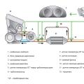
In this article I will present a diagram of the ignition system for a VAZ 2110 car, as well as the principle of its operation.

The content of the article:
The ignition system is one of the most important engine management systems in a car. This technology is intended to ignite a mixture of gasoline and air in the engine. This is ensured by the appearance of a spark. The ignition is part of electrical systems of the machine.
Car ignition system wiring diagram

The VAZ 2110 contactless ignition system consists of the following basic elements:
- car battery;
- generator;
- plug connector;
- ignition switch;
- distributor sensor;
- switch;
How the ignition system works and how it works
On the VAZ 2110, they abandoned such familiar ignition elements as the coil and distributor. So, a special ignition module is used here, which consists of high-energy control electronics, as well as a pair of coils. It is important to note that such a system does not require frequent servicesince there are no moving parts. The VAZ 2110 ignition system also does not require special adjustments, because for this a controller is installed here. He carries out all the settings and adjustments.
The ignition system is based on the “blank spark” method. This is a special method for distributing the spark. As you know, the cylinders in a car engine work in pairs (the 1st cylinder with the 4th, and the 2nd with the 3rd). So, the spark is triggered in two cylinders at once: the working spark is in the cylinder where the compression stroke of the mixture occurs, and the idle spark is in the one where the exhaust stroke is carried out. Because the current in the windings of the coils of the system is constant, it turns out that on the first candle the electrons move from the central electrode to the side electrode, and on the second - vice versa (from the side to the central one).
Depending on the type of engine, two types of spark plugs can be used on the VAZ 2110. So, for 8-valve engines, candles of the A17DVRM type are used, and for 16-valve engines - AU17DVRM (here the turnkey size is reduced to 16 mm). In this case, the distance between the electrodes of the candles is only about 1.0–1.15 mm.
As we already noted above, an element such as a controller is responsible for controlling the ignition. To control the system most accurately, the controller analyzes the following information:
- coolant temperature;
- current position and speed of the crankshaft;
- the presence of detonation;
At first glance, the system is quite complex. But the operation is very simple. In addition, maintenance and repair of the ignition system of the VAZ 2110 and other models does not take much time.
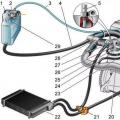
Relay and fuse mounting block for VAZ 2110, VAZ 2111, VAZ 2112 located on the left side of the steering column in the instrument panel ( to reach it, press the latch switch and lower the unit down).
Layout of fuses and relays in the unit (types of units installed on VAZ 2110, VAZ 2111, VAZ 2112 )
Mounting block 2110-3722010
Mounting block 2110-3722010-01
Mounting block 2110-3722010-08
Location of relays and fuses in the mounting block VAZ 2110, VAZ 2111, VAZ 2112:
Fuse decoding:
| room | Current strength, A | Description of fuses |
| F1 | 5 | License plate lamps. Instrument lighting lamps. Control lamp for side light. Trunk lighting lamp. Lamps side light port side |
| F2 | 7,5 | Left headlight (low beam) |
| F3 | 10 | Left headlight (distant sows) |
| F4 | 10 | Right fog lamp |
| F5 | 30 | Door window motors |
| F6 | 15 | Portable lamp (socket) |
| F7 | 20 | Engine cooling fan motor. Sound signal |
| F8 | 20 | Heating element rear window... Relay (contacts) for turning on the heated rear window |
| F9 | 20 | Recirculation valve *. Cleaners and washers windscreen and headlights (wiper fuse). Relay (coil) for turning on the heated rear window |
| F10 | 20 | Spare |
| F11 | 5 | Side light lamps, starboard |
| F12 | 7,5 | Right headlight (low beam) |
| F13 | 10 | Right headlight (far sows). High beam control lamp |
| F14 | 10 | Left fog lamp |
| F15 | 20 | Heated seats. Trunk lock |
| F16 | 10 | Relay-interrupter for direction indicators and alarm (in alarm mode). Warning lamp |
| F17 | 7,5 | Interior lighting lamp. Individual backlight lamp. Ignition switch backlight lamp. Brake lights. Clock (or trip computer) |
| F18 | 25 | Glove box lighting lamp. Heater controller (stove fuse). Cigarette lighter fuse VAZ 2110, VAZ 2111, VAZ 2112. |
| F19 | 10 | Locking door locks. Relay for monitoring the health of brake light and side light. Direction indicators with warning lamps. Light bulbs reverse... Generator excitation winding. Display unit onboard system control *. A combination of devices. Clock (or trip computer) |
| F20 | 7,5 | Rear fog lamp bulbs |
* In the car, in the niche itself dashboard behind the mounting block installed fog lamp fuse.
**Fuse central locking located behind the fuse box in a plastic box.
***Additional relays and fuses located in the passenger compartment on the right of the dashboard behind the side cladding, secured with two screws.
All additional fuses 15 A
The order of the number and color of the wires of the plugs
Scheme mounting block relays and fuses VAZ 2110-11-12
(the outer number in the designation of the wire end is the block number, and the inner number is the conditional number of the plug):
Table of external connections of the mounting block
| Block | № | Colour | Electrical circuits |
| Ш1 | 1 | ZH | Fog lamp (left) |
| 2 | GP | Trunk lock motor, heated seats | |
| 3 | R | Door lock relay | |
| 4 | ABOUT | ||
| 5 | Zhp | Fog lamp relay | |
| 6 | F | Fog lamp (right) | |
| 7 | MS | Power window relay | |
| 8 | - | Reserve | |
| W2 | 1 | - | Reserve |
| 2 | - | Reserve | |
| 3 | - | Reserve | |
| 4 | H | Weight " - " | |
| 5 | Zhp | Dimension (left rear) | |
| 6 | Warhead | ||
| 7 | - | Reserve | |
| 8 | ZH | License plate lights, off lighting devices | |
| 9 | KP | Dimension (right rear) | |
| 10 | TO | Dimension (right) | |
| 11 | WG | Email windshield wiper motor, windshield wiper and washer switch. | |
| 12 | Z | Outdoor light switch | |
| 13 | ABOUT | Fog lamp switch | |
| 14 | State of emergency | ||
| 15 | - | Reserve | |
| 16 | GP | Ignition switch (terminal 15), steering column switch | |
| 17 | R | Windshield wiper and washer switch | |
| 18 | SP | Steering column headlight switch | |
| 19 | - | Reserve | |
| 20 | - | Reserve | |
| 21 | F | Dimension (left) | |
| Ш3 | 1 | Midrange | Low beam (left lamp) |
| 2 | - | Reserve | |
| 3 | FROM | Low beam (right lamp) | |
| 4 | R | Generator (Cl. 30) | |
| 5 | TO | Generator (Cl. 30) | |
| 6 | TO | Generator (Cl. 30) | |
| Ш4 | 1 | PZ | On-board display system |
| 2 | GO | Hazard switch | |
| 3 | IF | Hazard switch | |
| 4 | H | Weight " - " | |
| 5 | PG | Portable lamp plug | |
| 6 | RFP | Heated rear window switch, heated rear window lamp | |
| 7 | - | Reserve | |
| 8 | - | Reserve | |
| 9 | - | Reserve | |
| 10 | ZhZ | ||
| 11 | B | Email windshield wiper motor | |
| 12 | BW | Steering column washer and windscreen wiper switch | |
| 13 | GB | Steering column switch, ignition switch lamp | |
| 14 | BP | Lamps brake lights, clock, interior lamp | |
| 15 | P | Brake lights | |
| 16 | RP | Off stop lights | |
| 17 | ABOUT | Generator (terminal 30) | |
| Ш5 | 1 | ZCH | Main beam (left lamp) |
| 2 | SP | ||
| 3 | D | Heater controller, glove compartment lamp | |
| 4 | Z | High beam (right lamp) | |
| 5 | WG | Windshield wiper motor, SAUO recirculation valve | |
| 6 | PB | Email cooling fan, horn |
Removal and installation of the fuse box.
Wiring diagram of a VAZ-2110 car
| Relay / fuse no. | Decoding |
| 1 | Block headlight |
| 2 | |
| 3 | Fan motor on sensor |
| 4 | Engine cooling fan motor |
| 5 | Sound signal |
| 6 | Generator |
| 7 | Oil level gauge |
| 8 | Control block solenoid valve carburetor |
| 9 | Heater controller |
| 10 | |
| 11 | |
| 12 | Switch |
| 13 | Carburetor limit switch |
| 14 | |
| 15 | Spark plug |
| 16 | Solenoid valve carburetor |
| 17 | Coolant temperature gauge sensor |
| 18 | Ignition distributor sensor |
| 19 | Ignition coil |
| 20 | Starter |
| 21 | Heater fan motor |
| 22 | Additional resistor for the heater motor |
| 23 | Speed \u200b\u200bsensor |
| 24 | Reversing light switch |
| 25 | |
| 26 | Recirculation valve |
| 27 | |
| 28 | Pads for connecting the rear window washer motor |
| 29 | Accumulator battery |
| 30 | Windshield washer motor |
| 31 | |
| 32 | |
| 33 | Windshield wiper motor |
| 34 | Mounting block |
| 35 | Pads for connecting the warning light harness |
| 36 | Outdoor light switch |
| 37 | Instrument cluster |
| 38 | Rear fog light switch |
| 39 | |
| 40 | |
| 41 | Clock |
| 42 | Rear window heating switch |
| 43 | Understeering's shifter |
| 44 | Block for switching wires when installing a headlight unit of another type |
| 45 | Instrument lighting control |
| 46 | Ignition switch |
| 47 | Pads for wiring harness connection for headlight wipers |
| 48 | Portable lamp socket |
| 49 | |
| 50 | Brake light switch |
| 51 | Interior lighting plafond |
| 52 | On-board control system unit |
| 53 | Fuel level indicator sensor |
| 54 | |
| 55 | Driver's seat belt sensor |
| 56 | Cigarette lighter |
| 57 | Ashtray lamp |
| 58 | Glove lamp switch |
| 59 | Connection block on-board computer |
| 60 | Glove compartment lamp |
| 61 | Side direction indicators |
| 62 | |
| 63 | |
| 64 | Parking brake warning lamp switch |
| 65 | Trunk light |
| 66 | |
| 67 | Exterior rear lights |
| 68 | Internal rear lights |
| 69 | License plate lights |
| 70 | Heated rear window |
| 71 | Block for connecting an additional brake light |
* In the instrument panel wiring harness, the second ends of the wires of white, black, orange, white with a red stripe and yellow with a blue stripe are connected together at the same points.
The electrical circuits of the VAZ-2111 and VAZ-2112 cars differ (with the exception of the engine management system) only by adding a cleaner and a tailgate washer.
Wiring diagram of a VAZ-21102 car with a distributed fuel injection system (controller "January-4")
| Relay / fuse no. | Decoding |
| 1 | Block headlight |
| 2 | Front brake pad wear sensors |
| 3 | Sound signal |
| 4 | Cooling fan |
| 5 | Reversing light switch |
| 6 | Accumulator battery |
| 7 | Generator |
| 8 | Oil pressure warning lamp sensor |
| 9 | Oil level gauge |
| 10 | Spark plug |
| 11 | Injectors |
| 12 | Idle speed regulator |
| 13 | Electronic control unit pads |
| 14 | Position sensor throttle |
| 15 | Crankshaft position sensor |
| 16 | Ignition module |
| 17 | Coolant temperature gauge sensor (for instrument cluster) |
| 18 | Starter |
| 19 | Diagnostic pad |
| 20 | Coolant temperature sensor (for engine management system) |
| 21 | Speed \u200b\u200bsensor |
| 22 | Fuel pump relay |
| 23, 35, 39 | Fuses |
| 24 | Electric petrol pump |
| 25 | Micromotor for heater flap drive |
| 26 | Recirculation valve |
| 27 | Heater fan |
| 28 | Windshield washer pump |
| 29 | Washer fluid level sensor |
| 30 | Level sensor brake fluid |
| 31 | Coolant level sensor |
| 32 | Wiper motor |
| 33 | Additional heater fan resistor |
| 34 | Injection Power On Relay |
| 36 | Canister purge valve |
| 37 | Mass air flow sensor |
| 38 | Cooling fan relay |
| 40 | Outdoor light switch |
| 41 | Knock sensor |
| 42 | Oxygen concentration sensor (heated lambda probe) |
| 42* | CO-potentiometer (installed on cars operated on leaded gasoline; in this case, the oxygen concentration sensor is not installed) |
| 43 | Fog light warning lamp |
| 44 | Rear window heating control lamp |
| 45 | Fog light switch |
| 46 | Rear window heating switch |
| 47 | Instrument cluster |
| 48 | Mounting block |
| 49 | Fuel level sensor |
| 50 | Ignition switch |
| 51 | Instrument illumination brightness control |
| 52 | Understeering's shifter |
| 53 | Heater control levers illumination lamp |
| 54 | Hazard switch |
| 55 | Heater electronic control unit |
| 56 | Recirculation valve switch |
| 57 | On-board monitoring system display unit |
| 58 | Side direction indicators |
| 59 | Temperature sensor for heating system |
| 60 | Interior lighting plafond |
| 61 | Front courtesy lamp |
| 62 | Portable lamp socket |
| 63 | Digital Watch |
| 64 | Switches in the front door pillars |
| 65 | Switches in the rear door pillars |
| 66 | Glove compartment lamp |
| 67 | Glove box lighting switch |
| 68 | Cigarette lighter |
| 69 | Ashtray lamp |
| 70 | Brake light switch |
| 71 | Heated rear window |
| 72 | Exterior rear lights |
| 73 | Internal rear lights |
| 74 | License plate lamps |
| 75 | Trunk lamp |
Here are the control diagrams for the VAZ-21120 and 21124 engines. They were installed on the Lada hatchbacks of the 2112 family. on-board network... We are talking about engines containing 16 valves, and the wiring diagram for the VAZ-2112 consists of separate parts: engine control, general scheme... Headlight supply circuit, dimensions, etc. covered in the first chapter.
Wiring diagram of a car in a hatchback body (click on the picture to enlarge)
Legend: 1 - Headlamp block, 2 - Horn, 3 - Main radiator fan, 4 - Starter, 5 - Battery, 6 - Generator, 7 - Gearbox limit switch (reverse), 8 - Actuator in the front passenger door, 9 -, 10 - Starter relay, 11 - Heater fan, 12 - Electric heater partition, 13 - Main pump, 14 - Washer reservoir sensor, 15 - Actuator in the driver's door, 16 - Front passenger window regulator selector, 17 - Button for unlocking the fifth door, 18 - Heater fan resistance unit, 19 - Main wiper motor, 20 - Driver's window regulator selector, 21 - Front passenger window regulator motor, 22 - Central locking, 23 - Outside light switch, 24 - Brake fluid leakage sensor, 25 - Additional pump, 26 - Motor driver's window regulator, 27 - PTF on indicator, 28 - PTF switch, 29 - Dashboard, 30 - Glass heating indicator, 31 - Glass heating switch, 32 - Steering column selector switch, 33 - PTF relay, 34 - Egnition lock, 35 - Main fuse box, 36 - Illumination of heater regulators, 37 - Alarm button, 38 - Heater control controller, 39 - Glove compartment lighting, 40 - Glove compartment lid end switch, 41 - Cigarette lighter, 42 - BSK - display unit, 43 - Backlight ashtrays, 44 - 12V socket, 45 - Switch, 46 - Actuator in the right back door, 47 - Right rear passenger window regulator selector, 48 - Clock, 49 - Right rear passenger window regulator motor, 50 - Brake limit switch (closed - pedal depressed), 51 - Left rear passenger window regulator motor, 52 - Left rear passenger window regulator selector, 53 - Actuator in the left rear door, 54 - Turn signal, 55 - Limit switch hand brake (closed - the handbrake is on), 56 - Rear wiper motor, 57 - Navigator lamp, 58 - Interior light, 59 - Temperature sensor in the heater, 60 - Open front door switch, 61 - Rear door open switch, 62 - Trunk lighting, 63 - Rear optics (on the body), 64 - Rear optics (on the fifth door), 65 - License plate light.
The letters indicate the terminals to which it is connected: A - Front right speaker, B - Radio tape recorder, C - Injector harness, D - Diagnostic connector EUR, D - Front left speaker, E - Heater controller diagnostic connector, F - Rear right speaker, W - Rear left speaker, I - BK connector, K - Glass heater thread, L - Fifth door actuator, M - Additional brake light ...
All door switches remain open when the doors are closed. We provide a wiring diagram for the VAZ-2112 with a description, and information about the limit switches will be useful to signal installers.
Note that starter power can be connected differently. Either the current to terminal 50 is supplied directly from the lock, or through relay 10. The second option (as in the diagram) is less common.
The three relays shown in the diagram are always installed on a block fixed to block 35 from above (see photo).

Main fuse and relay box
Here part 5 is "relay 9" and part 7 is "relay 10".
Window lifters
When the ignition is on, relay 11 closes the contacts. This allows the operation of the power windows controlled by selectors 3, 4, 9 and 10.

Windows do not work without ignition
The diagram does not require any other explanation.
central locking
The diagram shows four actuators, as well as a control unit 3. Actuator 7 is located in the driver's door.

Actuators, central locking unit and one limit switch
It would seem that everything is simple here. But in the description on the VAZ-2112 wiring diagram, the main thing is usually not reported: the white cord is the input for the “Open” command, the brown one is “Close”.
There is a variant of the circuit where only the limit switch is located in module 7 (without an actuator).
Headlights
Relay K4 switches on the low beam lamps, K5 switches on the high beam.

Headlights with single filament lamps
Steering column selector 3 only activates the relayK5. But in the explanation to the wiring diagram on the VAZ-2112 it says that:
- Selector 3 is used to select the "near / far" mode;
- With its help, the high beam lamps are briefly turned on.
It's simple: when switch 4 is in position II, relay K4 closes its contacts. This means that in the " high beam»All lamps work at once.
Dimensions, brake light, backlight
Side lights 1 and 6 are turned on by switch 3. From there, the current flows through the main unit 2, or rather, through the lamp health relay. In the diagram instead of a relayK1 shows jumpers.

Dimensions, room lighting, brake light, instrument lighting
Number plate lighting is lamps 8. They come on regardless of relay actuation. The operation of the reversing lamps also does not depend on the K1 relay, as well as on the switch 3. It is controlled only by the limit switch 10. In a similar way, and (limit switch 11) are switched on.
The brightness of the instrument illumination is regulated by a resistor 9. But there is a nuance: switch 3 must be in position I or II. These positions correspond to the inclusion of indicator 5 (on the tidy).
Turn signals
Turn signal lamps 1, 5 and 6 are activated by switch 7. A relay-breaker K3 is included in the power circuit of these lamps, alternately closing contacts 49a-49 and 49a-31.

The basis of the circuit is a relay-breaker
Without power supply from the ignition switch, the turn signals do not work. There is also an operating mode " Alarm"When:
- Switch 4 is in the up position;
- The current does not come from the ignition switch, but from terminal 3 of the Ш4 connector.
Round trip).
If the contact in the socket of one of the lamps is broken, the response frequency of relay K3 is doubled. In the normal state, it is equal to 1.2-1.9 Hz.
Ignition circuit and engine control systems
We give control schemes for the following internal combustion engines:

| Motor | 21120 (Euro-2) | 21124 (Euro-2) | 21124 (Euro-3) |
|---|---|---|---|
| Injectors | 1 | 2 | 2 |
| Ignition coil | - | 1 | 1 |
| Candles | 2 | - | - |
| Ignition module | 3 | - | - |
| Diagnostic connector | 4 | B | B |
| ECU | 5 | 3 | 3 |
| Taps for tidy | 6 | E | E |
| Ignition relay (6) | 7 | 4 | 4 |
| Ignition circuit fuse (1) | 8 | 5 | 5 |
| Fan relay (4) | 9 | 6 | 6 |
| Fan fuse (2) | 10 | 7 | 7 |
| Fuel pump relay (5) | 11 | 8 | 8 |
| Fuel pump fuse (3) | 12 | 9 | 9 |
| DMRV | 13 | 10 | 10 |
| Rough road sensor | - | - | 11 |
| DPDZ | 14 | 11 | 12 |
| DTOZH | 15 | 12 | 13 |
| IAC | 16 | 17 | 14 |
| Lambda probe main | 17 | 14 | 15 |
| Lambda probe additional | - | - | 16 |
| Knock sensor | 18 | 15 | 18 |
| DPKV | 19 | 16 | 19 |
| Canister purge valve | 20 | 13 | 17 |
| APS block | 21 | 18 | 20 |
| APS indicator | 22 | 19 | 21 |
| Speed \u200b\u200bsensor | 23 | 21 | 23 |
| Fuel pump + level sensor | 24 | 22 | 24 |
| Oil pressure sensor | 25 | 23 | 25 |
| Antifreeze thermometer sensor | 26 | 24 | 26 |
| Oil level gauge | 27 | - | - |
| Phase sensor | 28 | 20 | 22 |
| ABS connector | A | A | A |
| Air conditioner connector | B | IN | IN |
| Fan connector | C | - | - |
| Illumination of the ignition switch (to the blue-white wire) | D + E | - | - |
| Taps for door harness | - | D | D |
| + Battery | F | D | D |
| Weight | G1 + G2 | G1 + G2 | G1 + G2 |
Items in brackets are installed in the optional mounting block.
The principle of operation of the electrical equipment of the VAZ 2110 car is borrowed from other models of the VAZ family. This means that all devices are connected in a single-wire circuit - the car body performs the function of the second (negative) wire. And the negative terminals of consumers and sources of electricity are connected directly to the body.
For ease of maintenance and installation, the electrical wires on the diagrams are made different colors, identical to those laid in the car, so that you can visually determine their purpose.
For brevity, colors are indicated by the first letters of the name:
- Blue - "G";
- Brown - "K";
- Gray - "C";
- White - "B";
- Orange - "O";
- Yellow - "F";
- Black - "H";
- Green - "Z";
- Pink - "P".

For reference: the red wire is traditionally used to supply power from the positive terminal of the generator or battery... Therefore, in all the diagrams that the factory instructions contain, it is indicated by the letter "P".
Fuses
Most of the electrical circuits and all the wiring of the VAZ 2110 to the injector are protected from short circuits by fuses.
However, without protection, the VAZ 2110 is:
- The wire from the battery charge relay to the battery itself,
- VAZ 2110 wiring to the injector, which is responsible for the ignition and engine start circuits;
- Alternator wiring (excluding the field winding, which is activated after turning the key in the ignition switch and starting the engine).

Fuel injection system
If you intend to service the fuel injection system with your own hands, then you must know the principle of its structure and operation.
According to the generally accepted algorithm:
- The amount of fuel required to form a portion of the mixture is regulated by a controller that sends a pulse signal to the injectors;
- The controller itself, before giving a signal, monitors the signals coming from the sensors about iCE operation and its systems;
- Based on these, it calculates the pulse width.

For reference: to understand the principle of operation of an injection motor, it would be nice to watch video materials. From them you will learn that the impulse lasts hundredths of a second, but even a change in such a small value affects the amount of fuel supplied to the cylinders.
In its work, the controller is guided by data from:
- Engine speed sensor (in the diagram - 1);
- Air flow sensor (2);
- Crankshaft position sensor (input 2).
And on their basis, it implements the inherent work algorithm:
- Gives an impulse to turn on fuel injectors (4);
- Gives an impulse to candles (5).
More information in the article
conclusions
Understanding the principles of work injection engine, as well as a short circuit protection circuit for wiring, you can easily detect problem areas and take measures to quickly eliminate them.
Now more and more motorists are striving to replace the carburetor on their VAZ-2110 with an injector, which has a number of significant advantages. It allows the valves in the engine to work much more efficiently, reduces the load on the engine and the average fuel consumption in the vehicle. At the same time, it is simply impossible to install an injector without a circuit, even if you are a professional car service worker.
What is the VAZ-2110 wiring diagram for?
When replacing or repairing an injector with 8 valves, the electrical circuit serves as a kind of guide, with which you can deal with all the nuances in the process of connecting specific wiring parts. In addition, the VAZ-2110 wiring diagram when using an injector with 8 valves allows you to understand the functioning of all wiring devices.
In the diagram, the injector valves are evenly spaced, while the system itself is represented in the form of 2 combined components:
- Fuel distributor;
- Electrical equipment for the ignition control system.
Also on the diagram with 8 and 16 valves, the location of the electronic unit is indicated, with the help of which the work of the above 2 systems is coordinated. Redundant equipment, in turn, protects the wiring from overloads and increases the efficiency of the entire injection system.
Advice: if you are going to repair the injector, be sure to look at the wiring diagram for the VAZ-2106. This will give you the opportunity to replace all defective parts without damaging general work car wiring.
The elements indicated by numbers in the diagram are shown below:
| 1 - block headlight | 35 - instrument lighting switch |
| 2 - front brake pad wear sensors | 36 - ignition switch |
| 3 - reverse light switch | 37 - mounting block |
| 4 - the electric motor of the fan of the engine cooling system | 38 - recirculation valve switch |
| 5 - sound signal | 39 - heater controller |
| 6 - geared motor for locking the lock of the right front door | 40 - alarm switch |
| 7 - relay for turning on power windows | 41 - lamp for lighting the heater control levers |
| 8 - 8 A fuse | 42 - glove box lighting lamp |
| 9 - starter | 43 - glove box lighting switch |
| 10 - accumulator battery | 44 - cigarette lighter |
| 11 - generator | 45 - display unit of the on-board monitoring system |
| 12 - windshield washer motor | 46 - ashtray lighting lamp |
| 13 - washer fluid level sensor | 47 - brake signal switch |
| 14 - geared motor for locking the lock of the left front door | 48 - geared motor for locking the left rear door lock |
| 15 - power window switch for the left front door | 49 - power window switch for the left rear door |
| 16 - coolant level sensor | 50 - motor gearbox of the power window of the left rear door |
| 17 - windshield wiper motor | 51 - socket for a portable lamp |
| 18 - recirculation valve | 52 - clock |
| 19 - micromotor drive of the heater flap | 53 - motor gearbox of the power window of the right rear door |
| 20 - heater electric motor | 54 - power window switch for the right rear door |
| 21 - trunk lock switch | 55 - geared motor for locking the lock of the right rear door |
| 22 - power window switch for the right front door | 56 - side direction indicator |
| 23 - motor gearbox of the power window of the right front door | 57 - parking brake warning lamp switch |
| 24 - control unit for door lock system | 58 - driver's seat belt sensor |
| 25 - additional resistor of the heater electric motor | 59 - directional light shade |
| 26 - brake fluid level sensor | 60 - interior lighting plafond |
| 27 - motor gearbox of the left front door power window | 61 - interior temperature sensor |
| 28 - outdoor lighting switch | 62 - switch in the front door pillar |
| 29 - instrument cluster | 63 - switch in the rear door pillar |
| 30 - switch for rear fog light | 64 - external rear light |
| 31 – control lamp fog light | 65 - internal rear light |
| 32 - control lamp for heating the rear window | 66 - license plate lights |
| 33 - rear window heating switch | 67 - trunk lighting |
| 34 - Understeering's shifter |
The diagram of electrical wires and fuses gives an understanding of the entire operation of the injection system, and also shows the specific position of each of the elements. The following elements are located on it:
- Central nozzle. Serves as a distributor of fuel supply to the system. There is also a special type fuel regulator, which works as a sensor and monitors that the fuel supply indicators do not go beyond the normalized limits.
- Membrane regulator. Monitors fuel pressure in the ignition system and removes excess fuel back into the tank body.
Advice: make sure that the pressure in the fuel supply system does not exceed 300 MPa. Otherwise, you will see the corresponding icon on the instrument panel and you will most likely have to replace the coolant with the VAZ-2110.
- Design check valve... It regulates the position of the cross diaphragm, which is subjected to constant pressure from three sides: on the one hand, the pressure of the fuel being poured, on the other hand, the tangential load from the suction volumes of air, and on the third side, the tension from the spring fixed to the valve.
How to regulate the fuel supply process using the electrical circuit?
According to the scheme described above, the fuel regulation in the car is performed. Moreover, it depends not only on the load of the valves in the engine, but also on the corresponding position relative to the throttle valve. Using the scheme electrical wiring and valves, it is possible to understand which of the relay or fuses is working with a malfunction, and replace it in time. In this case, one of the main roles in the supply of fuel is performed by electrical equipment (controllers) that regulates the operation of the injector.
How does the controller monitor the injector operation?
When determining the specific position and opening time of the nozzle structure, the specific volume of fuel entering the VAZ-2110 cylinder valves is determined. At the same time, thanks to special sensors installed on the motor, the on-board computer records specific values \u200b\u200band transmits them to the controller.
Subsequently, the controller, based on the information emanating from the on-board computer, makes a decision on the position and duration of the injector flap opening. In the event of a controller malfunction, the injectors will not be adjusted correctly, and the engine may stall on the move.
Advice: when the engine is started, the injector controller operates in asynchronous mode until the engine reaches a certain number of revolutions. That is why, after replacing the silent blocks of the front levers with a VAZ-2110, you should warm up the car for 10-15 minutes.
How does the malfunction of the electronic control unit affect the operation of the injector?
Block electronic control the VAZ-2110 machine consists of 3 high-precision components:
- ROM - data storage devices (memory);
- EPROM - a device for transmitting dynamic data;
- RAM - block regulating memory.
Advice: the whole complex of the presented elements will function only if there is voltage in the circuit. If there is no voltage in the wiring, then it is necessary to troubleshoot the fuse box on the VAZ-2110.
In this way, the electronic unit control acts as a kind of microprocessor, which is responsible for the operation of the entire fuel supply system. If it breaks down, even an experienced motorist cannot repair it with his own hands. For repairs, contact the nearest car service and wait for the result. If the unit does not have any faults, the breakdown must be looked for among the injector and controller elements.
Advice: in the center of the dashboard on a VAZ-2110 car, a signal light called "CHECK ENGINE" may light up. In this case, the problem is definitely not in the control unit, the problem is related to a malfunction of the controller.
So, if you notice that your engine has begun to stall constantly while driving and spends more fuel at the same distance as before, refer to the injector diagram for the VAZ-2110. With a little understanding of each of the elements, you can quickly find defective item and replace it.