Diagnostics and repair: CAN - Tire
21.02.2006
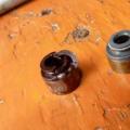
This is what looks like (basically) the same "tireCAN ", with which recently we will have to face more and more often:
photo 1.
This ordinary two-wire cable called twisted pair .
In this photo 1 shows the wires of CAN HIGH and CAN LOW power aggregate.
On these wires, data exchanges between control blocks, they can carry information about the velocity of the vehicle, rotation speed crankshaft, ignition advance angle and so on.
Please note that one of the wires is additionally marked with a black stripe. It is thus noted and visually determined by the wireCAN HIGH (orange-black).
Color wireCAN-LOW. - Orange-brown.
For the main color of the tireCAN Adopted orange color.
In the drawings and drawings, it is customary to depict the colors of the tire wires.CAN Other flowers, namely:

photo 2.
CAN-HIGH. - Yellow color
CAN-LOW. - Green
There are a few varieties of tires.CAN defined by the functions performed by them:
CAN Tire Power Unit(Quick channel) .
It allows Transfer information at speeds) 500 kbps and serves to communicate between control blocks (Engine - Transmission)
Bus CAN system "Comfort"(Slow Canal) .
It allows Transmit information at a speed of 100 kbps and serves to communicate between the control blocks that are included in the Comfort system.
CAN data bus information and command system(Slow channel), allowing to transmit data at 100 kbit / s. Provides communication Between various servicing systems (for example, telephone and navigation systems).
New car models are increasingly similar to airplanes - in terms of the number of stated features for safety, comfort and environmental friendliness. Control blocks are becoming more and more and "pull" from each bunch of wires - unrealistic.
Therefore, except for the tireCAN There are already other tires that have called titles:
- LIN bus (single-wire bus)
- Tire MOST (fiber-fiber tire)
- Bluetooth Wireless Tire
But we will not "break out the thought of the tree", will sharpen our attention so far on one particular tire:CAN (according to the views of the corporationBosch).
On the example of the CAN bus The power unit can be seen in the signal form:

Photo 3.
When on High Bus CAN Dominant state, the voltage of the wire rises to 3.5 volts.
In a recessive state, the voltage on both wires is 2.5 volts.
When on the WireLow. Dominant state, the voltage drops to 1.5 volts.
("Dominant" is a phenomenon dominant, dominant or dominant in any sphere, from dictionaries).
To increase the reliability of data transfer, busCAN A differential method of transmitting signals on two wires having a name is applied.Twisted Pair. . And wires that form this pair are calledCAN HIGH and CAN LOW .
In the initial state of the tire on both wires is supported constant pressure On a certain (basic) level. For tireCAN Power unit It approximately equals 2.5 volts.
Such an initial state is called the "rest state" or "recessive".
How signals are transmitted and convertedCAN Tire?
Each of the control blocks is connected toCAN The bus through a separate device called the transceiver in which there is a signal receiver, which is a differential amplifier installed at the signals input:

photo 4.
Entering on wiresHIGH and LOW. The signals enter the differential amplifier are processed and entered on the input of the control unit.
These signals represent the voltage at the output of the differential amplifier.
Differential amplifier forms this output voltage as a difference between voltages on High and Low wires tires Can..
Thus, the influence of the magnitude of the base voltage is eliminated (in the CAN bus of the power unit, it is 2.5 V) or any voltage caused by, for example, by external interference.
By the way, about interference. As they say, "tireCAN Pretty resistant to interference, so it found such widespread use. "
Let's try to deal with it.
Wires of tires CAN. The power unit is located in motor compartment And they can influence interference of various orders, for example, interference from the ignition system.
Since the tire can It consists of two wires that are twisted with each other, the interference simultaneously affects two wires:

From the above figure, it can be seen that it happens next: in the differential amplifier, the voltage on the LOW wire (1.5 V - "Pp. ") Removed from the voltage
on HIGH (3.5 V - "Pp. ") There is no interference in the processed signal ("PP "- interference).

Note: By the presence of time, the article may have a continuation - much still remains "for the scenes".
Kucher V.P.
© Legion Autodata
You may also be interested in:
In order to streamline the work of all controllers that facilitate control and increase driving control, the CAN bus is used. You can connect such a device to the machine signaling with your own hands.
[Hide]
What is a CAN bus and the principle of her work
Kan bus is a network of controllers. The device is used to combine all car control modules into one work network with a common wire. This device consists of one pair of cables, which is called CAN. Information transmitted through the channels from one module to another is sent in the encoded form.
Connection diagram of devices to the CAN bus in Mercedes
What functions can perform a CAN bus:
- connecting to the automotive on-board network of any devices and devices;
- simplifying the algorithm for connecting and functioning the auxiliary systems of the machine;
- the unit can simultaneously receive and transmit digital data from different sources;
- the use of the tire reduces the effect of external electromagnetic fields on the functioning of the main and auxiliary systems of the machine;
- CAN bus allows you to speed up the procedure for transferring information to specific devices and knots of the car.
This system works in several modes:
- Background. All devices are disabled, but power is supplied to the bus. The magnitude of the voltage is too small, so the bus battery can not be discharged.
- Run mode. When the motorist inserts the key into the lock and turns it or hits the start button, the device is activated. The power stabilization option is included, which is fed to controllers and sensors.
- Active mode. In this case, between all controllers and sensors, data exchange occurs. When working in active mode, the power consumption parameter can be increased to 85 mA.
- Fucking or shutdown mode. If the power unit is silent, Kan controllers cease to function. When you turn on the fallback mode, all machine nodes are disconnected from the on-board network.
Channel Vialon Drying in his video told about the cat-bus and what to know about its operation.
Pros and cons
What advantages have a can-bus:
- Easy installation of the device in the car. The owner of the car does not have to spend money on installation, since you can perform this task yourself.
- The speed of the device. The device allows you to quickly share information between systems.
- Resistance to interference.
- All tires have a multi-level control system. Its use makes it possible to prevent errors when transmitting and receiving data.
- In the process of operation, the tire automatically scatches the speed on different channels. This allows you to provide optimal operation of all systems.
- High security device, if necessary, the system blocks unauthorized access.
- Large selection of devices different types from different manufacturers. You can choose an option designed for a specific car model.
What disadvantages are characteristic of the device:
- There are restrictions on the volume of transmitted data. IN modern cars Many electronic devices are used. Their large amount leads to the high load of the information transfer channel. This becomes the reason for increasing the response time.
- Most of the data from the bus have a specific intended purpose. The useful information is given a small part of the traffic.
- When using the top-level protocol, the car owner may face the problem of lack of standardization.
Types and labeling
The most popular tire type are devices developed by Robert Bashes. The device can function sequentially, that is, the signal is transmitted beyond the signal. Such devices are called Serial Bus. You can find on sale and parallel parallel bus tires. These data transmission is carried out in several communication channels.
On varieties, principle of action, as well as the possibilities of the Can-bus, you can learn from the video shot by the Diyordie Channel.
With considering different types Identifiers You can select multiple types of devices:
- Kang2, 0a asset. So label devices that support the 11-bit data exchange format. These nodes do not indicate errors on the pulses of the 29-bit node.
- Kang2, 0V asset. The devices operating in a 11-bit format are labeled. The main difference is that when the identifier is detected by 29 bits in the system, they will transmit an error message to the control module.
We must take into account that in modern machines Such types of devices do not apply. This is due to the fact that the operation of the system should be agreed and logical. And in this case, it can function at several pulse transmission rates - by 125 or 250 kbps. More low speed Used to control additional devices, such as lighting devices in the cabin, power windows, wipers, etc. High speed Need to ensure the working state of the transmission, the power unit, aBS systems etc.
Variety of tire functions
Consider what functions have different devices.
Motor Device
When the device is connected, a quick data channel is provided, according to which the information is distributed at a speed of 500 kbps. The main purpose of the tire is to synchronize the operation of the control module, for example, gearboxes and motor.
Comfort type device
The data transfer rate for this channel is lower and is 100 kbps. The function of such a tire is to connect all devices relating to this class.
Informational Command Device
Data transfer rate is the same as in the case of comfort type devices. The main task of the tire is to ensure communication between the serviced nodes, for example, the mobile device and the navigation system.
Tires from different manufacturers are shown in the photo.
1. Device for car DVS 2. Interface analyzer
Can there be problems in the work of CAN-tires?
IN modern car digital tire Used constantly. It works simultaneously with several systems, and information is constantly transmitted over its communication channels. Over time, malfunctions may experience. As a result, the data analyzer will function incorrectly. If troubleshooting is detected, the car owner must find the cause.
For what reasons failures in operation arise:
- damage or breaking the electrical caps of the device;
- there was a closure in the system on the battery or mass;
- could close the CAN-HAY or CAN-LOU system;
- damage to rubberized jumpers occurred;
- the discharge of the battery or the reduction of voltage in the onboard network caused by the incorrect operation of the generator device;
- there was a breakdown of the ignition coil.
When searching for reasons, take into account that the malfunction can be in incorrect operation of the auxiliary devices installed additionally. For example, the reason may be improperly functioning. anti-theft system, controllers and devices.
About repair CAN-tires dashboard In the car Ford Focus 2, you can learn from the video taken by the BROKK - Video Corporation.
The process of finding a fault is carried out like this:
- First, the car owner is diagnosed with the system status. It is advisable to implement a computer check to identify all problems.
- At the next stage, the voltage and resistance of the electrical circuits is diagnosed.
- If everything is in order, the resistance parameter of rubberized jumpers is checked.
Diagnostics of the functionality of the CAN-Tire requires certain skills and experience, so the troubleshooting procedure is better to entrust to those skilled in the art.
How to connect alarm to a can-bus
To connect the can-bus with your own hands to car alarm with a car with autorun or without it, you need to know where the anti-theft control unit is located. If the alarm installation was carried out independently, the search process will not cause complexity of the car owner. The control module is usually placed under the dashboard in the steering wheel area or behind the control panel.
How to make a connection procedure:
- The anti-theft system must be installed and connected to all nodes and elements.
- Find a thick orange cable, it connects to a digital bus.
- The adapter of the anti-theft system is connected to the contact of the tire found.
- Installation of the device is performed in a safe and convenient location, the device is fixed. It is necessary to exhibit all the electrical chains to prevent them in eradicate and leaks. Diagnosis is performed by the correct task.
- At the final stage, all channels are configured to ensure the operating state of the system. You must also specify a functional range of device.
This guide is used to verify the recognition of the high-level CAN signal and the low CAN level to connect to the bus.
Used cable
Multifunctional cableInstructions for verification
- Voltage check (oscilloscope): Ankb must be connected to voltage and ignition is connected.
- Resistance Measurement: When measuring the resistance, it is necessary that the measured object be in front of the measurement is shown in a de-energized state. To do this, disconnect accumulator battery. Wait 3 minutes while all the capacitors are discharged.
CAN bus information
CAN tire (Controller Area Network) is a consistent communication bus system and differs in the following features:
- the signal propagation occurs in both directions.
- Each message takes all tire subscribers. Each subscriber of the tire itself decides whether it will use the message
- Additional tire subscribers are added by simply parallel inclusion.
- The bus system forms a system with a specifying device. Each tire subscriber can be a specifying or executive device, depending on whether it is connected as a transmitter or receiver.
- A two-wire connection is used as a means of transmission. Wire Designations: Low CAN Level and High CAN.
- As a rule, each tire subscriber can communicate over the bus with all other tire subscribers. Data exchange over bus is regulated by the access rules. The main difference between the K-CAN data transmission bus (CAN Body Bus), the PT-CAN bus (motor and transmission bus) and the F-CAN bus (CAN tire of the chassis) is:
- K-CAN: Data transfer rate OK. 100 kbps. Possible single-wire mode.
- PT-CAN: Data transfer rate OK. 500 kbps. Single-wire mode is not possible.
- F-CAN: Data transfer rate OK. 500 kbps. Single-wire mode is not possible.
Specifying device: The specifying device is an active partner due to the communication initiative. The specifying device has priority and manages the connection. It can send a tire to the passive subscriber (executive device) of the tire system and after the request to receive its messages.
Executive device: The actuator is a passive participant of communication. It receives the command to receive and transmit data.
System with a specifying device: In a system with a master device, communication participants may at a certain point in time to assume the role of a specifying or executive device.
Oscilloscope of K-CAN, PT-CAN, F-CAN
For greater clarity, whether the CAN bus works flawlessly, it is necessary to observe the connection on the bus. There is no need to analyze individual bits, but you only need to make sure that the CAN bus works. Oscilloscope shows: "CAN bus obviously works without disturbances."
K-CAN:
Low CAN level relative to mass: U min \u003d 1 V and U Max \u003d 5 V
High level CAN relative to mass: U min \u003d 0 V and U Max \u003d 4 in
Settings oscilloscope for measuring on k-CAN bus:
Fig. 1: Measurement K-CAN: CH1 Low CAN, CH2 High CAN Level
When measuring with a voltage oscilloscope between the low-level wire CAN (or high CAN-HIGH) and the mass is obtained by a rectangular signal within the voltage:
PT-CAN and F-CAN
Low CAN level relative to mass: U min \u003d 1.5 V and U max \u003d 2.5 V
High CAN level relative to mass: U min \u003d 2.5 V and U max \u003d 3.5 V
These values \u200b\u200bare approximate and may differ, depending on the load of the tire, by a value of up to 100 mV.
Settings of the oscilloscope for measurement on the PT-CAN bus (or F-CAN):
Figure 2: Measuring PT-CAN: CH1 Low CAN, CH2 High CAN Level
The procedure for measuring resistance with matching resistance K-CAN, PT-CAN and F-CAN
Resistance measurement test process:- CAN bus must be de-energized
- Other measuring instruments should not be connected (parallel inclusion measuring instruments)
- Measurement is performed between Low CAN wires and high CAN levels
- Actual values \u200b\u200bmay differ from the specified values \u200b\u200bfor several Ohm.
K-Can.
On the K-CAN bus, it is impossible to carry out a separate measurement of resistance, as the resistance varies depending on the inclusion logic of the ECU!
PT-CAN, F-CAN
To prevent the signal reflect, the two CAN bus subscribers (with maximum removal in the PT-CAN network) are loaded with 120 ohm resistance. Both loading resistances are included in parallel and form an equivalent resistance of 60 ohms. When the supply voltage is disconnected, this equivalent resistance can be measured between data lines. In addition, it is possible to measure individual resistance separately.
Instructions for measuring with resistance of 60 ohms: Disconnect the easily accessible ECU from the tire. Measure the resistance on the connector between the wires of the CAN low and high levels.
Note!
Not on all cars there is a matching resistance on the CAN bus. The presence of built-in matching resistance on the connected car can be checked according to the corresponding electrical circuit.
CAN bus does not work
If the K-CAN or PT-CAN data transmission bus does not work, then may have a CAN CAN high or a CAN wire closer low levels. Or faulty ECU.
- In turn, disconnect the CAN tire subscribers until the block is found, which is the cause of the fault (\u003d ECU X).
- Check the wires to the ECU X in the absence of a short circuit or cliff.
- If possible, check the ECU X.
- Such a sequence of actions leads to success only if the short circuit has a conducted wire from the ECU to the CAN bus. If the wire in the CAN bus itself has a short circuit, then you need to check the wiring harness.
We reserve the right to typos, semantic errors and technical changes.
CAN bus is a device that facilitates the control of the machine by exchanging information with other systems of the car. Data transfer from one automotive block It is carried out on special channels using encryption.
[Hide]
What is a CAN bus
The electronic cat-interface in the car is a network of controllers used to combine all control modules into a single system.
This interface is a block with which the blocks can be connected by wires:
- anti-theft complex equipped with autorun function or without it;
- machine motor control systems;
- anti-lock assembly;
- security systems, in particular, pillows;
- control automatic box gears;
- control panel, etc.
Device and where the tire is
Constructively CAN bus is a block made in a plastic case or a connector for connecting cables. The digital interface consists of several conductors called CAN. One cable is used to connect blocks and devices.
Mounting the device depends on the model vehicle. Usually this nuance is indicated in the service manual. The San-tire is installed in the car, under the control panel, sometimes can be located in the rotor space.
How does it work?
Principle of operation automatic system It is to transmit encoded messages. Each has a special identifier, which is unique. For example, "The temperature of the power unit is 100 degrees" or "Machine speed of 60 km / h". When transmitting messages, all electronic modules will receive appropriate information that is checked by identifiers. When the data transmitted between devices relates to a specific block, they are processed if not - ignored.
The CAN-bus identifier length can be 11 or 29 bits.
Each information transmitter simultaneously reads the data transmitted to the interface. The device with a lower priority must release the bus, since the dominant level with a high indicator distorts its transmission. At the same time, the package with an increased value remains untouched. The transmitter who lost the connection, after a certain time it restores it.
Interface connected to the signal or module automatic launchmay operate in different modes:
- The background, which is called sleeping or autonomous. When it is running, all major machine systems are disabled. But at the same time, the digital interface enters power from the power grid. The magnitude of the voltage is minimal, which allows you to prevent the battery discharge.
- Run or awakening mode. It begins to function when the driver inserts the key into the lock and turns it to activate the ignition. If the machine is equipped with a start / stop button, this happens when it is pressed. The voltage stabilization option is activated. Power is supplied to controllers and sensors.
- Active. When this mode is activated, the data exchange procedure is carried out between regulators and executive devices. The voltage parameter in the chain increases, since the interface can consume up to 85 mA.
- Deactivation or falling asleep. When the power unit stops, all systems and nodes connected to the CAN bus are stopped functioning. Their deactivation from the electric network of the vehicle is performed.
Characteristics
Technical properties of the digital interface:
- the total value of the information transfer rate is about 1 MB / s;
- when sending data between control blocks various systems This indicator decreases to 500 kb / s;
- information transfer rate in the Comfort type interface is always 100 kb / s.
Channel "Electrical Equipment and Electronics for Programmers" spoke about the principle of sending batch data, as well as on the characteristics of digital adapters.
CAN-tire species
Conditionally CAN bus can be divided into two types among themselves in accordance with the Identifiers used:
- Kang2, 0a. Digital devices are so labeled, which can function in a 11-bit data exchange format. This type of interfaces by definition cannot identify errors to signals from modules operating from 29 bits.
- Kang2, 0B. Digital interfaces operating in a 11-bit format are labeled. But the key feature is that error data will be transmitted to microprocessor devices if the identifier is detected by 29 bits.
CAN bus can be divided into three categories in accordance with the view:
- For the power unit of the car. If you connect such a type of interface to it, this will ensure a quick link between the control systems on the additional channel. The purpose of the tire is to synchronize the operation of the motor ECU with other nodes. For example, gearbox, anti-lock system etc.
- Comfort type devices. This kind of digital interfaces is used to connect all systems of this category. For example, electronic mirrors adjustment, seats heating, etc.
- Information and command interfaces. Have a similar information transfer rate. Used to ensure high-quality communication between the nodes needed to serve the vehicle. For example, between electronic block Department I. navigation system or smartphone.
On the principle of action, as well as the varieties of digital interfaces, the channel "Electrical Equipment and Electronics for Programmers" told.
Instructions for connecting alarm for the Can-bus
When installing the anti-theft system, a simple version of its compounds with onboard network - to tie security installation With a digital interface. But this method is possible if there is a can-bus in the car.
To install a car alarm and connect it to the CAN interface, you need to know the installation location of the system control unit.
If the signaling was put by experts, then you need to ask for help with this question for a hundred. Usually the device is located behind the car dashboard or under it. Sometimes the installers put a microprocessor module in the free space for the glove compartment or car radio.
What do you need?
To fulfill the task, you will need:
- multimeter;
- stationery knife;
- insulating tape;
- screwdriver.
Step-by-step action
Connection procedure anti-theft Installation The CAN bus is carried out like this:
- First you need to make sure that all items security complex Installed and work. We are talking about a microprocessor unit, antenna module, service button, siren, as well as end switches. If the alarm has an autorun option, you need to make sure that this device is installed correctly. All elements of the anti-theft installation are connected to the microprocessor unit.
- The search for the main conductor going to the CAN bus is performed. It is thicker and its insulation is usually painted in orange.
- The main unit of car alarm is connected to this contact. To perform the task, use the digital interface connector.
- Installation of the control unit security systemif it was not installed. It should be placed in a dry and inaccessible to an extraneous eye. After installation, the device must be qualitatively fixed, otherwise in the process of movement, the vibration will be negative. As a result, this will lead to a quick breakage of the module.
- The location of the conductors connect is carefully insulated, the use of shrink tubes is allowed. It is recommended to optimize the wires of the wire. This will increase their resource operation and prevent erase of the insulating layer. When the connection is executed, checks. If there are problems in transmitting batch data, using a multimeter should be diagnosed with the integrity of the electrical caps.
- At the final stage, the configuration of all communication channels is performed, including additional if they are. This will ensure uninterrupted work Security system. For configuration used service bookincluded in the configuration package.
The Sigmax69 user spoke about connecting a security complex with a digital interface using the example of the car Hyundai Solaris 2017.
Fault
Since the CAN interface is tied with many car systems, with a breakdown or incorrect operation of one of the nodes, malfunctions may appear. Their presence will affect the functioning of the main aggregates.
Signs and reasons
This "symptoms" can report on the appearance of faults:
- on the dashboard, there are several icons at the same time without reason - airbags, steering, pressure in the lubrication system, etc.;
- appeared light check. Indicator Engine;
- in the control panel there is no information on the temperature of the power unit, the level of fuel in the tank, velocity, etc.
The reasons why malfunctions may occur in the work of the CAN interface:
- wiring breaks in one of the systems or damage to electrolytes;
- short circuit in the work of the battery or land;
- damage to rubber jumpers on the connector;
- the oxidation of the contacts, as a result of which the transmission of the signal between systems is broken;
- the discharge of the car's battery or the drop in the voltage in the power supply, which is associated with the incorrect functioning of the generator installation;
- closure of CAN-HIGH systems or CAN-Low;
- the appearance of faults in the ignition coil.
Details of the digital interface and testing using a computer told the KV Avtoservis channel.
Diagnostics
To determine the cause of troubleshooting, a tester will be required, the use of a multimeter is recommended.
Check process:
- Diagnostics begins with the search for the conductor twisted the CAN-Tire pair. The cable has a black or orange-gray isolation. The first is the dominant level, and the second is secondary.
- Using a multimeter, a voltage value is checked on the contact elements. When executing the task, the ignition must be included. Testing procedure will allow you to identify the voltage in the range from 0 to 11 volts. In practice, this is usually 4.5 V.
- Ignition shutdown. From the battery, a conductor with a negative contact is disconnected, a pre-wrench must be loosen the clamp.
- The resistance parameter between the conductors is measured. You can find out about the closure of contacts if this value is striving for zero. When the diagnosis showed that the resistance is infinite, then the electrolene has a break. The problem can be directly in contact. It is required to check the connector and all the wires in more detail.
- In practice, the closure usually occurs due to breakage of control devices. To search for the failed module, it should be turned off from the power to each block and perform the validation of the resistance.
The user of Filat Gorodnikov spoke about the diagnosis of can-bus using an oscilloscope.
How to make the analyzer with your own hands?
Alone to complete the assembly this device Only a professional in the field of electronics and electrical engineering will be able.
The main nuances of the procedure:
- In accordance with the diagram on the first photo in the gallery you need to purchase all items for the development of the analyzer. The components are signed on it. A board with the STM32F103C8T6 controller will be required. It will take the electrical process of the stabilized regulatory device and the CAN transceiver MSR2551.
- If necessary, bluetooth module is added to the analyzer. This will allow you to record basic information on the mobile device when operating.
- Programming procedure is performed using any utility. It is recommended to apply Chankhar or Arduino programs. The first option is more functional and has the option to filter batch data.
- To make the firmware, you will need a USB-TTL conversion device, it will be needed for debugging. Simple version - Application of ST-Link second version.
- By downloading the program to the computer, the main file of the EX format must be flashing into the controller using the programmer. After executing the task, the jumper of the bootloader is put, and the manufactured device is connected to the PC via USB output.
- You can pour the firmware to the analyzer using software MphidFlash.
- When the software update is completed, you need to disconnect the wire and dismantle the jumper. Drivers are installed. If the device is assembled correctly, then it will be defined as a COM port on the computer, it can be viewed in the task manager.
Photo Gallery
CAN-Analyzer Development Scheme The main board for assembling the device
Pluses and cons CAN-tires
The advantages that the digital interface has the advantages:
- Speed. The device can quickly exchange batch data between different systems.
- High resistance to electromagnetic interference.
- All digital interfaces have a multi-level control system. Due to this, you can prevent errors when transmitting information and its reception.
- When working, the bus itself spreads speed through the channels in automatic mode. This ensures efficient work. electronic systems vehicle.
- The digital interface is safe. If someone tries to receive illegal access to electronic nodes and car systems, the tire will automatically block this attempt.
- The presence of a digital interface allows you to simplify the installation of the security system on the machine with minimal intervention in the standard onboard network.
CAN-bus possesses:
- Some interfaces have limitations in terms of information that can be transmitted. This disadvantage will be weighty for a modern car, "stuffing" electronics. When adding additional devices to the bus placed higher load. Because of this, the response time is reduced.
- All batch data that is transmitted over the bus have a specific purpose. For useful information The minimum part of the traffic is given.
- If an increased level protocol is applied, it will be the absence of standardization.
Video "Repair of the CAN interface with your own hands"
User Roman Brock spoke about the procedure for restoring the dashboard bus in the car Ford Focus 2 restyling.