Modern engines internal combustion consist of a large number of parts. Among them, you can find completely different elements that have completely different, but very useful purposes for the engine. Such a small detail as a pump-injector is no exception. In this article we will analyze the device, the principle of operation and repair of the pump-injector.
The device and the principle of operation of the pump-injector
The nozzle is a metal tube with a special section for spraying fuel mixture... For the first time to this day, such a device is used on diesel engines, where such important parameters as engine efficiency are important, low level its noise and low toxicity exhaust gases.
The nozzle pump is installed above each cylinder and has the same structure. It usually includes: a check piston, a special plunger, a spray needle, a check and control valve, and a spray spring.
A plunger is a part that creates a certain pressure inside the nozzle. Pumping occurs during the translational movement of the plunger. For this, there are special cams on the camshaft, which at certain points in time act on the plunger and activate it.
The control valve opens in line with the movement of the plunger and allows fuel to flow into the combustion chamber. The design of the valve is selected in such a way that the diesel fuel must be supplied in atomized form. So it burns more efficiently and more economically. According to the principle of operation, the control valves can be divided into electromagnetic and piezoelectric. Piezoelectric valves are the most effective, as they work quickly and do not allow the formation of excess fuel, as well as its starvation in certain areas of the injection system. The main element of any control valve is its needle, which is precisely responsible for the speed of the system.

The spray spring is installed to ensure a snug fit of the needle. The spring force is usually supplemented by the fuel pressure created in the fuel pump high pressure... For this, a special locking piston is installed on the opposite side of the spring, which presses on it under the influence of fuel.
Control of any pump-injector is provided by means of. The ECU receives various readings from all sensors, analyzes them and, based on the data received, opens or closes the injectors at certain points in time.
Principle of operation:

- Pre-injection... At this moment, a special timing cam acts on the plunger, forcing it to move downward. The fuel / air mixture flows into the injector channels and the check valve closes. The plunger creates a pressure of 13 MPa, and at this moment the nozzle control valve is activated, which passes the mixture under pressure into the combustion chamber. At the last moment, the inlet valve opens and a new portion of fuel enters the injector channels. At the same time, the fuel pressure inside the cell decreases.
- Main injection... At this stage, the plunger goes down again, the control valve closes, but the pressure in the nozzle is already at 30 MPa. This time, the fuel is supplied under high pressure, which ensures its efficient compression and combustion in the working chamber. Each subsequent compression process is accompanied by an increase in pressure inside the nozzle. The maximum value is 220 MPa. The end of this stage takes place in the same way as with the preliminary injection of fuel.
- Additional injection... It consists in cleaning all the elements of the nozzle from traces of soot and soot. The additional injection is carried out immediately after the main injection. All injection actions are carried out in the same way as in the main stage. In another way, this phenomenon is also called double fuel injection.
Video - How to determine which pump injector does not work or knocks
How to repair pump nozzles with your own hands
Of course, replacing a faulty injector will be much more correct. However, if we take into account today's prices for auto parts, then the thought involuntarily arises of why not repair the old one, because it is cheaper. In fact, an injector repair kit costs a lot less than a new one and is therefore much more profitable.

The malfunction of the injectors usually consists in their clogging or deterioration of the sealing properties of the internal rubber gaskets. At the same time, the engine starts to work unstably and does not develop the rated power, and the fuel consumption increases markedly.
When selecting a repair kit, it is important to respect the make and model. In order not to be mistaken, we recommend that you remove the old one and take it with you to the auto parts store. The consultants will select for you the kit that you need for the repair. If you install gaskets designed for a different model of injector, then most likely the injector will not work at all correctly. Although, in most cases, they have completely different sizes of gaskets, which will make the repair itself problematic, rather than the further operation of such an element.
To repair an old injector, it must be dismantled. To do this, you first need to relieve the pressure in the fuel system. This is necessary in order not to get dirty with fuel and not get a powerful jet right in the face.
After that, the metal fastening of the tube to the nozzle is unscrewed and it is turned inside out. Disassemble the element and carefully note the location and assembly order of the parts. This is necessary for the subsequent assembly, so that there is no such thing as the appearance of "extra" parts. Now clean the metal parts in the event that they are clogged, replace the rubber seals and other parts that are in repair kit nozzles. After that, reassemble the part in the reverse order of disassembly.
Screw in the injector and connect it to the fuel system. Since the pressure has been reduced, it is necessary to unscrew the manual fuel priming knob and re-pressurize the system. It should be rocked until the handle is tight. After that, wrap it up again and you can start starting the engine.
Video - Repair of pump injectors BOSCH
This completes the pump - injector repair. It should be reminded once again that this procedure not difficult at all, and most importantly - it will require the least cost from you. After all, prolonging the life of an old nozzle is much cheaper than installing a new one.
The use of such a system makes it possible to increase engine power, reduce fuel costs and toxicity, and noise levels.
In the injection system of this type a single central unit - the pump-injector - is responsible for fuel supply and distribution. Moreover, each cylinder is equipped with its own nozzle.

The system is driven by a camshaft equipped with special cams that act through a rocker arm on the unit injector, ensuring its operation.
How the unit injector system works
The pump-injector system includes such elements as: plunger, shut-off piston, control and non-return valves, spray needle.

The plunger is designed to create working pressure inside the nozzle. In this case, the movement of the plunger of a translational nature is provided by the camshaft cams, and the return movement is provided by a spring.
The main function of the control valve is fuel injection, or rather, injection control. In such systems, two types of valves can be used - electromagnetic and piezoelectric.
A valve based on a piezoelectric element is more advanced due to its high speed. The main structural element of the control valve is its needle.
The nozzle spring is required to ensure that the nozzle needle fits securely in the seat. The spring force is supplemented by the fuel pressure force, and this is all done with the help of a check piston mounted on one side of the spring and check valvelocated on the opposite side of the spring.
Spray needle for direct injection diesel fuel into the combustion chamber of the engine.
The unit injectors are controlled by the engine control unit, which, based on the data obtained from the sensors, controls the operation of the unit injector valve.
How the unit injector system works
Efficient receipt and distribution of fuel assemblies in the unit-injector system occurs in three stages - preliminary, main and additional fuel injection.
Pre-injection
The preliminary injection stage is designed to ensure smooth combustion of fuel assemblies at the main injection stage. The main injection stage, in turn, ensures uninterrupted supply of the fuel mixture in all operating modes of the internal combustion engine.
So, at the preliminary stage of fuel supply, the unit injector operates according to the following scheme. The camshaft cam transmits mechanical force to the rocker arm, which moves the plunger down.
The fuel mixture begins to flow through the channels located in the injector housing. Further, the valve closes with a temporary interruption of the fuel supply. This creates a high pressure of the vehicle, reaching 13 MPa.
At this level of pressure, the needle, overcoming the force exerted on it by the spring, performs a preliminary injection of the combustible mixture.
The completion of the fuel pre-feed stage is the opening of the inlet valve. Fuel enters the line, at the same time it decreases operating pressure... At this stage, one or two vehicle injections can be made, depending on the diesel engine operating mode.
Main injection
The start of the main injection stage is followed by the subsequent lowering of the plunger. After the valve is closed, the vehicle pressure continues to increase and reaches 30 MPa. At this pressure, the needle is lifted and the main fuel supply.
High pressure provides significant compression of fuel, as a result of which more fuel enters the combustion chamber. The largest volume of the combustible mixture is supplied at the maximum possible pressure of 220 MPa, which achieves the maximum engine power.
The end of the main injection stage occurs similarly to the previous stage after opening the inlet valve. This is accompanied by a decrease in fuel pressure and lowering of the spray needle.
Additional injection
The final stage is an additional injection, which is used for cleaning particulate filter from soot, soot and dirt. Additional fuel supply is carried out when the plunger is lowered according to a scheme similar to the main injection. At this stage, as a rule, there are two diesel injections.
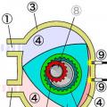
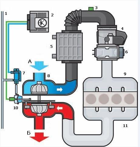
Unit injectors consist of three subsystems: low pressure fuel supply, high pressure fuel supply, air supply and exhaust gas release
The low pressure fuel supply subsystem is required to supply fuel to the high pressure pump and purify the fuel.
The high pressure fuel supply subsystem is used to create high pressure for fuel injection into the combustion chamber.
The subsystem of air supply and exhaust gas release includes devices for cleaning the air entering the engine cylinders and cleaning the exhaust gases after they are released from the cylinders.
The main components of the power supply system of a diesel engine with unit injectors are shown in the figure:
Figure: The power supply system of the diesel engine with unit injectors:
1 - fuel tank; 2 - fuel line to additional heater; 3 - fuel cooler; 4 - fuel temperature sensor; 5 - restrictive valve in the drain pipeline; 6 - drain pipeline; 7 - fuel distributor; 8 - high pressure pipeline; 9 - pump injector; 10 - fuel pump; eleven - pressure reducing valve in the fuel supply line; 12 - check valve; 13 - fuel filter; 14 - low pressure pipeline; 15 - the fuel pump
An electric fuel priming pump 15 located in the tank supplies fuel to the filter. The check valve 12 prevents the fuel from the distributor 7 and the low pressure line 14 from being drained into the tank after the engine stops.
Fuel pump 10 is used to take fuel from the filter and supply it under high pressure to the unit injectors. The pressure reducing valve 11 maintains the pressure of the fuel supplied to the unit injectors within 8.5 kgf / cm2. The restrictive valve 5 maintains the fuel pressure in the drain line at 1 kgf / cm2, thanks to which pressure pulsations in the system are reduced. Due to the high injection pressure in the fuel systems of diesel engines of passenger cars with unit injectors and in some common rail systems, the fuel is heated to such an extent that to prevent damage fuel tank and the fuel level sensor, it must be cooled before being returned to the tank. The fuel returning from the injectors passes through the cooler 3, giving off heat in the cooling circuit. The fuel temperature sensor 4 generates a signal to the engine control unit.
From the filter, fuel is supplied to the supply line in the block head. In the supply line, the fuel flows along the inner walls of the fuel distributor 7 towards the first cylinder. Through holes in the walls, the fuel is fed into the annular cavity between the distributor and the walls of the block head.
Fuel is mixed with heated fuel, which is squeezed out from the unit injectors into the supply line. Due to this, the same temperature is achieved, and therefore the same amount of fuel supplied to all unit injectors, which ensures uniform engine operation. Without a distributor, the fuel would flow unevenly into the unit injectors. The heated fuel squeezed out from the unit injectors into the supply line would be propelled by the incoming fuel from the fourth cylinder towards the first cylinder. This would cause the fuel temperature to rise from the fourth cylinder to the first, and different amounts of fuel would flow to the unit injectors. The result would be uneven engine operation and too high temperatures in the area of \u200b\u200bthe front cylinders.
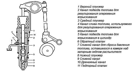
No. 14 Pump-injector with piezoelectric control valve
The pump-nozzle injection system is modern system fuel injection of diesel engines. Unlike the injection system Common rail In this system, the functions of creating high pressure and fuel injection are combined in one device - the unit injector. Actually, the pump nozzle constitutes the injection system of the same name.
The use of pump injectors allows to increase engine power, reduce fuel consumption, emissions harmful substancesas well as the noise level.
The system has its own injector for each cylinder of the engine. The unit injector is driven by the camshaft, which has corresponding cams. The force from the cams is transmitted through the rocker arm directly to the unit injector.
The pump-injector has the following device: plunger; control valve; shut-off piston; check valve; spray needle. http://systemsauto.ru/feeding/shema_nasos_forsunka.html
The plunger is used to create fuel pressure. The translational movement of the plunger is carried out due to the rotation of the camshaft cams, the return movement is due to the plunger spring.
The control valve is designed to control fuel injection. Depending on the actuator, the following valve types are distinguished:
electromagnetic; piezoelectric.
The piezoelectric valve has replaced the solenoid valve. The piezoelectric valve is fast acting. The main structural element of the valve is the valve needle.
The nozzle spring secures the nozzle needle onto the seat.
The spring force is supported by fuel pressure if necessary. This function is realized with a check piston and a check valve. The spray needle is designed to ensure direct injection fuel into the combustion chamber.
The unit injectors are controlled by the engine management system. The engine control unit controls the pump injector valve based on the sensor signals.
The principle of operation of the unit injector
The design of the unit injector ensures optimal and efficient formation of the fuel-air mixture. For this, the following phases are provided during the fuel injection process:
preliminary injection; main injection; additional injection.
Pre-injection is performed to achieve smooth combustion of the mixture during the main injection. The main injection provides high-quality mixture formation at various engine operating modes. An additional injection is carried out to regenerate (remove accumulated soot) of the particulate filter.
The pump injector operates as follows. The camshaft cam moves the plunger down through the rocker arm. Fuel flows through the injector channels. When the valve is closed, the fuel is cut off. The fuel pressure starts to rise. When the pressure reaches 13 MPa, the spray needle, overcoming the force of the spring, rises and the fuel is pre-injected. Fuel pre-injection stops when the valve is opened. The fuel is poured into the supply line. The fuel pressure drops. Depending on the engine operating conditions, one or two preliminary fuel injections can be carried out. The main injection is performed at further movement plunger down. The valve closes again. The fuel pressure starts to rise. When the pressure reaches 30 MPa, the nozzle needle, overcoming the spring force and the fuel pressure, rises and the main fuel injection occurs. The higher the pressure, the more fuel is compressed and accordingly more is injected into the engine's combustion chamber. At a maximum pressure of 220 MPa, the largest amount of fuel is injected, thereby ensuring maximum engine power.
The main fuel injection ends when the valve is opened. This drops the fuel pressure and closes the nozzle needle.
The additional injection is performed with further downward movement of the plunger. The principle of operation of the unit injector with the post-injection is similar to that of the main injection. There are usually two additional fuel injections.
No. 15 Glow plugs
To make it easier to start diesel engines in cold weather (from +5 to –30 ° C), the air in the cylinders is heated using glow plugs. At their core, glow plugs are one of the preheating devices.
The glow plug has different installation locations depending on the design of the diesel engine: in the vortex chamber (engines with a separate combustion chamber); in the prechamber (engines with a separate combustion chamber); in the combustion chamber (engines with an integral combustion chamber).
Structurally, a glow plug is an electric heating device, consisting of a glow plug placed in a protective sheath. There are two types of glow plugs: with a metal spiral; ceramic.
Ceramic glow plugs have a high glow temperature (up to 1350 ° C), a shorter heating time than with a metal coil (2 sec) and, accordingly best performance cold start. The leading manufacturers of glow plugs are companies Bosch, NGK, Lucas... The glow plugs are controlled using relay or separate electronic control unit... These devices regulate the amount of voltage supplied to the plugs and, thereby, provide the required heating torque and temperature, as well as the heating duration.
The glow plugs turn on under certain temperature conditions during engine start ( the first position of the key in the ignition lock), which is signaled by control lamp on the dashboard... After the lamp goes out and the warm-up is over, the engine is started ( second position of the key in the ignition lock). On modern diesel engines, glow plugs, in addition to the preliminary (pre-starting) glow, provide additional glow after starting the engine... Additional heating is produced to reduce the noise during combustion of the mixture on a cold engine, as well as to reduce harmful emissions in atmosphere. The additional heating phase lasts about 3 minutes and ends when the coolant reaches a temperature of 20-30 ° C.
No. 16) Purpose of inflation, existing systems inflating, inflating with a mechanical drive!
Aspiration is an increase in the amount of fresh charge of the combustible mixture supplied to the internal combustion engine by increasing the intake pressure. Supercharging is usually used to increase power (by 20-45%) without increasing the mass and dimensions of the engine, as well as to compensate for the power drop in high altitude conditions. Supercharging with "quality control" can be used to reduce the toxicity and smoke of the exhaust gases. Aggregate supercharging is carried out using a compressor, turbocharger or in combination. The most widespread is supercharging with the help of a turbocharger, for which the energy of the exhaust gases is used to drive.
Aggregate supercharging is used in almost all types of transport diesel engines (ship, diesel, tractor). Pressurization on carburetor engines limited by the occurrence of detonation. The main disadvantages of aggregate supercharging include:
an increase in the mechanical and thermal stress of the engine due to an increase in gas pressure and temperature;
decrease in efficiency;
complication of the design.
Aggregate-free supercharging includes:
dynamic (previously called inertial, resonant, acoustic), in which the effect is achieved due to oscillatory phenomena in pipelines;
high-speed, used on piston aircraft engines at heights higher than the design one and at speeds over 500 km / h;
refrigeration, achieved by evaporation of fuel or any other flammable liquid with a low boiling point and high heat of vaporization in the incoming air.
Dynamic supercharging is becoming more and more common on transport internal combustion engines, which, with insignificant changes in the design of the pipelines, leads to an increase in the filling factor up to a wide range of changes in the engine speed. The boost during boost makes it possible to boost the diesel engine in terms of energy indicators in the case of a simultaneous increase in the cycle fuel supply, or to improve economic indicators while maintaining power (with the same cycle fuel supply). Dynamic pressurization increases the durability of cylinder-piston group parts due to lower thermal conditions when working on lean mixtures.
There are several pressurization systems. First of all, they should include the most common type - turbocharging - charging through the use of the energy of the exhaust gases (Fig. A). This type of supercharging will be discussed in more detail below.
The second supercharging option is supercharging from a supercharger - the so-called SUPERCHARGER. On modern engines this scheme is rarely used due to the complexity of the supercharger design and its lack of reliability. Its advantage over turbocharging is a higher boost pressure in low modes, as well as the absence of the so-called "turbo lag", i.e. characteristic "dip" of power with a sharp opening of the throttle valve. This determines the field of application of the drive supercharger - mainly on not too high-speed engines (FORD, GM), although in recent years there has been a tendency to use them on high-speed engines (MERCEDES).
A COMPREX wave pressure exchanger is installed on diesel engines of MAZDA vehicles, which provides pressurization due to the interaction of pressure and vacuum waves propagating in the channels of the rotating rotor. This type of supercharging allows you to achieve higher boost than other supercharging systems, but has not yet gained popularity due to the complexity of the design.
No. 17) turbocharger, its displacement and operating principle
Turbocharger base
At the heart of an engine's turbocharging system, and at the same time its most complex element, is the turbocharger. The principle of operation of a turbocharger is that the energy remaining in the exhaust gases does not go into the atmosphere, but goes to increase the pressure and density of the air entering the engine.
The gases exhausted by the engine through the exhaust manifold enter the turbine housing (hot snail). The gas pressure and the thermal energy of the gases rotate the turbine wheel (hot impeller), which in turn rotates the compressor wheel (cold impeller). The exhaust gases are then released into the atmosphere.
When the compressor wheel rotates, it draws in air through the air filter. The compressor wheel blades accelerate and push the air into the compressor casing (cold snail) where the air is compressed and intake manifold engine. The air leaving the compressor not only has high blood pressure, but also a temperature that reduces the charge density, which adversely affects the filling and, therefore, the engine power. Therefore, on many turbocharged engines, in order to increase the air density and, accordingly, improve the filling of the cylinders, intercooler is used. For this, after the compressor, the air is directed into a special "air-to-air" radiator, installed next to the radiator of the cooling system.
No. 18) electronic turbocharger control circuit
vacuum line
the engine control unit
boost pressure and intake air temperature sensors
choke control unit
intercooler
exhaust gas recirculation valve
boost pressure limiting valve
turbocharger
intake manifold
vacuum drive of guide vanes
an exhaust manifold
A - air
B - exhaust gases
No. 19. TURBOCHARGER WITH VARIABLE TURBINE GEOMETRY (VGT).
VGT (Variable Geometry Turbine) is a specific type of turbocharger that uses the energy of the exhaust gas stream. The graph below shows comparative characteristics the speed capabilities of vehicles equipped with a conventional turbocharger and a VGT turbocharger. Maximum speed: VGT allows you to increase maximum speed by 4.1%.
Acceleration time: Compared to a conventional VGT, the acceleration time from 0 km / h to 100 km / h is reduced by 15.1%.
Acceleration time during acceleration: this characteristic shows the car's capabilities during hard acceleration (from 60 km / h to 100 km / h) while driving. The smaller it is, the better the performance.
OPERATING PRINCIPLE
Functioning when low revs engine
When the engine is running at low speeds, the amount of exhaust gases is relatively small, the energy of their flow is small and in a conventional turbocharger there is no significant turbocharging effect, and in the VGT turbocharger there is the possibility of passing exhaust gases through a narrower section of the bore, due to which the speed and energy of their flow increase significantly. Consequently, the VGT system improves the engine's low rpms performance.
Principle of operation at low engine speeds
This design uses the principle of the Venturi tube, the essence of which is that when air flows through a narrowed section (point "A"), the flow rate increases and the pressure decreases. As the bore diameter decreases, the flow rate will increase proportionally (see equation).
Functioning at high engine speeds
At high engine speeds, the energy of the exhaust gas stream is high enough to create the required force to rotate the turbine. In this case, the cross-section of the passage channel increases and the entire flow of exhaust gases rushes to the turbine, while the pumping resistance of the exhaust tract decreases. The engine output will depend on the intake air volume.
VGT system control
The control signal of the VGT system is generated based on the analysis of the signals from the speed sensors crankshaft (CV), accelerator pedal position, atmospheric pressure, boost pressure, coolant (coolant) temperature, intake air temperature and clutch engage signal.
In this case, the ECU determines the driving conditions of the vehicle and the required boost pressure depending on the engine speed and the amount of fuel injected. Then the ECU outputs to solenoid valve corresponding signal with a frequency of 3 00 Hz with specified parameters. This system allows you to maintain efficient engine operation at any speed.
It should be noted that the boost pressure sensor is also designed to measure the actual air pressure in the intake manifold and provide feedback to the boost pressure control system (via the ECU). This feedback contributes to precise control.
Conditions precluding the possibility of the VGT system functioning
1. Engine speed below 700 rpm
2. Coolant temperature dropped to 0 °
3. Damage to any part of the EGR system
4. Damage to the stem of the actuator system VTG
5. Faulty boost pressure sensor
6. Damage to the air flow sensor (MAF)
7. Damage to the throttle valve
8. Malfunction of the accelerator pedal position sensor
If at least one of these conditions is present, the ECU stops controlling the VTG system.
No. 20. Additional measures to reduce the toxicity of exhaust gases
In order to reduce the level of emissions into the atmosphere of toxic constituents that enter the composition of engine exhaust gases as a result of evaporation and incomplete combustion of fuel, as well as to maintain the efficiency of engine output and reduce fuel consumption, modern cars equipped with a number of special systems, which can be grouped under the general name of engine management and emission control systems. Let's consider the most common systems:
1. Fuel dosage control.
The control over the composition of the mixture is carried out by the fuel control systems.
With an excess air ratio λ \u003d 0.9, the engine operates at maximum power and torque.
Optimum efficiency and minimum CO and CH emissions are achieved when working with mixtures with a coefficient of λ \u003d 1.1. However, the content of nitrogen oxides in the exhaust gases is at its maximum.
To operate the engine in the mode idle move the composition of the mixture should be characterized by the coefficient λ \u003d 0.9 - 1.05.
The forced idle (engine braking) mode allows you to completely turn off the fuel supply to the cylinders. There will be no toxic emissions.
2. Recirculation of exhaust gases.
Directing some of the exhaust gases back into the combustion chamber (recirculation) is used to reduce the combustion temperature of the mixture in order to reduce the formation of nitrogen oxides and fuel consumption. However, this also reduces engine power.
Exhaust Gas Recirculation ( eGR system) is implemented in two ways: 1) internal recirculation, provided by the control of the valve timing, and primarily by valve overlap; 2) external recirculation, in which the exhaust gases are taken at the outlet of the exhaust manifold and through the valve system are sent back to the combustion chamber.
3. Ventilation of the engine crankcase.
Since the toxicity of crankcase gases is many times higher than that of exhaust gases, their release into the atmosphere is prohibited. When the engine is running, crankcase gases, by the crankcase ventilation system, are bypassed into the engine intake tract, where they are mixed with working gases and, at the intake stroke, enter the cylinder for subsequent afterburning.
4. Thermal afterburning of exhaust gases.
Afterburning of the exhaust gas components that have not burned out in the engine cylinder occurs in the exhaust system, where additional air is supplied by a special supercharger, which is necessary for the afterburning reaction to proceed.
With the development of catalytic exhaust gas cleaning systems, thermal afterburning is no longer used as widely as before.
5. Catalytic afterburning.
Afterburning of the exhaust gas components takes place in a special device - a catalytic converter. The catalytic converter is mounted in the exhaust system and is located under the underbody of the vehicle. The catalytic converter housing has a ceramic block, which is coated with a catalytic material (metals - Pt, Rh, Rd).
Oxidative neutralizers oxidize CO and CH using residual oxygen in lean mixtures or supplying additional air to the system.
Reducing type neutralizers reduce NOx to harmless nitrogen.
Two-component neutralizers combine oxidation and reduction types of neutralizers.
Three-way catalysts (selective catalytic converters) with λ-probe are by far the most widespread and effective exhaust gas treatment system. The oxygen sensor (λ - probe) of this system is used to calculate the ratio of air to fuel in the combustible mixture.
6. Systems with feedback (λ - regulation).
This system neutralizes up to 96% of harmful substances in exhaust gases. The system uses two oxygen sensors. One sensor is installed in front of the catalytic converter, the other after it. The sensors, by measuring the amount of free oxygen in the exhaust gases, through the fuel management system influence the composition air-fuel mixtureentering the engine cylinders. To ensure proper cleaning of exhaust gases by a neutralizer, the engine must operate in a narrow range of values \u200b\u200bλ \u003d 1 ± 0.005, called a "window" catalytic converter.
No. 21. Scheme of a system of continuous variable valve timing with a hydraulically controlled clutch. Adjustable valve timing.
The variable valve timing system (commonly accepted international name Variable Valve Timing, VVT) is designed to regulate the parameters of the gas distribution mechanism depending on the engine operating modes. The use of this system provides increased engine power and torque, fuel efficiency and reduced emissions.
The adjustable parameters of the gas distribution mechanism include:
The moment of opening (closing) the valves;
Duration of valve opening;
Valve lift.
Together, these parameters make up the valve timing - the duration of the intake and exhaust strokes, expressed by the angle of rotation of the crankshaft relative to the "dead" points. The valve timing is determined by the shape of the camshaft cam acting on the valve.
Different engine operating modes require different valve timing. So, at low engine speeds, the valve timing should have a minimum duration ("narrow" phases). On the other hand, at high revs, the valve timing should be as wide as possible and at the same time ensure the overlap of the intake and exhaust strokes (natural exhaust gas recirculation).
The camshaft cam has a certain shape and cannot simultaneously provide narrow and wide valve timing. In practice, the cam shape is a compromise between high torque at low rpm and high power at high rpm. This contradiction is just resolved by the variable valve timing system.
Depending on the adjustable parameters of the gas distribution mechanism, the following methods of variable valve timing are distinguished:
turning the camshaft;
use of cams with different profiles;
change in valve lift.
The most common are variable valve timing systems that use a camshaft rotation:
VANOS (Double VANOS) from BMW;
VVT-i (Dual VVT-i), Variable Valve Timing with intelligence from Toyota;
VVT, Variable Valve Timing from Volkswagen;
VTC, Variable Timing Control from Honda;
CVVT, Continuous Variable Valve Timing from Hyundai, Kia, Volvo, General Motors;
VCP, Variable Cam Phases from Renault.
The principle of operation of these systems is based on turning the camshaft in the direction of rotation, which achieves an early opening of the valves in comparison with the initial position.
The variable valve timing system of this type has the following general arrangement:
Hydraulic clutch;
Control system.
The hydraulically operated clutch (the common name for the phase shifter) directly rotates the camshaft. The clutch consists of a rotor connected to a camshaft and a housing, which is a camshaft drive pulley. There are cavities between the rotor and the housing, to which engine oil is supplied through the channels. Filling a cavity with oil ensures that the rotor rotates relative to the housing and, accordingly, rotates the camshaft at a certain angle.
Most of the hydraulic clutch is installed on the intake camshaft. To expand the control parameters in individual designs, the clutches are installed on the intake and exhaust camshafts.
The control system provides automatic regulation of the hydraulic clutch operation. Structurally, it includes input sensors, the electronic unit control and executive devices. Hall sensors are used in the control system to evaluate positions camshafts, as well as other sensors of the engine management system: crankshaft speed, coolant temperature, air mass meter. The engine control unit receives signals from sensors and generates control actions on an actuator - an electro-hydraulic valve. The distributor is a solenoid valve and provides oil supply to and from the hydraulic clutch, depending on the engine operating conditions.
The variable valve timing system provides for operation, as a rule, in the following modes:
Idling (minimum crankshaft speed);
Maximum torque.
No. 22. System for changing the valve lift
The representative of the mechanical drive is the Valvetronic system, which is used on bMW cars, which controls the lift of the intake valves and dispenses the working mixture entering the cylinders, which makes it possible to increase the efficiency of the engine without losing power while meeting the Euro-4 standards and maintaining the injection system into the intake manifold. By changing the valve stroke to high frequency rotation of the crankshaft provides the best ventilation of the cylinder and filling with a fuel-air mixture. At minimum crankshaft speed, valve travel is minimal. This reduces the valve overlap effect, which minimizes fuel consumption. With an increase in the crankshaft speed, the valve opening increases. At the same time, the resistance to gas flows inside the cylinder decreases, the rate of purging and filling the cylinder with the fuel-air mixture increases. In addition, the action of the inertial effect is increased. The air-fuel mixture inside the cylinder is locked by valves at a much higher pressure, its density is higher than at the minimum crankshaft speed. Due to the variable valve travel, friction losses are reduced relative to a conventional valve drive due to the low resistance at low valve travel.
Diagram of the control system for lifting the intake valves of the Valvetronic BMW engine:
1 - lever spring; 2 - electric motor; 3 - worm gear wheel; 4 - eccentric control shaft; 5 - a camshaft; 6 - lever with roller support; 7 - rocker; 8 - valve.
An additional lever 6 is located between the camshaft 5 and each pair of intake valves 8, which is attached to the axle. The electric motor 2, through a worm gear, turns the eccentric control shaft 4 by an angle determined electronic system management. The valves are opened directly by levers 6 with roller bearings when acting on the rocker arms, which are supported on one side by the valve, and on the other by the hydraulic pusher. Levers 6 by means of coil springs 1 are pressed against the camshaft cam. To reduce frictional losses, needle roller bearings are installed on the axles of the lever with a roller support and the rocker arm. When turning the eccentric shaft, the eccentric running onto the lever 6 turns it at a certain angle. By moving the eccentric shaft, the electric motor increases or decreases the intermediate lever arm, thereby lengthening or shortening the intake valve travel in accordance with the engine load. Considering that the eccentric displaces the pusher axis, it has electric drive, this allows you to set the angle of rotation non-linear and program it individually for each motor.
The change in the valve lift can be carried out by changing the height of the camshaft cam acting through the rocker arm on the valve. This solution, called "VTEC-System", is used by Honda. The abbreviation VTEC stands for Variable Valve Timing and Lift Electronic Control. The switching mechanism is installed on the axis of the rocker arms. This system allows you to change the valve stroke depending on the speed of the crankshaft (high or low), as well as turn off the cylinders from work. Camshaft, in addition to two cams of small height 3, has a large cam 6 in the middle of them to drive the valves of each cylinder with increased stroke and opening duration. A high-height cam acts on an additional rocker arm 7, which is supported by a special spring device 9. Inside the camshaft axis there is a channel 2 for supplying oil to a locking plunger, which consists of two parts. The oil is supplied to the system parts through a channel made inside the camshaft. To create the required pressure, an additional oil pumppowered by the main oil line. The locking plunger consists of two pistons that can move under oil pressure and connect the additional rocker arm 7 with the main rocker arms 4. In this case, the cam 6, which has a greater height than the cams 3, acting on the additional rocker arm 7 connected to the main rocker arms 4, opening the valves by a large amount and increasing the duration of the supply of the air-fuel mixture. When the oil supply is interrupted, the closing plunger under the influence of the spring returns to its original state, and the additional rocker arm is disconnected from the main ones.
No. 23. Electromechanical valve drive
Improvement in cylinder filling can be achieved without increasing the number of valves, lengthening the intake phase and increasing valve lift by using the Electromagnetic Valve Actuator (EVA). Such systems are currently being intensively developed both in Europe and the USA.
The solenoid valve actuator is a spring-loaded valve that is placed between two electromagnets that hold it in its extreme positions: closed or fully open. A special sensor provides the control unit with information about the current valve position. This is necessary in order to reduce its speed to the minimum at the time of landing in the saddle.
The principle of the system is shown in the figure. As can be seen from the operation diagram of this system, the valve control system completely lacks a camshaft with its own drive, which is replaced by electromagnets for each valve.
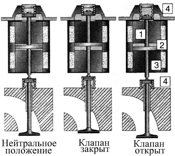
Figure: Electromechanical valve drive:
1 - valve opening solenoid; 2 - anchor; 3 - valve closing solenoid; 4 - valve spring
The solenoid armature forms a combination with two springs to open and close the valve. When no electric current is supplied to the electromagnets, the valve and electromagnet springs hold the valve in the middle position, corresponding to half the valve travel, while it is half-open, which makes it easy to turn the engine crankshaft at the initial stage of start-up. When the required speed is reached, a signal is sent from the control unit and a signal is supplied to the upper opening electromagnet electricity, the valve closes. At the same time, fuel is injected.
№24. Hydraulic drive valves
Application electromagnetic drive valves require a lot of electricity to open them, so German engine manufacturers suggest opening valves using hydraulics and controlling hydraulics using electricity. Unlike other types of valve opening, the use of an electro-hydraulic valve drive eliminates not only the camshaft and throttle valve, but also valve springs. When using this type of valves, along with simple opening and closing valves and valve travel, it is possible to change the valve timing and their operation independently for each cylinder, thereby reducing fuel consumption and emissions of toxic substances in the exhaust gases and increasing engine power.
Diagram of the electro-hydraulic valve drive:
1 - high pressure pump; 2 - high pressure line (50 ... 200 kgf / cm2); 3 - high pressure control valve; 4 - control pressure line (5 ... 20 kgf / cm2); 5 - block of electro-hydraulic valve lift; 6 - valve lift regulator; 7 - solenoid valve on the low pressure line; 8 - low pressure line (less than 5 kgf / cm2); 9 - valve of the gas distribution mechanism; 10 - high pressure line solenoid valve; 11 - cylinder; 12 - piston.
The principle of the system is as follows. The high pressure pump creates oil pressure in the system up to 200 kgf / cm2. Solenoid pressure reducing valve 3 regulates the pressure in the high pressure line within 50 ... 200 kgf / cm2 according to the signal from the control unit, depending on the crankshaft speed, load, temperature, etc. This valve regulates the variable stroke of the valve lift simultaneously for all valves immediately. If voltage is applied to the solenoid valve 10, it opens and oil from the high pressure line enters the cylinder from above the piston. The solenoid valve on the low pressure line 7 is closed at this time, since it is not energized. The piston, acting on the valve of the gas distribution mechanism, moves it down, thus the valve opens. Depending on the engine operating mode, the valve lift regulator 6 is activated, changing the landing speed of all valves at the same time. The change in valve timing occurs when the time when voltage is applied to the solenoid valve on the high pressure line 10 changes.
When the solenoid valve 10 is de-energized and the oil from the high pressure line enters the cylinder from the bottom of the piston. The piston, acting on the valve of the gas distribution mechanism, moves it upward, thus the valve closes. Oil from the space above the piston is fed into the low pressure line and then fed back to the pump.
In order to increase the opening force of the valve and at the same time reduce energy consumption with a large valve opening stroke, two-piece pistons are used. With an average pressure of about 100 kgf / cm2 and a relatively short response time, the full valve stroke is 1 mm, and the landing speed ranges from 0.05 to 0.5 m / s.
The electro-hydraulic valve drive is connected to the engine oil circulation system. Common to the engine lubrication system are the oil sump, the oil pump for supplying oil to the engine lubrication system and to the valve drive high pressure pump, the oil filter and the oil drain line from the block head. To the oil used, the same for common system lubrication and valve drives are subject to high quality requirements for long-term operation and viscosity characteristics. Therefore, the lubrication system must be filled with 0W40 oil. To monitor the viscosity during engine operation, a special sensor is provided that sends a signal about the loss of viscosity.
Electro-hydraulic valve lift units can be installed and mounted independently of each other. The flat surface of the block, made with high precision, allows providing the necessary hydraulic tightness of the connection between the block and the engine housing.
No. 25. Systems for changing the compression ratio of the fuel-air mixture. Various ways shutdown of cylinders.
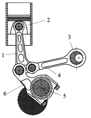
The compression ratio of an internal combustion engine is closely related to efficiency. In gasoline engines, the compression ratio is limited to the knock combustion region. These limitations are of particular importance for engine operation at full load, while at partial loads, the high compression ratio does not pose a knock hazard. To increase engine power and improve efficiency, it is desirable to lower the compression ratio, however, if the compression ratio is low for all ranges of engine operation, this will lead to a decrease in power and an increase in fuel consumption at partial loads. In this case, the values \u200b\u200bof the compression ratio, as a rule, are chosen much lower than those values \u200b\u200bat which the most economical indicators of engine operation are achieved. Deliberately impairing the efficiency of engines, this is especially pronounced when operating at partial loads. Meanwhile, a decrease in the filling of cylinders with a combustible mixture, an increase in the relative amount of residual gases, a decrease in the temperature of parts, etc. create opportunities to increase the compression ratio at partial loads in order to improve the engine's economy and increase its power. Variable compression engine options are being developed to address this tradeoff, one of the most common variable compression engine options shown in the illustration.
At partial loads, the additional connecting rod 4 takes the lowest position and raises the area of \u200b\u200bthe piston's working stroke. The compression ratio is maximum. At high loads, the eccentric on the shaft 3 raises the axle of the upper head of the additional connecting rod 4. This increases the over-piston clearance and decreases the compression ratio.
The cylinders of the engine and the head of the block are made as a monoblock, that is, a single block, and not separately, like in conventional engines. A separate block is also a crankcase and a connecting rod-piston group. The monoblock can be moved in the crankcase. In this case, the left side of the monoblock rests on the axle 1 located in the block, which serves as a hinge, the right side can be raised or lowered using a connecting rod 3 controlled by an eccentric shaft 4.
For sealing the monoblock and the crankcase, a corrugated rubber cover 2. The compression ratio changes when the monoblock is tilted relative to the crankcase by means of a hydraulic drive with a constant piston stroke. The deviation of the monoblock from the vertical leads to an increase in the volume of the combustion chamber, which causes a decrease in the compression ratio.
As the pitch angle decreases, the compression ratio increases. The maximum deviation of the monoblock from the vertical axis is 4%.
At the minimum crankshaft rotation speed and fuel supply reset, as well as at low loads, the monoblock takes the lowest position in which the combustion chamber volume is minimal (compression ratio - 14). The boost system is turned off and air enters the engine directly.
Under load, due to the rotation of the eccentric shaft, the connecting rod deflects the monoblock to the side, and the volume of the combustion chamber increases (compression ratio - 8). In this case, the clutch engages the supercharger, and air begins to flow into the engine under excess pressure. The optimal compression ratio is calculated by the electronic system control unit, taking into account the crankshaft rotation speed, load, fuel type and other parameters.
Due to the need to quickly respond to changes in the compression ratio in this engine it was necessary to abandon the turbocharger in favor of mechanical supercharging with intermediate air cooling with a maximum boost pressure of 2.8 kgf / cm2.
The fuel consumption for the developed engine is 30% less than that of conventional engine of the same volume, and the indicators for the toxicity of the exhaust gases correspond to the current standards.
The main ways to turn off the cylinders: turn off the cylinders by turning off the fuel supply while maintaining a variable degree of throttling of idle cylinders (method 1); turning off the cylinders by turning off the fuel supply with the simultaneous communication of the idle cylinders directly with the atmosphere or with the exhaust pipeline (method 2); shutting off the cylinders by holding the intake and exhaust valves in the closed position and stopping gas exchange in idle cylinders (method 3).
No. 26. Recirculation of exhaust gases in a diesel engine.
The exhaust gases of diesel engines contain a small amount of harmful substances, so previously it was not necessary to install on the car special devices... But over time, the rules have tightened. And all thanks to the content of soot particles and nitrogen oxide in the exhaust. Therefore, for diesel engines, systems began to be used to reduce the toxicity of exhaust, which include the recirculation of exhaust gases of diesel engines together with a neutralizer, which makes it possible to reduce the toxicity of exhaust gases by reducing nitrogen oxide, and using the resulting oxygen for afterburning carbon monoxide along with unburned hydrocarbons, and soot filter.
The particulate filter is a porous filter material made of silicon carbide. If we consider the designs of past years, then they periodically cleaned the filters from accumulated soot with exhaust gases, whose temperature was increased, making the mixture enriched. The filter was cleaned by the command of the control unit after 400 500 km of run. In this case, there was a sharp increase in emissions of other harmful substances. Therefore, modern particulate filters work in conjunction with an oxidizing neutralizer, with the help of which the soot is burned at the lowest temperature of about 250 degrees Celsius.
In the new generation filters, the principle has not changed much: arrest and destruction. How to achieve the required temperature for the combustion of soot particles? On the one hand, the filter is placed behind the exhaust manifold. On the other hand, every 300-500 km of run, the controller turns on the "multiphase injection" mode, as a result of which the amount of fuel entering the cylinder increases. Most importantly, the surface of the filter element is covered with a thin layer of catalyst, which makes it possible to further increase the temperature of the exhaust gases to the required one (560 600 deg. Celsius).
The filter element is a ceramic microporous sponge. The wall thickness between its channels is no more than 0.4 mm, therefore the filtering surface is large. Such a "sponge" is often made from ultrafine steel fibers coated with a catalyst. Due to dense packing, up to 80% of particles ranging in size from 20 to 100 nm are retained.
New filters were used to control engine operation. Pressure sensors are installed at the inlet and outlet of the filter, and after the signal is received from them, the enrichment mode is activated. When the difference between the readings becomes significant, the computer will indicate that the "sponge" is clogged with soot. Burnout control is carried out using a temperature sensor.
An example is the modern mechanism for recirculation of exhaust gases of diesel engines, an electronic system that controls diesel engine EDS. The design is represented by a multicomponent exhaust system, which includes 7 sensors: 2 lambda probes, 2 temperature, 2 pressure, one level of soot in the exhaust. This also includes 3 cleaning elements, a catalytic converter, a storage catalyst, and a storage-type particulate filter. With the help of sensors installed in the exhaust system, the processes of mixture formation and combustion have been optimized. Many engine systems, fuel and air supply, exhaust gas recirculation, electronic throttle and turbocharging have been transferred to control the particulate filter. Pressure sensors installed at the inlet and outlet control the degree of contamination from the particulate filter. The quality of the catalysts is assessed by the data of the lambda probes installed at the inlet and outlet. The operation of the engine system is corrected based on the readings of lambda probes, temperature sensors and the level of soot at the outlet. With the help of a catalytic converter, toxic substances are "processed" into non-toxic and low-toxic compounds (water, nitrogen, carbon dioxide), and with the help of a catalyst - a storage device, additional purification of nitrogen oxide and soot particles takes place.
No. 27. Additional air supply system.
This system draws air for 65 seconds behind the exhaust valves when the engine coolant temperature is between 15 ° and 35 ° C. As a result, oxygen-enriched exhaust gases are emitted from the engine, which contribute to afterburning and allow the catalyst to warm up faster. The auxiliary air system is controlled by the Motronic ECU via the secondary pump relay to the secondary air inlet valve and the combination valve. After each subsequent engine start and until the engine temperature reaches 85 ° C, the additional air supply system is activated with a delay of 20 s and runs at idle speed for 5 s, while the system is monitored by a self-diagnosis device. The condition of the parts of the additional air supply system is monitored either in the "final report on malfunctions", or if any defect appears, it will be recorded in the malfunction recorder. When accessing the memory of the fault recorder (work is carried out at the service station), the fault is easily diagnosed, and then can be corrected. For some positions (see Fig. 99) the following additional explanations are given: - additional air is pumped into the air duct 1 of the cylinder head;
The lifting lug 4 is bolted to the left of the cylinder head;
An additional air supply valve is screwed into the clamp 5;
Plug-in block 7 is put on the inlet valve (black);
The vacuum hose 8 is connected between the upper part of the intake manifold and the fuel rail;
Inlet hose 9 goes from the top air filter... Its connection must be sealed, without air intake;
The plug-in block 11 refers to the air pump motor. It is black and has two pins;
The holder 12 holds the air pump motor. It is screwed into the cooling fan air intake;
A hose clip 14 secures the inlet hose;
The pressure hose 15 is attached between the pump motor 10 and the combination valve 17;
The holder 16 secures the combination valve to the dipstick guide tube for checking the oil level;
Always replace O-ring 19.
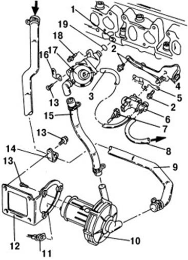
Figure: 99. Elements of the additional air supply system: 1 - air channel in the cylinder head; 2 - bolt, 25 Nm; 3 - vacuum hose; 4 - lifting lug; 5 - holder; 6 - additional inlet valve * / **; 7 - plug block; 8 - vacuum hose; 9 - inlet hose; 10 - air pump motor *; 11 - plug block; 12 - holder; 13 - bolt, 10 Nm; 14 - hose clip; 15 - hose under pressure; 16 - holder; 17 - combined valve; 18 - bolt, 15 Nm; 19 - O-shaped sealing ring
No. 28. Fuel tank ventilation system
The main input signals to the engine control unit for regulating the fuel tank ventilation system are:
crankshaft speed
mass air flow meter signal corresponding to engine load
engine temperature
oxygen sensor signals
signals from control units throttle valves
Fuel vapors are retained in adsorber 3. It is a container with connected pipes, filled with a surfactant - an adsorbent. Adsorbents, in addition to their high absorption capacity, should be distinguished by stable characteristics when the ambient temperature changes, effective desorption (release of accumulated vapors) and stability with multiple repetition of adsorption-desorption cycles, insensitivity to atmospheric moisture, high mechanical strength in order to avoid abrasion during vehicle operation ... The most acceptable adsorbent is activated carbon AG-3, obtained from coal and semi-coke. After processing the input signals, the engine control unit issues a command to open the solenoid valve 4. As a result, the fuel vapors accumulated in the adsorber are discharged into the intake manifold 6 of the engine and then burned in its cylinders. In this case, the ratio of fuel and air in the mixture changes for a short time. This change in the mixture is recorded by oxygen sensors 10, according to the signals of which the control system makes the necessary correction. Crankcase ventilation. The crankcase ventilation system is designed to reduce the emission of harmful substances from the engine crankcase into the atmosphere. When the engine is running, exhaust gases can leak from the combustion chambers into the crankcase. The crankcase also contains oil, gasoline and water vapors. Together they are called blow-by gases. The accumulation of blow-by gases impairs the properties and composition engine oil, destroys metal parts of the engine.
On modern engines, a closed-type forced crankcase ventilation system is used. Crankcase ventilation system different manufacturers and on different engines may have a different design. At the same time, the following general structural elements this system:
oil separator;
crankcase ventilation valve;
air connections.
With the help of ventilation, both gasoline vapors and exhaust gases are removed from the engine crankcase. There are two types of crankcase ventilation: closed and open. Each has its own disadvantages and advantages.
Open ventilation
does not work at XX or at low speed;
saturates the engine compartment with exhaust gases and pollutes environment (which is relevant, since you are also in it in the immediate vicinity of the source of pollution);
there is a possibility of sucking in the surrounding unfiltered air when the motor cools down;
structurally simpler (only one branch pipe on the cover of the pushers).
Closed ventilation
increases the gumming of the carburetor (however, this was important in the 1960s, taking into account the oils available then; this is less critical when using modern high-quality semi-synthetic engine oil);
possible condensation problems;
at high speeds, too much thrust is created in the suction, and it is believed that oil, which tends to oxidize from air oxygen, shortens its service life;
possible flashes of the fuel-air mixture in the carburetor;
more efficient in terms of oil consumption;
No. 29. Cooling system with electronic control
The parameters of engine operation, among other things, are significantly affected by the optimal temperature regime coolant. The increased coolant temperature at partial load provides favorable conditions for the engine, which has a positive effect on fuel consumption and emissions. Due to the lower coolant temperature at full load, the engine power is increased by cooling the intake air and thereby increasing the amount of air entering the engine. The use of an electronically controlled cooling system allows the fluid temperature to be controlled at partial engine load between 95 and 110 ° C and at full load between 85 and 95 ° C. The electronically controlled engine cooling system optimizes the coolant temperature according to the engine load. According to the optimization program stored in the memory of the engine control unit, the required operating temperature of the engine is achieved through the action of the thermostat and the fans. Thus, the coolant temperature is matched to the engine load. The main distinguishing components of an electronically controlled cooling system from a conventional one is the presence of a coolant distributor with an electronic thermostat. In connection with the introduction of electronic regulation of the cooling system, the following additional Information:
thermostat power supply (output signal)
radiator outlet coolant temperature (input signal)
radiator fan control (2 outputs)
position of the potentiometer at the heating controller (input signal)
When the coolant heats up, the filler 2 liquefies and expands, which leads to the lifting of the pin 1. When no current is supplied to the heating resistance, the thermostat acts as a traditional thermostat, but its response temperature is increased to 110 ° C (coolant temperature at the engine outlet). A heating resistor 3 is built into the filler. When a current is applied to it, it heats the filler 2, which expands at the same time, as a result of which the pin is extended by a certain amount "x" depending on the degree of heating of the filler. The pin 1 now moves not only under the action of the heated coolant, but also under the action of heating the resistance, and the degree of its heating is determined by the engine control unit in accordance with the program for optimizing the coolant temperature set in it. Depending on the nature of the pulse and the time of its delivery, the degree of heating of the filler changes.
The distributor is located instead of the connecting nipples at the cylinder head and is a device for directing the coolant flow into a small or large circle. At full engine load, intensive cooling of the coolant is required. The thermostat in the distributor is energized and a path is opened for fluid from the radiator. At the same time, by means of a mechanical connection, the small valve disc closes the path to the pump in the small circle. The pump supplies the coolant from the cylinder head directly to the radiator. The cooled liquid from the radiator enters the lower part of the engine block and from there is sucked in by the pump. Combined coolant circulation is also possible. One part of the liquid runs in a small circle, the other in a large circle.
Thermostat control in an optimized engine cooling system (coolant movement at low or a large circle) is carried out in accordance with three-dimensional dependence graphs optimal temperature coolant from a number of factors, the main of which are engine load, engine speed, vehicle speed and intake air temperature. These graphs determine the value of the nominal coolant temperature.
No. 30. Engines running on gaseous fuels. The carburation-based power system mounted on gasoline engine with electronic injection system.
AND) Gas engine - an internal combustion engine that uses liquefied petroleum gases (propane-butane) or natural gas (methane) as fuel.
The difference from gasoline engines operating in this cycle is a higher compression ratio (about 17). This is explained by the fact that the gases used have a higher octane numberthan gasoline.
Engines are divided into:
special (or modified), intended only for operation on gas, gasoline is used for a short-term in case of malfunction of gas equipment, when it is not possible to make repairs on site;
universal, designed for long work both gas and gasoline.
On a car, the liquefied propane-butane mixture is in steel seamless (no welded seams) cylinders installed on the frame, under the floor of the bus or in the trunk of a passenger car. Liquefied gas is in a cylinder under a pressure of 16 atmospheres (the cylinder is designed for a maximum pressure of 25 atmospheres).
Compressed cylinders natural gas located on the frame, under the floor of the passenger compartment or on the roof (compressed gas is not used on passenger cars - there is very little space for bulky and heavy cylinders). Compressed methane is under pressure up to 150 atmospheres. Several cylinders are combined into a common line, there is a common filling valve, each cylinder also has its own valve.
Gas from the common line enters the evaporator (heater) - heat exchanger included in the system liquid cooling, after the engine warms up, the gas is heated (liquefied gas evaporates) to a temperature of ≈75 ° C. Then the gas passes through the main filter.
Then the gas enters a two-stage gas reducer, where its pressure is reduced to working pressure.
Further, the gas enters the mixer (either into the mixer carburetor or into the mixing spacer under the standard carburetor, it is determined by the design of the fuel equipment). The mixers are arranged similarly to carburetors, they have a throttle and an air valve, an idle system, a system for working on full power and etc.
B) The LPG fuel supply system, based on the carburation principle, is used both on gasoline engines equipped with a carburetor and on engines equipped with a gasoline injection system. A fuel system that operates on the carburation principle when used on engines with electronic injection gasoline, in addition to the main elements of a conventional injection system, contains a receiver 2, a reducer-evaporator 6, a servomotor for controlling gas consumption 7, a pipeline for supplying gas to the diffuser.
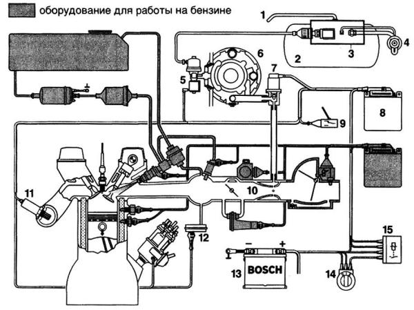
Figure: LPG fuel supply system based on the carburation principle installed on a petrol engine with electronic injection system:
1 - ventilation pipe for the gas receiver; 2 - receiver with liquefied gas; 3 - fittings of the gas receiver; 4 - filling valve; 5 - gas shut-off valve; 6 - reducer-evaporator; 7 - servomotor for gas flow control; 8 - electronic control unit; 9 - switch for the type of fuel used "gas-petrol"; 10 - diffuser-mixer; 11 - lambda probe; 12 - vacuum sensor; 13 - accumulator battery; 14 - ignition switch; 15 - relay
When switching to the use of gas as a fuel, the gas flows from the receiver 2 to the reducer-evaporator, where the gas pressure is reduced and evaporated. Depending on the signals received from the sensors, the control unit issues a certain signal to the servomotor 7, which determines the gas flow rate at a certain engine operating mode. The gas enters the diffuser through the pipeline, where it mixes with air and passes to the intake valve, and then into the engine cylinder. To control the engine operation, separate control units are provided for engine operation on petrol and gas. Information is exchanged between both control units.
No. 31. Compressed natural gas engine power system.
Automotive engines can operate on compressed and liquefied gas. Layout of the power supply system when operating on compressed gas: heater cylinder - high pressure reducer - low pressure reducer mixer-carburetor. Compressed gas engines power supply system. The cylinders included in the system are made of steel and are designed for an operating pressure of 19.6 MPa. Their capacity is 50 liters, weight is 93 kg. The valves are used to shut off the lines when the engine is not running. The gas heater is used to prevent possible freezing of moisture in the gas. It is made in the form of several turns of a high-pressure gas pipeline on the exhaust manifold. The high pressure gas reducer (GRVD) is used to reduce the gas pressure to 1.2 MPa. Gas from the cylinder enters the cavity of the reducer through a union with a compression fitting and a ceramic filter to the valve. The gear spring presses on the valve from above through the pusher and the diaphragm. When the gas pressure in other cavities is less than the specified one, the gear spring through the pusher lowers the valve, passing the gas through the gap formed into the cavity into the same cavity. In this case, the gas passes through an additional filter. When the specified pressure in the cavity is reached, its force on the membrane balances the spring, and the valve closes the gas passage. The outlet pressure is adjusted with a screw handle. The operation of the reducer is monitored by a pressure gauge that receives a signal from a high pressure sensor and an output pressure drop indicator.
A low pressure gas reducer (LPGR) reduces the pressure to the operating value required for feeding into the mixer (0.085 - 0.08 MPa). TO
A device in which a high-pressure fuel pump is combined in one housing with an injector is called a power system with unit injectors.
History of invention
Most sources claim that the use of pump injectors in serial engines dates back to the mid-90s, but there is information that allows us to draw other conclusions. Since the invention of in-line fuel equipment by Robert Bosch, the development of fuel equipment has gone along the path of improving the injection pump. In the Robert Bosch circuit, all injectors are fed by one common pump. However, in the United States in 1938, Detroit Diesel, owned by the company, built the world's first serial diesel engine with a pump-nozzle feed system.The pressure in the fuel supply system of the unit injectors is so strong that, if a leak occurs, a jet of fuel can simultaneously "cut through" clothing and skin on the hand
At the same time, the USSR was actively working on the creation of its own fuel equipment for trucks... But after several unsuccessful attempts, it was decided to buy a license for the Detroit Diesel series 3-71 system, which proved to be excellent during testing, and to start producing it in Yaroslavl. , but the process was delayed first because of the Finnish, and then the Great Patriotic War. Only in 1945 did the first machines and equipment for production come to the YaAZ plant american motors... In 1947, the first four-cylinder, two-stroke diesel motors YaAZ 204 with a power supply system with pump nozzles. This engine, as well as a six-cylinder analogue based on it, was produced with some modifications until 1992. In 1994, it produces its first European truck FH12 with unit injectors. Following the Swedes, such a power system appears on Scania and Iveco.
Under pressure, the unit injectors often destroy the landing in the diesel engine block
In the segment passenger cars the leadership in the development of motors with unit injectors belongs to Volkswagen. Diesel engines with unit injectors appeared on the cars of this company in 1998.
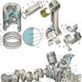
Mechanical unit injectors
The unit injector consists of fuel pump high pressure and spray head in one housing. The injection pump is in the upper part, the sprayer is in the lower part. The unit injector is usually located under valve cover and it is not visible from the outside. The peculiarity of the location is due to the fact that the pump is driven by additional cams provided on. The principle of operation of a conventional mechanical unit injector is quite simple. The cam of the camshaft through the rocker arm pushes the plunger of the unit injector. The pressure in it rises sharply and upon reaching a certain value raises the nozzle needle and fuel enters the combustion chamber. , and the expanding gases push the piston.
 Electronic unit injectors
Modern electronic unit injectors work a little differently. Pressure is created in the same way as in a mechanical one - with the help of a plunger, but the electronic engine control unit manages the injection moment. The number of supplied portions of fuel can be up to ten per cycle in three main phases. The first is a preliminary injection, when a small portion of fuel is supplied to the cylinder, to preheat the combustion chamber and better ignite the next, second, main portion. The third phase is intended for afterburning unburned fuel and heating (regeneration).The minimum cost of a unit injector for VW Passat 2006 is 18 thousand rubles
To ensure accurate metering of each portion of fuel and to provide several injections in one stroke, a solenoid valve is used that controls the raising of the atomizer needle.
Advantages and disadvantages of pump nozzles
The unit injectors, in contrast to the accumulator injection, allow the injection of fuel at a pressure of more than 2000 bar. This allows the fuel to be atomized more efficiently and therefore burns more completely. Therefore, engines with unit injectors are characterized by high power density, economy and environmental friendliness. In addition, engines with such an injection system are quieter than their counterparts with Common Rail or mechanical injection pump with. In addition, the injection system with unit injectors is much more compact, although the disadvantages of this system are no less serious. The most important is the extreme exactingness of the pump injectors to the quality of the fuel. Water, dirt and surrogate fuel are lethal for them. The second serious drawback is the high cost of the unit injector. Repairing this precision assembly is difficult outside the factory. Therefore, car owners with such a power system have to purchase new unit injectors.Operation and maintenance of unit injectors
The most common unit injector malfunctions are associated with wear on the valve assembly and nozzles. The reason for the failure of these nodes is primarily associated with misuse vehicle with this system.To prolong the life of the unit injectors, it is necessary to observe several simple rules... Firstly, you need to refuel only at proven gas stations.At the end of the 90s, engines with unit injectors occupied 20% of the fuel equipment market of European diesels
Secondly, under no circumstances add petrol, kerosene, brake fluid and other "KAMAZ" tricks for bringing summer diesel fuel to frost resistance of winter. Thirdly, it is necessary to shorten the interval for replacing fuel filters. Moreover, you can install, permitted by the manufacturer. Because analogs often do not provide required level filtration.