The term "sensor" came into use when, in the distant 20-40s, measuring probes (sensors) found everyday use (for example, they began to be used in automobile and household appliances).
Sensors - synonymous concepts are (measuring) probes and (measuring) sensitive elements - they convert physical or chemical (mostly non-electrical) quantities into an electrical quantity E; this often occurs through other non-electrical intermediate transformations.
As electrical quantities, not only current and voltage are used, but also the amplitudes of current and voltage, frequency, period, phase or duration of an electrical oscillation pulse, as well as electrical quantities - resistance, capacitance and inductance. The sensor can be characterized using the following equations: (1) E \u003d / (Ф, URU2 ...) Output signal of the sensor (2) Ф \u003d g (E, YpY2 ...) The desired indicator. If the functions f or g are known, then they represent a sensor model, with the help of which the required indicator is calculated from the values \u200b\u200bof the output signal E and the influence parameters Y in an almost unmistakably mathematical way ("smart" sensors, English: intelligent or smart sensors).
In practice, the sensor model has some free parameters that can be used to calibrate the model to the actual characteristics of an individual sensor instance. With a digital sensor signal, model calibration parameters are most often stored in a programmable, non-volatile memory device (PROM). In contrast to the usual analog compensation of influencing quantities, here it is possible to successfully correct not only linear influences, but also intense nonlinear processes. It is also a big advantage that with this method of calibration, which is carried out solely by electrical connection, each sensor can be calibrated during its operation.
 In a rather generalized formulation, the term "smart sensors" (Smartsensor) can be defined as follows, smart, in some cases built-in sensors, or sensors with individual Special electronics, which are simply called sensors at the place of use, allow maximum use of the hidden in the sensor (statistical and dynamic ) accuracy by means of microelectronics, which is their difference from conventional sensors. In this case, the information received by the sensor, especially the complex information of structures consisting of several sensors, can be compressed by additional processing, that is, it can be displayed at a higher level (than a simple sensor allows), without the need to use a large number external devices... There is no clear rule as to whether signal processing devices should be integrated in sensors, however, it is recommended that no distinction be made, for example, between elementary sensor, sensor element and built-in sensor.
The programming or calibration of a "smart" sensor is carried out - as well as the adjustment of conventional analog sensors - often with the help of an external computer (Host) in three stages.
The mainframe systematically varies both the xe and the influence parameter (s) and adjusts a number of relevant and representative operating points in the process. At the same time, the "smart" sensor displays uncorrected "clean signals". By means of significantly more accurate reference sensors, the central computer simultaneously receives the "true" values \u200b\u200bof xe and y. Based on the comparison of both values, the central computer calculates the necessary correction parameter and interpolates it over the entire measurement range.
Based on the previously obtained data, the central computer calculates model parameters typical for a given instance, for example, for linear display of graphical characteristics, and stores them in the PROM of the “smart” sensor. During control processing, this data can first be emulated in the RAM of the host computer, before it is finally "built into the memory" of the smart sensor. If the graphical characteristics are brought in line with polynomials of a higher degree, then, in order to avoid protracted calculation processes, three-dimensional graphical characteristics (Look-up tables) are also saved in the "smart" sensor. It is well proven to maintain large cell performance combined with simple linear interpolation between anchor points.
Working phase
Now the "smart" sensor is disconnected from the central computer, and it can make calculations using the stored model data of the measured value xe practically without errors. It transmits it to a connected control unit, for example in digital form, binary serial code or in analog form (for example, using pulse modulation). The measured value can be transmitted digitally via the bus interface to the following control units. This correction process can be repeated if erasable PROM is used. This is already an advantage during the sensor development phase. Example: Two-dimensional graphical surface of the reference points s (Tn, 0m) of a "smart sensor" for measuring the distance S: For high-precision machining of a sensor that acts as a variable inductance, its natural graphical characteristic and its temperature regime approximated to polynomials of the 5th degree. It is an element that outputs the frequency of a completely simple oscillator circuit as an uncorrected output signal of period T. As a sensor model for the segment s, instead of 36 polynomial coefficients and long polynomial processing, only the total graphic surface is taken into account (written to the file), including 32 x 64 \u003d 2048 characteristic parameters sn, m (in PROM) and a simple interpolation algorithm (in ROM). If the signal T appears between the reference points Tp and Tn + 3 / and the temperature O between the reference points © m und © m + i, then, as shown in the figure, interpolation is carried out two-dimensionally between the "error-free" stored standard parameters S ..... S and the desired parameter s (T, О) is determined as the result of interpolation.
 Use in a car
With the increasing demands on all vehicle functions, over the past 40 years, sequential, initially mechanically implemented regulation and control functions have been replaced by electronic units (ECUs, electronically controlled units). This has resulted in a high demand for sensors and final control elements with which these electronic control units, on the one hand, could measure the condition vehicle, and on the other hand could influence them. The automotive industry has become the engine behind the development and production of a wide variety of sensors over the years. If in the beginning they were mainly electromechanical or had a macro-mechanical shape, then the trend of the late eighties began to develop unambiguously towards miniature sensors manufactured using semiconductor methods (Batch Processing).
Temporarily insignificant role in thick-film technology was played by sensors, which originated from hybrid technologies. They are still sometimes found today, for example, in plate oxygen probes and high temperature sensors for measuring in the exhaust zone. If temperature and magnetic field sensors were first designed as switch-like structures and manufactured in separate batches, this trend was strengthened when it was possible to structure silicon different ways, as well as micromechanically in two and three dimensions (coordinate axes), and using a very effective methods firmly and functionally to connect in various positions.
Since electronic semiconductor switching technologies are based almost exclusively on silicon as the main working material, all other materials and technologies play a minor role in all sensors. For example, quartz can also be micromechanically formed using an anisotropic etching technology, but unlike silicon, it has better piezoelectric properties. III-V semi conductors, such as gallium arsenide (GaAs), have a much wider operating temperature range than silicon, which could offer significant advantages when used at various locations in a vehicle. Thin mechanical layers are very well suited for making precision tensile resistors, precise temperature sensors and magnetic field dependent resistors. With the help of silicon, it was possible to integrate electronics into the sensor in a monolithic way. This technology, despite a few exceptions (eg Hall-IC), has lost its significance due to the large number and variety of processing steps and the resulting inflexibility. Hybrid technologies for integration into a very narrow space by all the rules require much more economical, functional and equivalent solutions.
Whereas sensor development was initially focused almost exclusively on in-vehicle transmission, chassis and bodywork systems, as well as road safety, the direction latest developments more and more focused on the outer near and far surroundings of the vehicle: ultrasonic sensors detect obstacles during parking and in the foreseeable future will allow (in combination with other sensors) to automatically park the car; short-range radar detects objects in the area around the vehicle that are likely to become the cause of the accidentto gain time and set up pre-collision safety systems (Precrash sensors); image sensors can detect not only road signs, but also transfer them to the driver's display, as well as recognize the contours of the road, warn the driver about the danger of deviating from the road and, if necessary, allow driving for a long time. automatic mode; in combination with infrared rays and a screen in the driver's field of vision, IR-sensitive image sensors allow monitoring the road at night and even in fog (night vision); Long-range radar sensors monitor the road at a distance of 150 m in front of the vehicle, allowing it to adapt to the speed of the vehicles in front, as well as to keep the movement in automatic mode for a long time.
Sensors and final control elements form interfaces (matching devices) as the periphery between the vehicle with its complex drive, braking, travel and body functions, as well as driving and navigation functions and the digital electronic control unit as a data processing device. As a rule, the matching switch provides sensor signals for the control unit in the required standardized form (measuring chain, measuring system). These matching switching devices, coordinated with special sensors, are available in large numbers in an integrated form. They represent an essential and valuable addition to the sensors presented here, without which the use of sensors would be impossible, and the quality of measurements can only be assessed in combination with them.
In the multi-step process “vehicle” shown, the sensor data of other operating elements (controls), as well as the driver using a simple control switch, can also be influenced. Indicators inform the driver about the status and progress of the entire process.
Sensor market data
The share of added value of electrics and electronics in the car is currently about 26%. Meanwhile, almost every second sensor is built into a car with an annual growth rate, which is still defined by double digits. Since the late nineties, an increasing share has been made by micromechanical and microsystem sensors, in 2005 they accounted for already a third of the total volume.
Unlike the general sensor market, the sector for passenger cars Europe with a market share of 41% and Bosch as the world's leading manufacturer are now well ahead of America with only 34%. Overall, the automotive sensor market has grown from US $ 8.88 billion in 2005 to US $ 11.35 billion in 2010. by 28%.
There are three typical groups of firms that make sensors for vehicles. Semiconductor industry: This is where sensors from semiconductor manufacturing came into being through the use of some special work steps. They serve the entire sensor market, including the automotive industry, and have a well-functioning sales system. Micromechanical sensor manufacturing processes are constantly being improved in conjunction with semiconductor processes. However, these companies do not have specific know-how in the field of exclusively automotive destination, control and installation technologies.
Specialized, often medium-sized sensor manufacturers who do not manufacture semiconductor switching devices, but have chosen only a few types of sensors as a narrow focus in order to supply them to the entire market or even to specific areas such as, for example, the automotive market.
Major suppliers for automotive industry and system manufacturers (eg Bosch) or large subsidiaries car manufacturerswhich specialize in the needs and supplies of their subsidiaries. Enterprises in this segment have also been manufacturing semiconductor and hybrid switching circuits since the introduction of electronics into the car, in close cooperation with semiconductor manufacturers (process development, licensing). A large number of inventions (know-how) have been developed here in the field of vehicle equipment, control and installation technologies, based on system knowledge.
Send your good work in the knowledge base is simple. Use the form below
Students, graduate students, young scientists using the knowledge base in their studies and work will be very grateful to you.
Posted on http://www.allbest.ru
MINISTRY OF EDUCATION AND SCIENCE OF UKRAINE
NATIONAL TECHNICAL UNIVERSITY
"KHARKIV POLYTECHNICAL INSTITUTE"
Department of Materials Science
Test
Electrical Materials Science
On the topic: "Sensors used in modern car»
2nd year student
TMZ-11 groups
Linnik Artem Alekseevich
harkov town
INTRODUCTION
І. DEFINITION OF THE SENSOR
II. SENSOR CLASSIFICATION
ІІІ. SENSORS IN MODERN CARS
1. New developments of sensors
2. Parktronic sensors
3. Sensors in car burglar alarms
LIST OF USED LITERATURE
INTRODUCTION
In recent years, in the technology of measuring and regulating the parameters of various processes, the role of the industry of manufacturing and using sensors has been increasing more and more. This industry, constantly evolving, serves as the basis for the creation of various options for automatic control systems.
This development is primarily due to the giant progress in microelectronics. The wide range of microcomputer applications in home appliances, automotive and other industrial sectors increasingly requires low-cost, large-scale sensors. As a result, new interesting and at the same time inexpensive sensor devices appear.
Continuous improvement of cars is the most important factor in the development of the economy of our country. A modern car consists of a large number of mechanical components that are quite perfect. Therefore, in recent years, there has been a tendency towards the complication and development of electrical and electronic equipment in cars, the cost of which in modern trucks often exceeds 30% of the total cost.
One of the most important problems of a modern motor transport enterprise is fast and high-quality troubleshooting of cars. When operating a car, hidden malfunctions may appear that do not externally manifest themselves, but, being unnoticed, they can lead to serious breakdowns, and, consequently, to expensive repairs.
In addition, preventive diagnostics allows the company to save significant funds by identifying faults and eliminating them in a timely manner, which reduces downtime in repairs, and, therefore, reduces labor costs and repair costs.
The emergence of semiconductor devices, integrated circuits, miniature micro-computers makes it possible to quickly and efficiently detect emerging malfunctions and eliminate them both during the operation of the vehicle and during its preparation for operation.
To diagnose certain parameters of a car, first of all, reliable, high-precision sensors are needed.
І. DEFINITION OF THE SENSOR
The control process consists in receiving information about the state of the control object, monitoring it and processing it by the central device and issuing control signals to the executive devices. Sensors of non-electrical quantities are used to receive information. Thus, temperature, mechanical movement, presence or absence of objects, pressure, flow rates of liquids and gases, rotation speed, etc. are controlled. sensor car parking sensors alarm
The sensor can be simultaneously affected by various physical quantities (pressure, temperature, humidity, vibration, nuclear reaction, magnetic and electric fields, etc.), but it must perceive only one quantity, called the natural quantity.
Sensors inform about the state of the external environment by interacting with it and converting the reaction to this interaction into electrical signals. There are many phenomena and effects, types of transformation of properties and energy, which can be used to create sensors.
Sensor, sensor (from the English. Sensor) - the concept of control systems, primary converter, element of the measuring, signaling, regulating or control device of the system, converting the controlled value into a signal convenient for use.
There are several definitions of a sensor. The following definitions are widely used:
1.sensitive element that converts the parameters of the medium into a suitable technical use a signal, usually electrical, although possibly of a different nature (for example, a pneumatic signal);
2. a finished product based on the above element, including, depending on the need, devices for signal amplification, linearization, calibration, analog-to-digital conversion and an interface for integration into control systems. In this case, the sensing element of the sensor itself may be called a sensor.
3.sensor is a part of the measuring or control system, which is a constructive set of measuring transducers, including a converter of the type of signal energy, located in the area of \u200b\u200baction of the influencing factors of the object and receiving naturally encoded information from this object.
4. sensor - a structurally separate part of the measuring system, containing one or more primary converters, as well as one or more intermediate converters.
These definitions are consistent with the practice of using the term by sensor manufacturers. In the first case, the sensor is a small, usually monolithic electronic device, for example, a thermistor, photodiode, etc., which is used to create more complex electronic devices... In the second case, it is a device, complete in its functionality, connected via one of the known interfaces to the system. automatic control or registration. For example, photodiodes in matrices, etc. In the third and fourth definitions, the emphasis is on the fact that the sensor is a structurally separate part of the measuring system that perceives information, and therefore has self-sufficiency for this task and certain metrological characteristics.
Currently, various sensors are widely used in the construction of automated control systems.
Sensors are an element technical systemsdesigned to measure, signal, regulate, control devices or processes. Sensors convert the controlled value (pressure, temperature, flow rate, concentration, frequency, speed, displacement, voltage, electric current, etc.) into a signal (electrical, optical, pneumatic), convenient for measurement, transmission, conversion, storage and registration information about the state of the measurement object.
Historically and logically, sensors are associated with measurement technology and measuring instruments, for example, thermometers, flow meters, barometers, an artificial horizon device, etc. The generalizing term sensor has strengthened in connection with the development of automatic control systems, as an element of the generalized logical concept sensor - control device - executive device - control object. As a separate category of sensor use in automatic systems registration of parameters can be distinguished by their application in systems of scientific research and experiments.
Recently, due to the reduction in the cost of electronic systems, sensors with complex signal processing, parameter setting and regulation capabilities and a standard control system interface are increasingly used. There is a definite tendency of an expansive interpretation and transfer of this term to measuring instruments that appeared much earlier than the massive use of sensors, and also, by analogy, to objects of a different nature, for example, biological ones. The concept of a sensor in terms of practical orientation and details of technical implementation is close to the concepts of a measuring instrument and measuring device, but the readings of these instruments are mainly human readable, and the sensors are usually used in automatic mode.
II. SENSOR CLASSIFICATION
When classifying sensors, the principle of their operation is often used as a basis, which, in turn, can be based on physical or chemical phenomena and properties.
Classification by type of output quantities:
· Active (generator);
· Passive (parametric).
Measured variable classification:
Pressure Sensors:
· Absolute pressure;
· Excessive pressure;
· Rarefaction;
· Pressure-rarefaction;
· Pressure difference;
· Hydrostatic pressure.
Flow sensors:
· Mechanical flow meters;
· Differentiators;
· Ultrasonic flow meters;
· Electromagnetic flowmeters;
· Coriolis flow meters;
· Vortex flowmeters.
· Float;
· Capacitive;
· Radar;
· Ultrasonic.
Temperatures:
· Thermocouple;
· Resistance thermometer;
· Pyrometer;
· Concentration sensor;
· Conductivity meters.
Radioactivity (also referred to as radioactivity or radiation detectors):
· Ionization chamber;
· Direct charge sensor.
Movements:
· Absolute encoder;
· Relative encoder;
Positions:
· Contact;
· Contactless.
Photo sensors:
· Photodiode;
· Photosensor.
Angular position sensor;
Angle-code converter;
Vibration sensor;
Piezoelectric sensor;
Eddy current sensor;
Mechanical value sensor;
Rotor expansion sensor;
Absolute expansion sensor;
Arc protection sensor.
Functional classification:
· Optical sensors (photo sensors);
· Magnetoelectric sensor (Based on the Hall effect);
· Piezoelectric sensor;
· Tenzo converter;
· Capacitive sensor;
· Potentiometric sensor;
· Inductive sensor.
Classification by the nature of the output signal:
· Discrete;
· Analog;
· Digital;
· Impulse.
Medium classification:
· Wired;
· Wireless.
Classification by the number of input quantities:
· One-dimensional;
· Multidimensional.
Manufacturing technology classification:
· Elemental;
· Integral.
Let's consider the main types:
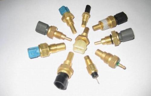
Temperature sensors. Among other sensors, temperature sensors are distinguished by a particularly wide variety of types and are one of the most common.
Figure: 1. The design of the temperature sensor.
The mercury column glass thermometer has been known for a long time and is widely used today. Thermistors (Fig. 1), the resistance of which changes under the influence of temperature, are used quite often in various devices due to the relatively low cost of sensors of this type... There are three types of thermistors: with a negative characteristic (their resistance decreases with increasing temperature), with a positive characteristic (with increasing temperature, the resistance increases) and with a critical characteristic (the resistance increases at a threshold temperature value). Usually, the resistance changes quite sharply under the influence of temperature. To expand the linear section of this change, resistors are connected in parallel and in series with the thermistor.
Thermocouples are especially widely used in the measurement field. They use the Seebeck effect: an EMF arises in a junction of dissimilar metals, approximately proportional to the temperature difference between the junction itself and its terminals. The range of temperatures measured by the thermocouple depends on the metals used. Temperature-sensitive ferrites and capacitors use the effect of temperature, respectively, on the magnetic and dielectric constant, starting from a certain value called the Curie temperature and for a particular sensor depends on the materials used in it.
Thermal diodes and thyristors are semiconductor sensors that use the temperature dependence of the conductivity of a pn junction (usually on a silicon crystal). Lately practical use found the so-called integrated temperature sensors, which are a thermosensitive diode on one chip with peripheral circuits, for example, an amplifier, etc.
Optical sensors. Like temperature sensors, optical sensors are very diverse and widely used. According to the principle of optical-electrical conversion, these sensors can be divided into four types: based on the effects of photoelectron emission, photoconductivity, photovoltaic and pyroelectric.
Photovoltaic emission, or external photoelectric effect, is the emission of electrons when light falls on a physical body. For electrons to escape from the physical body, they need to overcome the energy barrier. Since the energy of photoelectrons is proportional to hc / l (where h is Planck's constant, c is the speed of light, l is the wavelength of light), the shorter the wavelength of the irradiating light, the greater the energy of the electrons and the easier it is for them to overcome this barrier.
The effect of photoconductivity, or internal photoelectric effect, is a change in the electrical resistance of a physical body when it is irradiated with light. Among the materials with the effect of photoconductivity, there are ZnS, CdS, GaAs, Ge, PbS, etc. The maximum spectral sensitivity of CdS occurs approximately at light with a wavelength of 500-550 nm, which corresponds approximately to the middle of the sensitivity zone of human vision. Optical sensors operating on the effect of photoconductivity are recommended for use in exposure meters of photographic and film cameras, in automatic switches and dimmers, flame detectors, etc. The disadvantage of these sensors is a slow response (50 ms and more).
The photovoltaic effect consists in the emergence of an EMF at the p-n-junction terminals in a semiconductor irradiated with light. Under the influence of light, free electrons and holes appear inside the p-n-junction and an EMF is generated. Typical sensors that work on this principle are photodiodes, phototransistors. The same principle of operation has the optoelectric part of two-dimensional solid-state image sensors, for example, sensors on devices with a charge-coupled device (CCD sensors). The most commonly used substrate material for photovoltaic sensors is silicon. The relatively high response speed and high sensitivity in the range from the near infrared (IR) zone to visible light provide these sensors with a wide range of applications.
Pyroelectric effects are phenomena in which electric charges appear on the surface of a physical body due to changes in the surface temperature "relief", corresponding to these changes. Among the materials with similar properties are many other so-called pyroelectric materials. A field-effect transistor is built into the sensor housing, which allows converting the high impedance of the pyrotechnic element with its optimal electrical charges into a lower and optimal output resistance of the sensor. Of this type of sensors, infrared sensors are the most commonly used.
There are few optical sensors that have sufficient sensitivity over the entire light range. Most sensors have optimum sensitivity in a fairly narrow ultraviolet, or visible, or infrared region of the spectrum.
Main advantages over other types of sensors:
1. Possibility of non-contact detection.
2. Possibility (with appropriate optics) of measuring objects with both extremely large and extremely small sizes.
3. High speed response.
4. Convenience of using integral technology (optical sensors, as a rule, solid-state and semiconductor), providing small dimensions and long service life.
5. Extensive scope of use: measurement of various physical quantities, shape determination, object recognition, etc.
Along with the advantages, optical sensors also have some disadvantages, namely, they are sensitive to pollution, they are subject to the influence of extraneous light, background light, and also temperature (with a semiconductor base).
Pressure Sensors. There is always a great need for pressure transmitters and they find very wide applications. The principle of recording pressure serves as the basis for many other types of sensors, for example, sensors for mass, position, liquid level and flow rate, etc. In the overwhelming majority of cases, pressure indication is carried out due to deformation of elastic bodies, for example, a diaphragm, Proudhon tube, corrugated membrane. Such sensors have sufficient strength, low cost, but it is difficult to receive electrical signals in them. Potentialometric (rheostatic), capacitive, induction, magnetostrictive, ultrasonic pressure sensors have an electrical signal at the output, but are relatively difficult to manufacture.
Today, strain gauges are increasingly used as pressure sensors. Semiconductor strain gauges of the diffusion type seem to be especially promising. Diffusion strain gauges on a silicon substrate have high sensitivity, small size, and are easily integrated with peripheral circuits. A circular diaphragm is formed on the surface of an n-conductive silicon crystal by etching using thin-film technology. At the edges of the diaphragm, film resistors with p-conductivity are applied by diffusion. If pressure is applied to the diaphragm, the resistance of some resistors increases, while others decrease. The sensor output signal is generated by a bridge circuit that includes these resistors.
Diffusion-type semiconductor pressure sensors like the one described above are widely used in automotive electronics, in all kinds of compressors. The main problems are temperature dependence, environmental instability and service life.
Moisture sensors and gas analyzers. Humidity is a physical parameter that, like temperature, a person has been faced with since ancient times; however, reliable sensors have not been available for a long period. Most often, human or horse hair was used for such sensors, which lengthens or shortens with changes in humidity. At present, a polymer film coated with lithium chloride swelling from moisture is used to determine moisture content. However, sensors on this basis have hysteresis, instability of characteristics over time and a narrow measurement range. More modern sensors are those that use ceramics and solid electrolytes. They have eliminated the above disadvantages. One area of \u200b\u200bapplication for humidity sensors is a variety of atmosphere controllers.
Gas sensors are widely used in manufacturing enterprises for the detection of all sorts of harmful gases, and in households for the detection of flammable gas leaks. In many cases, it is required to detect certain types of gas and it is desirable to have gas sensors that are selective in relation to the gaseous environment. However, the response to other gas components makes it difficult to create selective gas sensors with high sensitivity and reliability. Gas sensors can be made on the basis of MOS transistors, galvanic cells, solid electrolytes using the phenomena of catalysis, interference, absorption of infrared rays, etc. Semiconductor ceramics, in particular, or devices operating on the principle of catalytic combustion, are mainly used to detect the leakage of domestic gas, for example, liquefied natural gas or combustible gas such as propane.
When using gas and humidity sensors to register the state of various media, including aggressive ones, there is often a problem of durability.
Magnetic sensors. Main feature magnetic sensors, as well as optical, is speed and the ability to detect and measure in a non-contact way. But unlike optical sensors, this type of sensor is not sensitive to pollution. However, due to the nature of the magnetic phenomena, the effective operation of these sensors largely depends on such a parameter as distance, and usually magnetic sensors require sufficient proximity to the acting magnetic field.
Hall sensors are well known among magnetic sensors. Currently, they are used as discrete elements, but the use of Hall elements in the form of ICs made on a silicon substrate is rapidly expanding. Such ICs are the best suited to modern sensor requirements.
Magnetoresistive semiconductor elements have a long history of development. Now the research and development of magnetoresistive sensors, which use ferromagnets, are revived again. The disadvantage of these sensors is the narrow dynamic range of detectable changes in the magnetic field. However, high sensitivity, as well as the possibility of creating multi-element sensors in the form of ICs by sputtering, i.e., the manufacturability of their production, constitute undoubted advantages.
ІІІ. SENSORS IN COWBELTCARS
1. New sensor developments
New battery sensor from Bosch. The Bosch concern has developed electronic sensor vehicle battery status (EBS). The built-in measuring electronics of the sensor determines the main physical parameters of the battery - voltage, current and temperature, and software algorithms calculate values \u200b\u200bthat accurately describe its condition. In addition, the sensor makes a situational prediction of the state of charge.
In modern vehicles, this information is used by the energy management control unit, which makes it possible to always maintain a sufficient battery level to properly start the engine, even after long periods of inactivity. The data used to control the alternator and engine can help reduce fuel consumption and therefore exhaust emissions and increase battery life. Battery monitoring plays an important role in hybrid vehicles with start-stop function.
The sensor consists of a chip with electronic filling and a resistive element for measuring current. Together with the pole terminal, they form mounting blockwhich connects directly to the battery and fits in a recess next to the terminal on standard car batteries... The novelty wins over other solutions in this area due to significant savings in free space and money.
In addition to the hardware base of the sensor, Bosch, in cooperation with Varta, has developed software to determine the state of the battery, the algorithms of which are fully integrated into the EBS chip. The sensor directly measures the temperature, voltage and current of the battery and from this data calculates its capacity and state of charge, as well as current and future performance. The information is transmitted via the LIN interface to the higher-level vehicle energy control unit, which allows the battery state of charge to be optimized.
Bosch starts production of the world's first modules throttle made of composite materials for gasoline engines... The new product weighs 25% less and is more economical to manufacture than traditional metal modules. Other advantages of the novelty include: more precise adjustment of the opening angle, simplified adaptation to different engines and car models, as well as improving safety in the event of an accident: parts made of composites are broken into small components under the influence of a sudden impact.
In system electronic control With the throttle position, the throttle module is the main element in regulating the engine air consumption and thus the engine power output. Based on the information on the position of the gas pedal, the engine control unit calculates the required opening angle of the throttle valve, the ignition timing and the amount of fuel injected. The signal from the throttle position sensor monitors the actual position of the throttle valve and ensures that the target position is adhered to. In addition, there is no need to include the throttle valve module in the coolant circuit, since the low thermal conductivity of the synthetic material significantly reduces the risk of icing.
The housing and damper of the new generation of DV-E8 modules are made of durable, strong glass fiber reinforced with thermoplastic, which has a high temperature and wear resistance. The design allows easy adaptation to different models engines and vehicles.
Motorola has developed a new generation of automotive tire pressure sensors and new series inertial sensors.
Pressure control devices have an original design and are mounted in a standard wheel valve. They are self-powered from the supplied batteries and can be easily installed on any vehicle.
In addition to the sensors, this system includes an on-board receiver that receives signals from the sensors and converts them into data that the driver can understand.
They promised to establish industrial production of these devices by 2008.
In addition to pressure sensors, Motorola announced the serial production of inertial motion control systems. They monitor the change in the dynamics of the car depending on the manipulation of the driver and are able to prevent skidding and overturning of the car.
Motorola inertial sensors are designed to be supplied to assembly plants as part of the original eSP systems development of this company. Motorola is hoping for industrial orders for new products from auto makers and intends to adapt them to promising 2006 models.
2. Parktronic sensors
Parking Radar, also known as Acoustic Parking System (APS), Parktronic or Ultrasonic Parking Sensor, is an auxiliary parking system installed on some vehicles; This is a system that facilitates the procedure for parking a car, reversing it in the dark and maneuvering in bottlenecks... It minimizes the risk of damage to the car body from an approaching obstacle, as it warns the driver in a timely manner about the decreasing distance to the object. Some models of parking sensors themselves prevent a possible collision with an approaching object.
Parktronic measures the distance to an approaching object using ultrasound. The system uses ultrasonic sensors (Fig. 2, 3) embedded in the front and rear bumpers to measure the distance to nearby objects. The system emits an intermittent warning sound (and, in some versions, displays distance information on a display built into the dashboard, in the rearview mirror, or mounted separately) to indicate how far the vehicle is from an obstacle.
Figure: 2. Ultrasonic sensor type MA40MF14-18.
Displays and parking sensors are highly accurate and show the driver not only the direction of the approaching obstacle, but also the distance to it if it is less than one and a half meters. At this time, with decreasing distance, sound signal sounds more often, and when the distance becomes less than 25 cm, the parking sensors sound signal becomes continuous.
The parking sensors (sensors themselves) that come with the kit come in a variety of sizes and colors. They are mounted in the car bumper. Many car models have standard places for installing parking sensors, or holes are cut for their installation. Appearance the car does not deteriorate in this case.
Many brands of cars are currently being produced with pre-installed parking sensors (parking sensors), which confirms the need for this system.
Figure: 3. Ultrasonic sensor type MA40S5.
There are many varieties parking systems, differing mainly in the number and location of ultrasonic transducers.
The simplest systems use two sensors mounted on the rear bumper of the car. The system is activated when the driver engages the gear reverse... The number of sensors depends on the design of the parking sensors. Their number can range from two to eight. The accuracy of the parking sensors depends on the number of sensors.
Sensors can be built-in or overhead. For mortise sensors, special holes are drilled in the body of the bumper, and then, having prepared the places, the sensors are installed. This is the most common installation method. And you don't need to drill anything to install the patch sensors. The sensors are simply attached with a special adhesive to the car bumper.
In Russia, the AvtoVAZ plant installs parking radar for Lada Priora cars in Lux configuration. Almost any car that does not have a parking radar as standard can be installed as an additional option.
3. Sensors in car burglar alarms
By design car alarms are divided into two types: compact and modular.
The alarm system in a compact design is a monoblock containing almost all the elements of the system: electronic components, siren, sensors. Due to the fact that the electronic components are located in the siren case, which is installed under the hood, they are more accessible to intruders.
Signaling in modular design consists of separate parts: central unit, siren and external sensors. The central unit is located in the passenger compartment, protected from access, and is not exposed to atmospheric influences. This type of alarm is also equipped with additional sensors and actuators (central lock, trunk lock, power windows, etc.). Has a wider range of service functions.
Almost all alarms use service systems, such as monitoring and checking for false positives:
· Auto Testing - automatically checks all alarm sensors, detects any malfunctions, saving the user from their long and expensive search;
· Bypass of faults (Auto Bypass) with automatic monitoring. The system automatically (at the request of the user) disables faulty sensors or circuits, maintaining the overall performance of the alarm and the protection of the vehicle.
Automotive burglar alarms use a variety of sensors from the simplest (contact) to complex, which are practically independent intelligent electronic devices (volumetric sensors).
Contact sensorsgenerally all alarms are used. These sensors are designed to protect car doors, hood and trunk. Pushbutton switches are usually used as such sensors (as a rule, standard door switches).
Broken glass sensor reacts to the characteristic sound of broken glass. This is a mic-slime sensor and can be single-stage or double-stage. The response of such a sensor largely depends on the type of glass, its thickness and the location of the microphone. A single-level sensor reacts only to the characteristic sound of breaking glass. Two-level - registers the sound of a blow on glass and the actual ringing of broken glass. To trigger and send a corresponding signal to the central unit, such a sensor must register two types of signals with an interval of no more than 150 ms.
The principle of operation of these sensors is to respond to vibrations with a frequency of about 1500 Hz, produced by broken glass, or to vibrations high frequencycaused by the internal stresses of the glass when it is cracked or cut.
Electromechanical sensor enclosed in a sealed ampoule. Its contacts are made in the form of two electric filaments semi-submerged in mercury. Oscillations generated when glass breaks cause momentary electrical contact openings.
Acoustic sensor designed to catch vibrations with a frequency of about 1500 Hz, which appear when glass partitions are destroyed. The signal received by the microphone is amplified and analyzed electronic circuitconnected to the sensor.
Piezoelectric sensor - this is a more accurate detector, since it has high selectivity. It does not react to the low frequencies that occur when the glass is hit if it is not broken, but it picks up vibrations of about 200 kHz, caused by the internal stresses of the broken glass. Thus, untimely alarms are excluded, which occur, for example, when passing a heavy or high-speed car near a glass partition or when aircraft drone penetrates a wall.
Shock sensor (vibration) is usually supplied in the basic set of car alarms. It is a device that records vibration and shock to the vehicle body. If the vibration amplitude exceeds the set value, an alarm is triggered.
The sensor works on the basis of the piezoelectric effect or electromagnetic induction, when a permanent magnet moves along the coil winding and thereby creates in it alternating current... Such a sensor is called an electromagnetic, magnetic resonance or Piezosensor sensor.
A rare variant of the vibration sensor device - vibration sensor with balls. At rest, the electrical contact is closed. One or both balls freely lie on two contacts, which can be structurally made in the form of two metal railings. At the moment of impact, the balls bounce off the contact, causing short interruptions, which are analyzed by the electronic circuit, through which the sensitivity to impact is adjusted.
The sensitivity is determined by the duration of the contact opening when the balls bounce off each other.
Tilt sensor is a very simple sensor. It is very popular with domestic car owners. The tilt sensor consists of two magnets and a coil. One magnet is fixed motionlessly at the base of the coil, and the second is suspended in the magnetic field of the first. When the sensor body is tilted, the second magnet is displaced relative to the first, which leads to a change in the magnetic field in which the coil is located. An EMF is induced in the coil winding, which is amplified and is an information signal of the sensor. In foreign car alarms, such tilt sensors are rarely used, but they are widely used in motorcycle security systems.
Voltage drop sensor monitors voltage in security mode on-board network car. In the event of power surges caused, for example, by opening the car doors, the sensor sends a corresponding signal to the alarm control unit. This type of sensor is built into the central unit and is included in the basic set of most alarms.
Current sensor works in the same way as a voltage drop sensor. However, in the armed mode, it registers a current surge that occurs when connecting additional load to a power source (for example, when opening a car door). The current sensor must have a very high sensitivity to small inrush currents and therefore is rarely used in alarms.
Using power failure sensor in car alarms is considered traditional. If the alarm power supply circuit is open (disconnecting the terminals battery) the sensor is triggered and turns on the self-powered siren, if it is connected to the alarm.
Motion Sensor often referred to as the Proximity Sensor because it is triggered when a heat-emitting object, such as a person, enters the sensor's protection area. The Proximity Sensor usually has one sensing zone (90-110 °) and is resistant to false alarms. The disadvantage of the simplest and cheapest sensors is that they are triggered at a certain rate of change in heat flow. For example, if the sun warms up the interior of a car, the sensor may be triggered.
More advanced sensors do not have this drawback. Their reliability and resistance to thermal interference is ensured by multi-channel heads and sophisticated electronic signal processing in the sensor itself. In simple models, signal processing is carried out using analog methods, and in more complex models, digital ones, for example, using an integrated processor.
Volumetric sensors are among the most sensitive security systems in the car interior. They register any movement in the closed space of the passenger compartment. Therefore, many alarms provide for a remote sensor shutdown mode using a key fob. Volumetric sensors include:
1. The ultrasonic sensor (Ultrasonic) is designed to detect movements in the vehicle interior. Its action is based on the interference of ultrasonic vibrations. The sensor includes an ultrasonic frequency emitter and a receiver, which are spaced apart in the passenger compartment. When closed windows and doors, the space monitored by the sensor is limited by the vehicle interior, and a stable interference pattern is formed at the point where the receiver is located. When any volume and interior penetrate, the stability of the interference pattern is disturbed and an alarm is generated. The main disadvantage of the ultrasonic sensor is false alarms when convection air flows in the vehicle heating system.
2. The microwave sensor is designed to detect movement inside and around the vehicle. Therefore, it is also called a two-zone sensor. The first security zone was outside the car, and the second was the salon itself. The principle of operation of the sensor is based on the registration of changes in the interference pattern of radio waves in the centimeter range (transparent for car windows), formed by the transmitter. The device is very effective, but requires careful adjustment of the sensitivity, as the security zone extends outside the vehicle, which can cause false alarms of the sensor.
Often, dual-zone sensors are used to scare off persons approaching the vehicle. When the first zone is triggered, the headlights are turned on and a weak sound signal is heard. In the most advanced models, a speech synthesizer is used, which invites passers-by who come too close to the car to move away.
3. Infrared sensor (Infrasonic) as well as ultrasonic protects only the car interior. Its action is based on registration of changes in the interference pattern of the infrared field. This sensor is capable of monitoring large enclosed spaces, therefore it is recommended for installation in the salons of minibuses, vans, etc. The main drawback is the large current consumption compared to other volumetric sensors.
4. The volume change sensor is designed to register changes in the air pressure in the car interior, which occurs, for example, when the door or glass of the car is opened. This sensor has a very high sensitivity and in this regard, its false alarms are possible, especially when the car interior cools down in winter period... It is rarely used in car alarms.
CONCLUSIONS
Sensors of non-electrical quantities are used to receive information. Thus, temperature, mechanical movement, presence or absence of objects, pressure, flow rates of liquids and gases, rotation speed, etc. are controlled. The sensor can be simultaneously influenced by various physical quantities (pressure, temperature, humidity, vibration, nuclear reaction, magnetic and electric fields, etc.), but it must perceive only one quantity, called the natural quantity.
Sensors inform about the state of the external environment by interacting with it and converting the reaction to this interaction into electrical signals.
Currently, various sensors are widely used in the construction of automated control systems. Sensors are an element of technical systems designed to measure, signal, control, control devices or processes.
Recently, in connection with the reduction in the cost of electronic systems, sensors with complex signal processing, the ability to configure and regulate parameters and a standard interface of the control system are increasingly used.
Modern cars are equipped with a huge number of sensors that monitor temperature, pressure, flow rates of liquids and gases, rotation speed, the presence or absence of objects around the car during parking, and are also used for security systems cars. All this makes it possible to speed up the process of detecting breakdowns, and, accordingly, car repairs, and also makes it easier for the driver to handle the car.
LIST OF USED LITERATURE
1) Yutt V.E. Electrical and electronic equipment of cars - M. Transport 1983.
2) Kako N., Yamane J. Sensors and micro-computers. L: Energoatom from dates, 1986.
3) W. Titze, K. Schenck. Semiconductor circuitry. M: Mir, 1982.
4) P. Horowitz, W. Hill. The art of circuitry, vol. 2, M: Mir, 1984.
5) Reference book of the radio amateur designer. M: Radio and communication, 1990.
6) G. Wigleb, Sensors: Design and Application, 1989.
7) Osipovich L.A., Sensors of physical quantities, 1979.
8) Modern sensors. Directory. J. FRAYDEN Translated from English by Y. Zabolotnaya, edited by E. L. Svintsov. M: Technosphere-2005
9) Sensors. Perspective directions of development. Aleinikov A.F., Gridchin V.A., Tsapenko M.P. Publishing house of NSTU - 2001
10) Sensors in modern measurements. A.F.Kotyuk Moscow. Radio and communication - 2006
11) Pinsky F.I., Davtyan R.I., Chernyak B.Ya. Microprocessor control systems car engines internal combustion: Textbook. allowance. - M .: Publishing house "Legion-Avtokada", 2002
12) VAZ cars: Technology of body repair and body parts / Ed. B.V. Prokhorov. - L .: Mechanical engineering, 1987
Posted on Allbest.ru
Similar documents
a brief description of control signal sensors and emergency modes... Alarm sensors emergency pressure oil in the car. Contact, contact-transistor, contactless (electronic), microprocessor systems spark ignition.
term paper added 02/11/2013
Mass air flow sensors, throttle position. Purpose of the coolant temperature sensor. Fuel pressure control. Adsorber purge valves, gasoline pump. Method for checking the phase and position sensors of the crankshaft.
term paper, added 12/17/2009
Engine management system. Fuel system: general concept, device. The principle of operation of the injection and exhaust system of gasoline engines. The main purpose of the sensors. Electronic ignition system: general view, design, features of work.
presentation added on 12/08/2014
New trends and promising technologies automotive sensors for speed and position, oxygen concentration, mass air flow, pressure, temperature, oil level and condition, detonation in Powertrain systems. Sensors for gas engines.
thesis, added 05/20/2009
Electronics and electrical equipment of transport, transport and technological machines. Electronic information systems sensors. Magnetoelectric indicators on cars. Alarm pressure indicator sensor. Difference of pressure sensors from each other.
abstract, added 06/07/2011
Fuel pressure sensor operation. Fuel pressure deviation from the set value. Actuation of the control valve in the fuel rail. Tire pressure sensor. The main element of the direct pressure control system. The main types of oil pressure sensors.
presentation added on 11/29/2016
Electronic engine control system of a VAZ Priora car, its components and principles of their operation. Sensors and ignition system. Engine power supply device and wiring diagram. Checking and troubleshooting. Safety precautions when working with ECM.
lecture added 06/16/2014
Characteristic anti-lock braking system, designed to maintain the stability of the vehicle when braking. Operation of the control unit, modulator, wheel speed sensors. Analysis of the trajectory stabilization system Electronic Stability Program.
test, added 06/11/2012
The key system of the unmanned vehicle of the robot and ITS is an integrated system that is an on-board computer. Sensors on-board computer... Integrated navigation system and the tasks that it solves. Global Positioning System.
abstract, added 05/20/2009
Classification existing systems control of a traction electric drive of a car and a description of their work, schemes of these units and their main elements. Description of the sensors that make up the system. Diagnostics of the traction electric drive of a hybrid vehicle.
Good day, dear readers, in this article we will analyze many reasons but mostly symptoms of malfunction of vehicle sensors.Remember that before you go to a hundred and panic, you should spend a little time and try to find the cause of the malfunction yourself and save money.
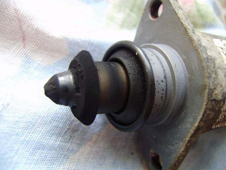
Signs of a malfunction of the TPS sensor:
- idling possible high revs, this is the most characteristic feature;
- a noticeable decrease in engine power and deterioration in throttle response;
- when you press the accelerator jerks, dips and twitching;
- floating idle speed;
- when shifting gears, the engine turns off spontaneously;
- overheating is possible;
- detonation.
(personally, my symptoms were high revs, the inability to brake with the engine, jerks, a decrease in power and, accordingly increased consumption gasoline).
The photo shows heavily worn tracks
The reasons for the malfunction of the TPS sensor may be:
- oxidation of contacts - you can help in this case, you need to take special liquid WD and a cotton swab to clean all contacts in the block and under the lid;
- worn-out sensor substrates if a resistive layer deposition was provided for in their design;
- the movable contact fails - some tip of this contact may break, then a scuff is formed and other tips also fail;
- the throttle valve does not close completely at idle - in this case, you can file it off a little seats sensor and the flap should close.
Idle valve malfunction symptoms:
- unstable engine idle speed;
- spontaneous increase or decrease in engine speed;
- stopping the engine when turning off the transmission;
- no increased speed when starting a cold engine;
- decrease in speed idle move engine when the load is turned on (headlights, stove, etc.).
 The idle valve in this state will not be able to function normally.
 The check error does not always pop up.
The best prevention of the idle valve is to periodically remove and clean the idle valve, usually in the fall and spring.
Signs of malfunction of the DMRV sensor:
Signs of a malfunction of the dmrv or absolute inlet pressure sensor are characterized by:
- Up to 70 degrees, the machine works more or less well, after 70, an unstable idle speed begins;
- Dips during acceleration and undertraining;
- The car sometimes stalls at idle when hard pressing gas pedals;
- Increased consumption;
- Unpleasant exhaust smell;
- Pops in the muffler during operation and sometimes pops during intake manifold... (incorrect ignition timing due to faulty sensor)
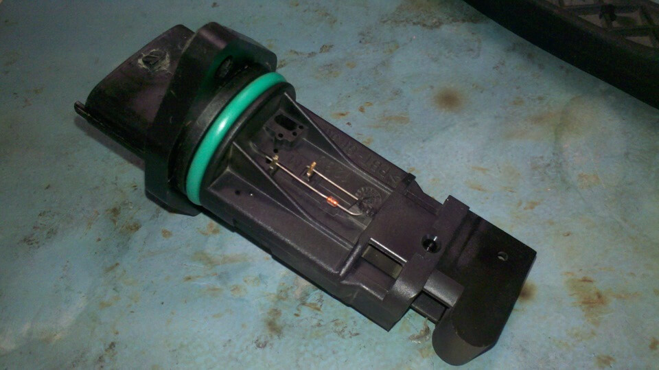 The air flow sensor is very sensitive and it is not recommended to clean it yourself, the more often you change the filter, the longer it will serve you.
 The check error pops up only when the dmrv sensor has stopped working completely, and it can give incorrect readings for a long time.
You can check the dmrv or the mass air flow sensor with a multimeter or a diagnostic scanner at hand.
Signs of a malfunctioning speed sensor:
- the speedometer does not work or gives incorrect readings;
- unstable idle;
- increased fuel consumption;
- the motor stops developing full power.
- the arrow of the fuel gauge reacts almost instantly to fluctuations in the fuel level in the tank, because the computer thinks that the car is not moving, and less “smooths” the sensor readings;
- odometer does not wind mileage;
sensor in automatic transmission
- when switching the speed, the automatic transmission is reset itself to neutral, or it switches spontaneously illogically;
- the car stops responding to the gas pedal and starts coasting;
- in city traffic when gaining speed, the gearbox sharply increases the revs and does not accelerate, does not react to other modes 2 and 1. It seems to go only at 1 speed but does not brake the engine.

The principle of operation of the speed sensor on all cars is the same and it is quite possible to restore it yourself, let's take an example.
Signs and causes of a malfunctioning knock sensor:
- Comes into a disrepair quite rarely. Than the sensor breaks, more likely something will happen to its wiring. Perhaps something happened to them if, at speeds exceeding 3000, the engine's sensitivity to how high-quality fuel is poured into it increases. If the fuel is of poor quality, there will be a “knock of fingers”.
- symptoms of incorrect installation of the ignition timing. Who drove cars with mechanical system engine management, he knows what I'm talking about. One has only to shift the UOZ by a few degrees to the early or late side, so the engine will either lose dynamics, as if you are driving on the handbrake, or it will start to detonate - ringing at an insignificant load or "shooting through" exhaust system... Everything depends on the detonation resistance of the poured fuel and the UOZ at which your engine is running.
For example (from experience), I met Audi with V-shaped engine with two knock sensors, which flatly refused to develop full power. The engine was gaining momentum very sluggishly, and Pavlodar specialists pointed to a clogged fuel system. However, when checked on the bench, the nozzles sprayed the fuel perfectly, and the pressure gauge showed the reference value of the pressure in the rail. But still, when measuring with a stroboscope UOZ, it turned out that it was displaced by more than 10 degrees from the normal value, which is described in the manual. The reason for this was one of the two knock sensors on the second engine block.
Another interesting case related to a malfunction of the knock sensor was with subaru engine... At the time of purchase, a car, like the Audi described above, did not develop full power. At the same time, the engine ran very smoothly, fuel system (nozzles, gas tank) was absolutely clean and there were no signs of any malfunctions at all. However, the owner of the car complained that he could not overtake the usual injection top ten. From experience with Audi, we tested the knock sensor on this engine, but the sensor turned out to be very “alive”. Resistances 540 kOhm, as expected from the specification. DD reacted vividly to tapping - 30-40 mVolts.
The reason was not found soon. On several American sites, I found owners of exactly the same cars who also complained about the terrible dynamics of the engine. But smart Americans quickly realized what was going on and shunted the knock sensor circuit with a capacitor, and there were those who didn't want to mess with electronics and preferred a lining made of a piece of rubber that was placed under the sensor. As a result, the sensitivity of the DD decreased and the appearance of small vibrations in the motor was completely ignored. Thus, after a few kilometers, the car became frisky and dynamic.
The check error does not always pop up.
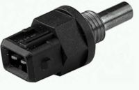
Signs of a malfunction of the coolant temperature sensor:
- The electronic control system sets the engine temperature suitable for starting to zero degrees Celsius and the corresponding command is sent to the auxiliary air regulator. In the event of a malfunction of the temperature sensor, the proportions of air and gasoline in the mixture will be far from optimal, which will make it difficult to start the engine in low temperatures. After the engine can still be started, after two minutes, the electronic unit the control will decide that the coolant temperature has risen to 80 degrees. For this reason, you will have to play the gas pedal not only when starting, but also when the engine warms up.
There will be problems with the same malfunction in hot weather. When the engine heats up to a temperature close to the maximum allowable temperature, the control unit will assume that the antifreeze temperature is normal and will not take measures to correct the ignition timing. Power loss will occur and engine detonation will occur.
- idle speed is below normal.
- incorrect operation of the car fans, turn on on cold engine and do not turn on when required, as a result of which the temperature rises.
- the appearance of dark smoke from the exhaust pipe.
Most cars have 2 coolant temperature sensors, data from the first goes to the dashboard, and the on and off of the radiator fan depends on the data of the second sensor.
The error does not always pop up.
Camshaft position sensor malfunction symptoms:
- the gearbox is locked in one gear, usually in the first, restarting the engine can solve the problem;
- the car moves in jerks;
- the vehicle experiences a difficult acceleration after 60 km / h.
- the engine stalls periodically, especially often on idle;
- possible pops in the system exhaust gases;
- the spark disappears, the engine will not start.
Crankshaft position sensor malfunction symptoms:
- detonation appears during intensive acceleration;
- unstable idle speed;
- vehicle speed rises or falls on its own;
- the engine cannot be started.
Signs of a malfunctioning ignition coil:
- It breaks down quite often. Symptoms include power sags that occur, a decrease in overall engine power, instability at idle, dips during acceleration, and even two-cylinder shutdown. If the distance to the service station is several kilometers, and it is possible to reach it, then turn off the corresponding nozzles. Otherwise, the gasoline injected by the injectors into the non-working cylinders, and the oil will be washed off from the disabled cylinders, after which it will flow into the crankcase.
You can check by turning off the ignition coils in turn and when you come across a faulty coil, the engine will not change.
Symptoms of a generator malfunction:
- When the engine is running, the indicator lamp for battery discharge flashes (or is continuously on);
- Discharge or recharge (boil-off) of the storage battery;
- Low light car headlights, rattling or quiet beep when the engine is running;
- A significant change in the brightness of the headlights with an increase in the number of revolutions. This can be permissible when increasing the speed (overglowing) from the idle mode, but the headlights, having lit up brightly, should not further increase their brightness, remaining at the same intensity;
- Extraneous sounds (howl, squeak) emanating from the generator.
Rapid advances in electronics and electrical engineering over the past years and decades have resulted in a dramatic increase in the number of electronic components in a car. Along with hydraulics and pneumatics, electronics have penetrated all parts of the car. Individual electronic components and complex electronic systems are becoming more compact, cheaper and, at the same time, more efficient. The result is new possibilities for the use of electronics in the car, allowing the range of existing functions to be continuously expanded. Such progress inevitably affects the organization of the work of the stations. maintenance in automotive... The amount of routine work is dwindling and the skills needed to do it are diminishing. It is becoming increasingly important to obtain the necessary information through electronic means, to understand the operation of complex systems and, ultimately, to carry out correct diagnostics based on targeted control and measurement work. In this regard, another transformation must occur: the transition from thinking and understanding of individual systems to complex thinking and understanding of systemic relationships. Naturally, from now on, as before, knowledge and understanding of the principle of operation and details of individual systems will retain their significance. At the same time, however, it is still necessary to know and understand the connections and connections with the rest of the systems.
The electronic control systems of a modern car are unthinkable without sensors. Automotive sensors evaluate non-electrical values \u200b\u200band convert them into electrical signals. The signal is voltage, current, frequency, etc. The signals are converted into digital code and are transferred to the electronic control unit, which, in accordance with the programmed program, activates the actuators.
Sensors are active and passive. In an active sensor, an electrical signal is generated by an internal energy conversion. A passive sensor converts external electrical energy.
Sensors are used in almost all vehicle systems. In the engine, they measure the temperature and pressure of air, fuel, oil, coolant. Many moving parts of the vehicle (crankshaft, camshaft, throttle valve, shafts in the gearbox, wheels, EGR valve) position and speed sensors are connected. A large number of sensors are used in active safety systems.
Depending on the purpose, the following types of automotive sensors are distinguished: position and speed, air flow, control of exhaust gas emissions, temperature, pressure.
Position and speed sensors
Conversion of the linear or angular displacement of the controlled object into an electrical signal is performed using position and speed sensors. The car uses sensors for crankshaft position, camshaft position, throttle position, fuel level, accelerator pedal position, wheel speed, steering wheel angle.
Position and speed sensors are made by contact or non-contact. Although proximity sensors are preferred, contact devices are still widely used. With all the advantages, contact sensors have one significant drawback - a tendency to contamination and, accordingly, a decrease in measurement accuracy.
Contact position sensors include potentiometers with moving contactsthat measure the linear and angular movements of an object. Moving contacts move along the length of the variable resistor and change its resistance proportional to the actual movement of the object. Potentiometers are widely used as throttle position sensor, gas pedal position sensor, volumetric air flow meter, fuel level sensor, etc.
The operation of contactless position and speed sensors is based on various physical phenomena and effects, and their corresponding sensors: inductive, Wiegand, Hall, magnetoresistive, optical and many others.
Inductive sensor widely used as a crankshaft position sensor. They contain a permanent magnet, a magnetic circuit and a coil. When a steel object (a gear tooth) approaches the sensor, the magnetic field increases and an alternating voltage is induced in the coil. Unlike inductive sensors, Wiegand sensors do not use a permanent magnet, but are activated by an external magnet.

Most demanded proximity sensors built on hall effect... The essence of the effect is that a permanent magnet connected to the measured object, when rotating, generates a voltage proportional to the angular position of the object. Hall sensors use several circuits for measuring position and speed: a rotary chopper, a multi-pole ring magnet, a ferromagnetic gear rotor. For measuring angular velocity of the gear rotor, a differential Hall sensor is used - two adjacent measuring elements that allow you to see the tooth and cavity at the same time.
Magnetoresistive sensors began to be used relatively recently, but are very popular. They are built on the magnetoresistive effect - the property of some current-carrying materials to change their resistance in an external magnetic field. Distinguish between anisotropic magnetoresistors (AMR) and giant magnetoresistors (GMR). AMR sensors use the electrical resistance of ferromagnetic materials. The measuring element of the HMR sensor consists of alternating ferromagnetic and non-magnetic layers. Anisotropic magnetoresistors are used in the steering wheel angle sensor.
IN optical sensor to determine the angular position, a light-modulating disk with alternating transparent and opaque sectors is used. The disc is located between the LED and the photoresistor. When moving (turning) the disk, electrical impulses are generated on the photoresistor, which determine the angle and speed of the shaft rotation.
Air flow sensors
The air flow to the engine is determined by volume or mass. Sensors that determine the volume flow rate are called volumetric flow meters... The operation of such sensors is based on the assessment of the damper movement proportional to the amount of air flow.

Mass air flow is estimated by a mass air flow sensor. The most widely used are micromechanical flow meters built on thin-film heated elements - thermistors. The air passing through the thermistors cools them. Moreover, the more air passes through, the more the thermistors are cooled. The determination of mass air flow is based on the measurement of power and current required to maintain constant temperature thermistors.
Exhaust gas emission sensors
Content regulation harmful substances in the exhaust gases are provided by emission control sensors, which include an oxygen concentration sensor and a nitrogen oxide sensor.

(also called a lambda probe) is installed in the exhaust system and, depending on the oxygen content in the exhaust gases, generates a certain signal. Based on the signal, the engine management system maintains a stoichiometric air-fuel ratio (so-called lambda control).
On modern vehicles equipped with catalytic converter, two oxygen concentration sensors are installed. The oxygen sensor at the outlet of the catalytic converter monitors its performance and ensures the content of harmful substances in the exhaust gases within the established norms.
Nitrogen oxide sensor controls the content of nitrogen oxides in the exhaust gases. It is installed in the exhaust system of gasoline engines with direct injection fuel after an additional (accumulative) converter. The sensor includes two cameras. In the first chamber, the oxygen concentration is estimated. In the second chamber, nitrogen oxides are reduced to oxygen and nitrogen. The concentration of nitrogen oxides is estimated by the amount of reduced oxygen.
Temperature sensors
The temperature is measured in different systems car:
| Cooling system | Coolant temperatures |
| Engine management system | Intake manifold temperatures |
| Climate control system |
Outside air temperatures; Air temperature in the car |
| Lubrication system | Oil temperatures |
| Automatic transmission | Temperatures working fluid |
To measure temperature, use nTC Thermistors... With increasing temperature, the resistance of the thermistor decreases, and the current increases accordingly. A thermocouple is also used as a temperature sensor - a conductor consisting of two different metals and generating thermoelectric voltage under the influence of temperature.
Pressure Sensors
Modern cars use a large number of pressure sensors that measure the pressure in the intake manifold, fuel pressure in the injection system, tire pressure, pressure of the working fluid in braking systems, oil pressure in the lubrication system.

To estimate the pressure, piezoresistive effect, which consists in changing the resistance of the strain gage during mechanical stretching of the diaphragm. The measured pressure can be absolute or relative. The intake manifold pressure sensor measures absolute pressure, i.e. air pressure relative to vacuum.
The presented classification does not cover all car sensors... A number of other sensors should be mentioned: knock sensor, oil level sensor, rain sensor. The knock sensor evaluates engine vibration that accompanies uncontrolled ignition of the air / fuel mixture. The sensor is a piezoelectric element that generates an electrical signal when vibrated.
The oil level sensor in a modern engine replaces the function of the dipstick. The oil level can be measured with a float switch or a more advanced thermal sensor, which, in addition to the oil level, measures its temperature. The rain sensor provides automatic operation wipers. Structurally, it is combined with a light sensor.
Mass air flow sensor (DMRV.
The purpose of the sensor. Operating principle.
The mass air flow sensor is designed to convert the air flow entering the engine into a DC voltage.
The sensor information allows you to determine the engine operating mode and calculate the cyclic filling of the cylinders with air at steady-state engine operating conditions, the duration of which exceeds 0.1 second.
The sensitive element of the sensor is built on the principle of a thermoresistive anemometer and is made in the form of a platinum heated thread. The thread heats up electric shock, and with the help of a temperature sensor and a sensor control circuit, its temperature is measured and maintained constant.
Only if the air flow through the sensor increases, then the platinum filament begins to cool, the sensor control circuit increases the filament heating current until its temperature is restored to its original level, thus the amount of filament heating current is proportional to the air flow rate.
The secondary transducer of the sensor converts the heating current of the filament into a DC output voltage.
Over time, the filament becomes dirty, which leads to a shift in the calibration characteristic of the sensor.
To clean the filament from dirt after turning off the engine (if certain conditions are met), the filament is burned through to 900-1000 \\ xB0C by a current pulse for 1 second. The control unit generates a burn control impulse.

Ketones and esters cannot be used for flushing. For three reasons:
1. dissolve the compound.
2. When dry, they cool the crystal very strongly. He can "Burst / Crack".
3. Dissolve the "Mask" on the crystal (this is rel. Not scary, but in the center of the crystal there is a polymer film in the window, it looks like polyethylene terephthalate, on which there is also a mask and metal. Spraying) if the mask is washed off, the film will deform and tear off.
Do not:
- Climb there with matches / toothpicks, etc.;.
- Flush with all kinds of corrosives such as Winns and Carbocline.
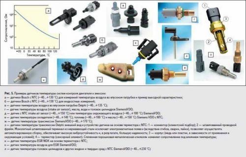
In general, what remains?
WD - 40. There are diesel fuel and heavy fatty acids. They wash well, but leave a film for a long time. It needs to be washed off. It is necessary to wash off with alcohols (ethyl / methyl / isopropyl) mixed with distilled water (20% water), or ethyl / butyl / propyl - acetates (CH.D.a. they mix normally with water (but household goods are dirty, and leave plaque I think it is better to pour the crystal from a syringe with a thin needle, and dry it with a "Native" fan, turning it on from a computer. Well, at least it will not die artificially, and no one is immune from natural death. Nice results by flushing the mass air flow sensor gives the usual flushing isopropyl alcohol with a preheated, with the help of a technical hair dryer, up to 60-70 degrees DFID and flushing liquid.
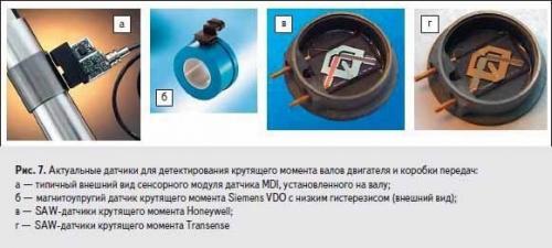
Throttle position sensor (TPS).

The throttle position sensor is mounted on the side of the throttle block on the same axis with the throttle actuator. The throttle position sensor reads the readings from the throttle pedal position. The main enemy of the throttle position sensor is engine washers.
The life of a throttle position sensor is completely unpredictable. Violations in the operation of the throttle position sensor are manifested in increased idle speed, in jerks and dips at low loads.

Knock sensor.

The knock sensor is installed on the engine block between the 2nd and 3rd cylinders. There are two types of knock sensor - resonant (barrel) and broadband (tablet. Knock sensor different types not interchangeable.
The knock sensor is reliable, but requires regular cleaning of the connector. The principle of operation of the knock sensor is the same as that of a piezo lighter. The harder the blow, the more stress.
Tracks engine knocking knocks. In accordance with the signal from the knock sensor, the controller sets the ignition timing. There is a detonation - a later ignition. Failure or breakage of the knock sensor manifests itself in the "Dullness" of the engine and increased fuel consumption.
It is a hollow hexagonal body with a threaded projection for screwing into an internal combustion engine. Inside the case, a double-layer piezoelectric element is screwed with an ordinary screw, which generates an emf when it is exposed to sound frequency vibrations through the sensor case.
These vibrations are converted into an audio signal using a piezoelectric element. Thus, with the help of DD, the EFI block "Hears" what is happening in the engine during its operation. That is, it is a kind of microphone, or rather, a piezoceramic pickup (like on a turntable.
The body is filled on the edge with a special compound that feels like fragile crumbling artificial rubber. This compound (on the forum it is called "Resin") not only protects the piezoelectric element from exposure environment, but also creates a specific frequency response (amplitude - frequency response) of the signal, since the DD spectrum should lie in the range of 1400-6000 Hz with a central frequency in the region of 2700 Hz (approximate detonation frequency.
In the event that detonation processes appear, then the EFI unit automatically changes the ignition timing (uos) until the detonation processes are minimized or completely eliminated.
Thus, DD is an integral part of the chains for correcting the formation and the most efficient combustion of the fuel mixture. Failure of the diesel engine is accompanied by the appearance of a self-diagnosis error, detailed processes in the internal combustion engine (with the characteristic so-called "ringing of fingers"), worse traction, increased fuel consumption.
Oil pressure sensor.
The oil pressure in the system is monitored by a special sensor installed in the oil line. The electrical signal from the sensor goes to control lamp on dashboard... Cars can also be fitted with an oil pressure gauge.
The oil pressure sensor can be incorporated into the engine management system, which shuts down the engine if the oil pressure drops dangerously.
On modern engines the oil level control sensor and the corresponding signal lamp on the dashboard. Along with this, an oil temperature sensor can be installed.
Coolant temperature sensor (doe).
The coolant temperature sensor is installed between the block head and the thermostat. The coolant temperature sensor has two contacts. The main functional purpose of the coolant temperature sensor is what colder motor, the richer fuel mixture.
Structurally, the coolant temperature sensor is a thermistor (resistor), the resistance of which changes depending on temperature. Typical values \u200b\u200b100 gr. - 177 ohm, 25 gr. - 2796 ohm, 0 gr. - 9420 ohm, - 20 gr. - 28680 ohms. The coolant temperature affects almost all engine control characteristics. The coolant temperature sensor is very reliable.
The main faults are a violation of the electrical contact inside the sensor, insulation failure or wire breakage.
Failure of the coolant temperature sensor - turning on the fan on a cold engine, difficulty starting a hot engine, increased fuel consumption.
Oxygen sensor.
The oxygen sensor (lambda probe) is installed on the exhaust pipe of the muffler. A serious but highly reliable electrochemical device.
The task of the oxygen sensor is to determine the presence of oxygen residues in the exhaust gases.
There is oxygen - a lean fuel mixture, no oxygen - a rich one.
The oxygen sensor readings are used to adjust fuel delivery.
The use of leaded gasoline is strictly prohibited.
Failure of the oxygen sensor leads to an increase in fuel consumption and harmful emissions.
Crankshaft position sensor (DPKV).
The crankshaft position sensor is designed to generate an electrical signal when the angular position of a special toothed disk mounted on the engine crankshaft changes.
The crankshaft position sensor is installed near the crankshaft pulley and reads the risk signals. This is the main sensor, according to the readings of which the cylinder, the fuel supply time and the spark are determined.
Structurally, the crankshaft position sensor is a piece of magnet with a coil of thin wire. Very hardy.
The crankshaft position sensor works in tandem with toothed pulley crankshaft. Sensor failure - engine shutdown. IN best case limiting engine speed in the region of 3500 - 5000 rpm.
Phase sensor (DKV camshaft).
Fits only on 16-valve engine. Information for organizing fuel injection into a specific cylinder is used.
Failure of the sensor puts the fuel supply in a pairwise - parallel mode, which leads to a sharp enrichment of the fuel mixture.
The phase sensor is installed on the engine at the top of the cylinder head behind the intake camshaft pulley.
The timing disc with a slot is located on the intake camshaft pulley. The passage of the slot through the range of the phase sensor corresponds to the opening intake valve the first cylinder.
Idle speed regulator (IAC), camshaft DKV.
It is a device that is necessary in the system to stabilize the engine idle speed. IAC is a stepping motor with a spring-loaded tapered needle.
While the engine is idling, due to a change in the flow area of \u200b\u200bthe additional air supply channel bypassing the closed throttle valve, the amount of air necessary for its stable operation enters the engine.
This air is taken into account by the mass air flow sensor (MAF) and, in accordance with its amount, the controller supplies fuel to the engine through the fuel injectors.
According to the crankshaft position sensor (DPKV), the controller monitors the number of engine revolutions and, in accordance with the engine operating mode, controls the IAC, thus adding or reducing air supply bypassing the closed throttle valve (see Photo - 2 and Photo - 3.
With the engine warmed up to operating temperature, the controller maintains idle speed. In the event that the engine is not warmed up, the controller, due to the IAC, increases the speed and, thus, warms up the engine at an increased crankshaft speed. This operating mode of the engine allows you to start driving the car immediately and without warming up the engine.
The idle speed control is mounted on the throttle body and is attached to it with two screws.
Unfortunately, on some cars, the heads of these mounting screws can be bored out or the screws are set on varnish, which can make it much more difficult to dismantle the IAC to replace it or clean the air channel. In such cases, it is rarely possible to do without dismantling the entire throttle body.
IAC is an executive device and its self-diagnosis is not provided in the system. Therefore, in case of malfunctions of the idle speed controller, the "Check Engine" lamp does not light up. Symptoms iAC faults are in many ways similar to faults of the TPS (throttle position sensor), but in the second case, the "Check Engine" lamp clearly indicates a TPS malfunction.
The following symptoms can be attributed to malfunctions of the idle speed controller:
- Unstable engine idle speed, - spontaneous increase or decrease in engine speed, - engine shutdown when the gear is disengaged, - no increased speed when starting a cold engine, - reduced engine idle speed when the load is turned on (headlights, stove, etc.) .. to dismantle the idle speed regulator, with the ignition off, disconnect its four-pin connector and unscrew the two fastening screws. Install the IAC in reverse order. In addition, the O-ring on the flange must be lubricated engine oil... Author unknown.